Terry's tale. (S3 resto ++)
Discussion


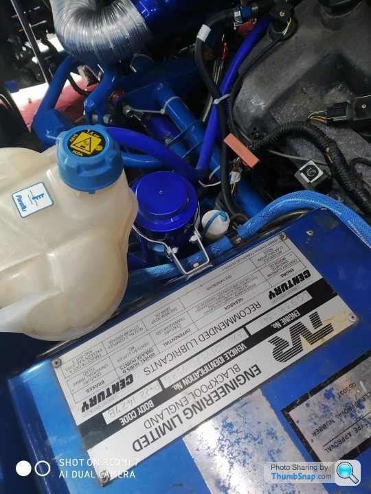
 Must be a great feeling when all the hard work that you've put in comes to the moment you turn the key and it starts.
As I suspected, the continuous running issue was a back feed. The ign switched +12v to the ECU just doesn't like being in the same ignition supplied circuit as the +12v as sent to the warning lights, especially the alternator charging ignition warning light. Some of which I had changed to Led, so you could say it was my own fault.
Anyway it's all fixed now. The engine both starts and stops on the key.
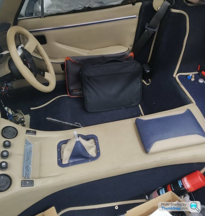
Lots of ECU map tuning to do. But I'm leaving that until later. As next I want to tidy up all of the new wiring looms (engine bay & behind the dash), then start on getting the interior back in situ. Including getting the door electrical features to work as they should (I'm adding remote central locking).
So that's my car aerobic exercise done for today
I hope this weather holds as it's great to work outside for a change. But it also means I've got some slabs to lay
T.
Anyway it's all fixed now. The engine both starts and stops on the key.
Lots of ECU map tuning to do. But I'm leaving that until later. As next I want to tidy up all of the new wiring looms (engine bay & behind the dash), then start on getting the interior back in situ. Including getting the door electrical features to work as they should (I'm adding remote central locking).
So that's my car aerobic exercise done for today
I hope this weather holds as it's great to work outside for a change. But it also means I've got some slabs to lay
T.
Hi guys....
A little help required please.
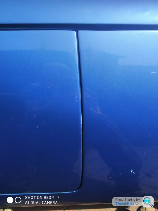
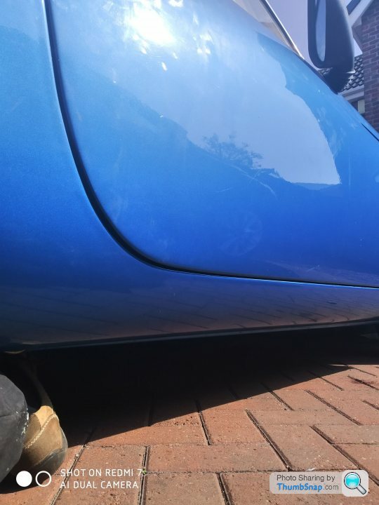
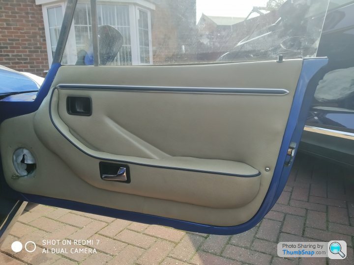
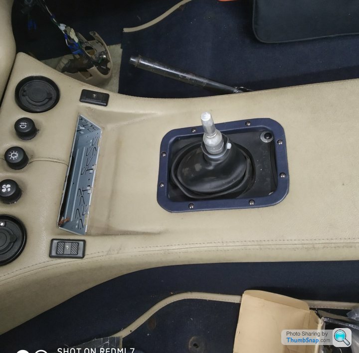
I'm ready to close up the driver's door, refit the card etc. All the electrical things work, as does the door locking mechanism.
My question is regarding the fit of the door. I have read, and understand how the hinges fit, work, and adjust.
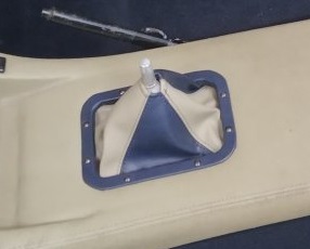
See my attached photos, all of the door gaps are good and equal, and there is only a tiny bit of lift on the hinges. But the door appears to low at the top/back, about 10mm lower than the rear side panel (where the velcro normally is).
Is yours the same as mine, or is it level away ?
T.
A little help required please.
I'm ready to close up the driver's door, refit the card etc. All the electrical things work, as does the door locking mechanism.
My question is regarding the fit of the door. I have read, and understand how the hinges fit, work, and adjust.
See my attached photos, all of the door gaps are good and equal, and there is only a tiny bit of lift on the hinges. But the door appears to low at the top/back, about 10mm lower than the rear side panel (where the velcro normally is).
Is yours the same as mine, or is it level away ?
T.
 ...…. I'll have a look to separate the ign live to the Emerald tomorrow.
magpies said:
does seem that way, runs on for about 3 or 4 seconds and the ecu LED stays green - next time it happens I'll try pressing the throttle to see if the revs rise before stopping.
Possible the switched ignition line is being backfed from the alternator energiser circuit due to too low resistance in the 'no charge' warning light combined with very low load on the switched ignition circuit? I expect you'll find the brake lights are powered through the switched ignition too, so if a foot on the brakes while you switch off prevents the problem it would support this hypothesis.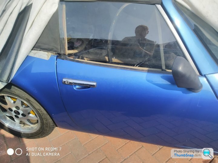
And a little bit of help required please...
My grey handbook has this 'S' logo on it...
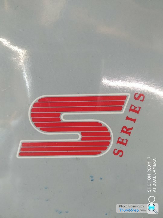
I have also seen images of S's with a coach line and that S logo...
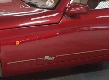
Not being an expert on the S history, I have to guess that maybe the coach line and logo were a customer option.
My early S3 does not have it, but I would like to include it once my resto is completed.
The image above is S3C.
Question... Does anybody have a good image of the S3 logo, so that I can get a printshop to make me a couple... That's unless you know of supplier ?
TIA.
T.
My grey handbook has this 'S' logo on it...
I have also seen images of S's with a coach line and that S logo...
Not being an expert on the S history, I have to guess that maybe the coach line and logo were a customer option.
My early S3 does not have it, but I would like to include it once my resto is completed.
The image above is S3C.
Question... Does anybody have a good image of the S3 logo, so that I can get a printshop to make me a couple... That's unless you know of supplier ?
TIA.
T.
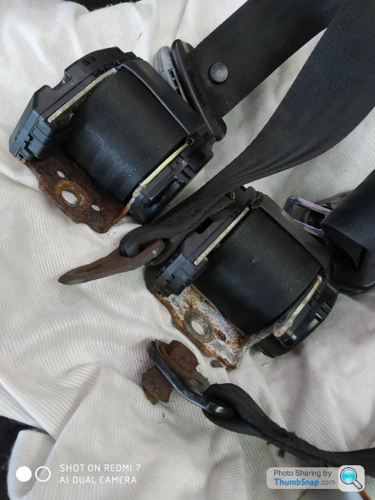
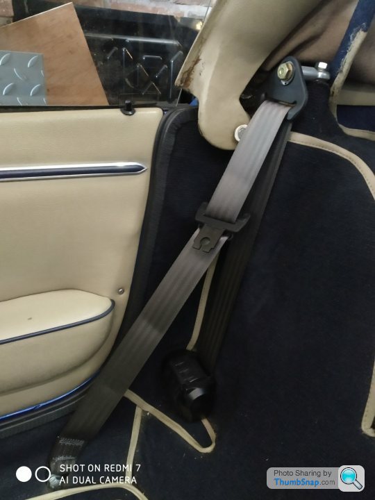
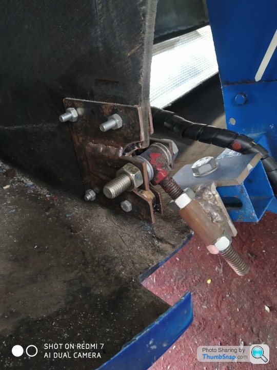
Regards the bolt holes, I'm a boat man as well as a car man so when I fitted up my body (and a nice shiny new pair of VW Transporter seat belts) I used Marine Silicone. This is the same stuff I use to make screw holes for fittings on my boats watertight.
It eventually shrinks a little (after half a dozen years of flexing) so I make an annual inspection to check it isn't failing, then just remove and refit with more sealant if necessary.
It eventually shrinks a little (after half a dozen years of flexing) so I make an annual inspection to check it isn't failing, then just remove and refit with more sealant if necessary.

So, after odd jobbing around the car outside while the weather was good, once it took a turn for the worse, it was time the S returned to the garage. And do an outstanding serious job....
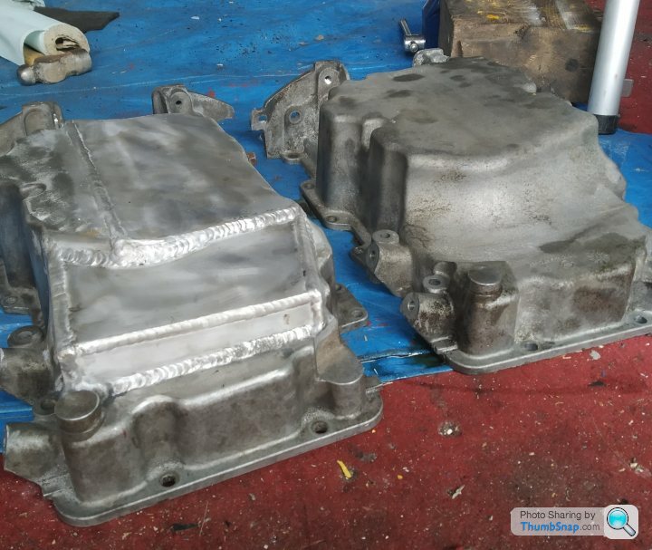
Anyone who knows the Jag AJ30 V6 engine, will know that in rwd format it has a strange growth on the front of the sump, I assume it's just to increase capacity, therefore increasing service intervals. It has a deep section too, not a good thing on the S !
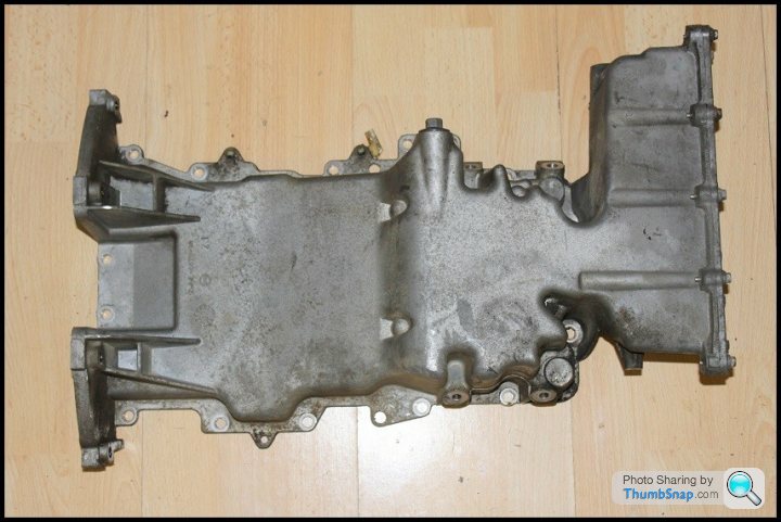
The fwd versions do not have this growth, plus it is slightly shallower too.
So for my AJ engine conversion, I decided to use the fwd Jag X type sump. But.....
One side of the sump hangs lower than the other. And when ground clearance is critical, I wasn't happy.
Anyone who knows the Jag AJ30 V6 engine, will know that in rwd format it has a strange growth on the front of the sump, I assume it's just to increase capacity, therefore increasing service intervals. It has a deep section too, not a good thing on the S !
The fwd versions do not have this growth, plus it is slightly shallower too.
So for my AJ engine conversion, I decided to use the fwd Jag X type sump. But.....
One side of the sump hangs lower than the other. And when ground clearance is critical, I wasn't happy.
Edited by Blue 30 on Wednesday 13th May 20:16
Edited by Blue 30 on Wednesday 13th May 20:16
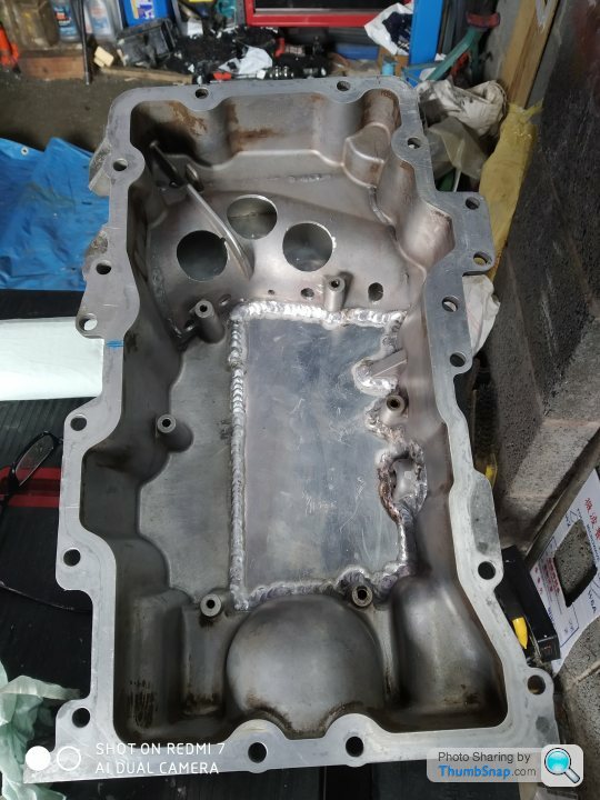
So my plan of action was to cut away 2/3rds across the bottom of the sump (the side that hangs low. Cut some flat alloy, and get it welded on. But being as I had some flat plate spare, why don't I add capacity by changing the design at the front of the sump. Doing the maths, I was loosing less than a pint, but gaining about a litre by the design change. It was one of the jobs where a specialist welder was required. Minus £50 later and it's done.
Old & new.
Plus I drilled through to the new section which will help with oil surge.
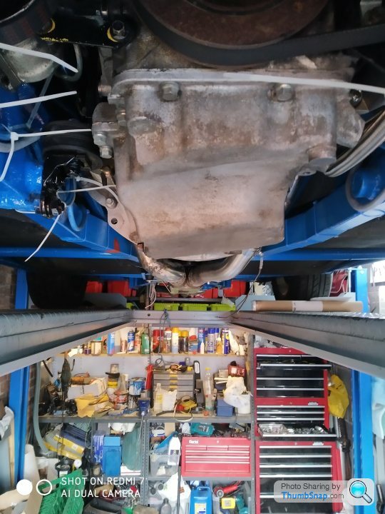
The oil pump pickup pipe just required a little fettling. And then back on the engine the sump goes.
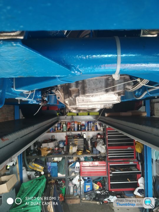
And it's now nice and level. At near enough the same level as the bottom of the main chassis rails. Yet the engine is mounted as low as possible hopefully maintaining a good centre of gravity.
Job done....
T.
Old & new.
Plus I drilled through to the new section which will help with oil surge.
The oil pump pickup pipe just required a little fettling. And then back on the engine the sump goes.
And it's now nice and level. At near enough the same level as the bottom of the main chassis rails. Yet the engine is mounted as low as possible hopefully maintaining a good centre of gravity.
Job done....
T.
Edited by Blue 30 on Wednesday 13th May 20:13
Edited by Blue 30 on Wednesday 13th May 20:19
Gassing Station | S Series | Top of Page | What's New | My Stuff