Discussion


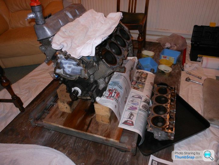
New years resolution, I must get going on the SEAC again! I've moved the original engine to my engine rebuild area; thinly disguised as my kitchen...

I will be replacing the cam, valve springs and collets plus anything else I find to be worn when I get the heads and the dry sump pan off. It's got solid lifters and so I suspect a very high lift cam; I'll pull it all out and see if I can identify it.
I will be replacing the cam, valve springs and collets plus anything else I find to be worn when I get the heads and the dry sump pan off. It's got solid lifters and so I suspect a very high lift cam; I'll pull it all out and see if I can identify it.
Warm, dry, dust free... what's not to like!!
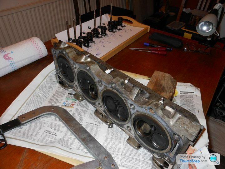
I've got the heads off now; quite easy with an improvised lever bolted to the engine to pull against - much easier than when I did the head rebuild on the 350i with the engine in the car.
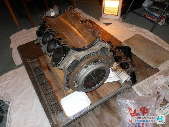
The rearmost cylinder on the LH bank is showing signs of steam cleaning so the head gasket was on it's way out.
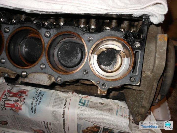
The gaskets are copper ringed composites (novel for '87?) with the bottom row of 4 bolts nipped up and not tight. The bore is just over 93mm and the stroke just over 77mm; so it's a 4.2 as suspected, but with a different bore to the later Rover developed 3.9/4.0s etc.
The valves are roughly dia42mm inlet and dia37mm exhaust; the largest that RealSteel quote on their website - I'm not sure what other RV8s use.
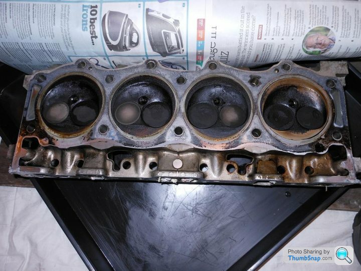
The bores look and feel perfect so I don't think it needs a rebore/pistons - phew!
I've got the heads off now; quite easy with an improvised lever bolted to the engine to pull against - much easier than when I did the head rebuild on the 350i with the engine in the car.
The rearmost cylinder on the LH bank is showing signs of steam cleaning so the head gasket was on it's way out.
The gaskets are copper ringed composites (novel for '87?) with the bottom row of 4 bolts nipped up and not tight. The bore is just over 93mm and the stroke just over 77mm; so it's a 4.2 as suspected, but with a different bore to the later Rover developed 3.9/4.0s etc.
The valves are roughly dia42mm inlet and dia37mm exhaust; the largest that RealSteel quote on their website - I'm not sure what other RV8s use.
The bores look and feel perfect so I don't think it needs a rebore/pistons - phew!
I'm glad folks are enjoying the thread; I'm enjoying working on the car too...
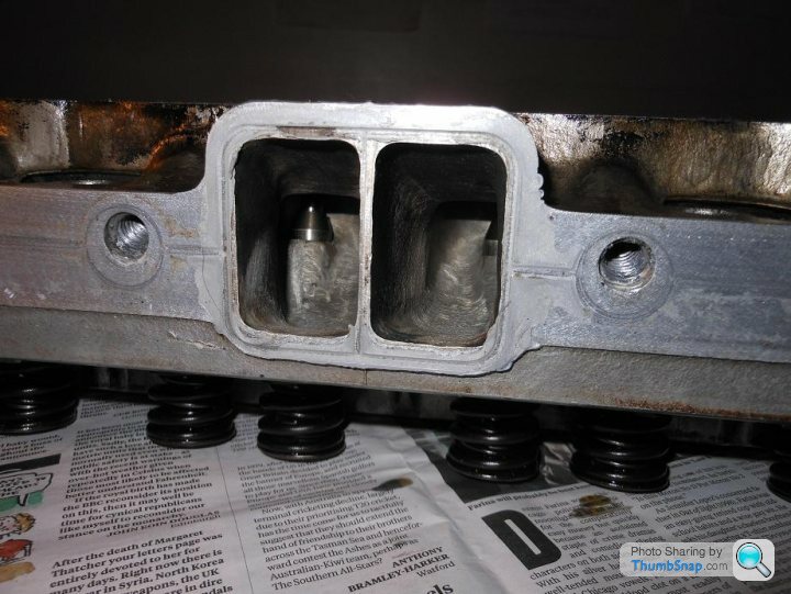
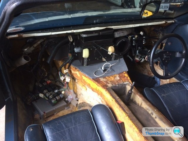
I'll take pics of the valve runners and throats when the heads are stripped, that shouldn't be long. The thin blade between the centre ports on my engine is the same as Ian's as you can see in this pic with the engine in the car:
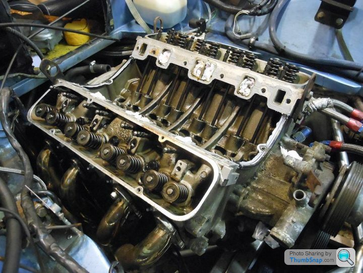
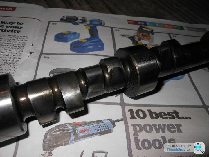
I've now got the cam out, it's heavily worn:
And wasn't difficult to identify:
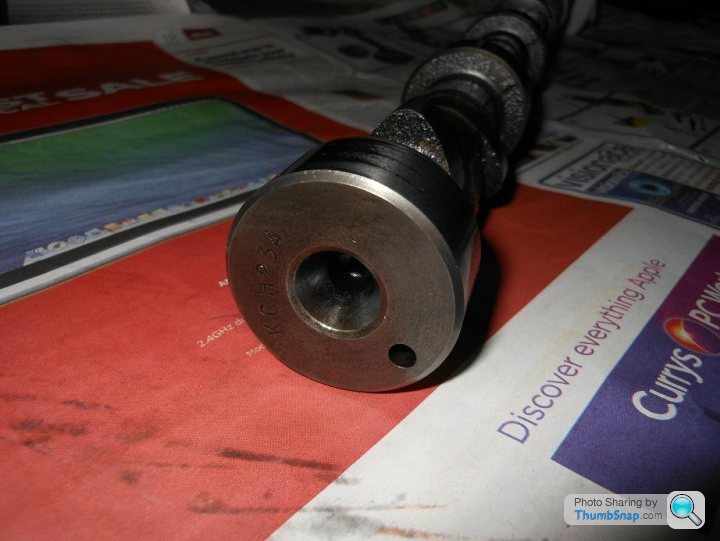
H234 but running solid lifters...hmmm!! Are there any experts out there who can explain that?
I'll take pics of the valve runners and throats when the heads are stripped, that shouldn't be long. The thin blade between the centre ports on my engine is the same as Ian's as you can see in this pic with the engine in the car:
I've now got the cam out, it's heavily worn:
And wasn't difficult to identify:
H234 but running solid lifters...hmmm!! Are there any experts out there who can explain that?
Hi Chris,
I hope things are going to plan in the states! I haven't decided what to do with the engine yet but one possibility is to rebuild using the same type of cam and follower that I took out; although it is a racing cam... Established wisdom is that it's intractable for the road but it is supposedly the cam used originally in SEACs. I assume (maybe foolishly!) that the rest of the engine/ECU/injectors/AFM/porting is set up for the 234 cam so it's quite tempting to replace like with like. Chris Schirle said the bottom end is balanced so at least it should like high rpms...
I hope things are going to plan in the states! I haven't decided what to do with the engine yet but one possibility is to rebuild using the same type of cam and follower that I took out; although it is a racing cam... Established wisdom is that it's intractable for the road but it is supposedly the cam used originally in SEACs. I assume (maybe foolishly!) that the rest of the engine/ECU/injectors/AFM/porting is set up for the 234 cam so it's quite tempting to replace like with like. Chris Schirle said the bottom end is balanced so at least it should like high rpms...
I've managed to extract the offending cam follower through into the block; it's pretty well worn and the edge is chewed up which explains it being unwilling to come out through the top:
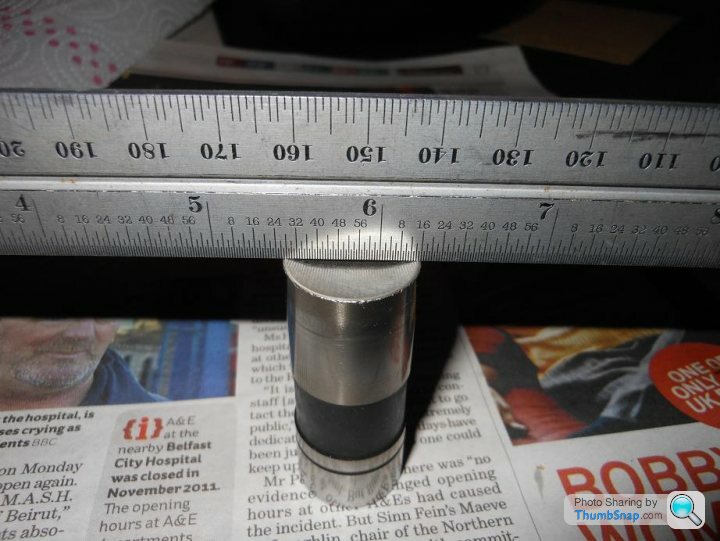
They are undoubtably solid lifters; they are hollow but there is a solid stack up between where the surface runs on the cam and the pushrod pocket.
I've started stripping the heads now, the porting is pretty extensive and the valve guides are a large diameter:
I've got most of the valve gear out of the first head, although two of the valve stems have slight burrs under the collet features and won't withdraw through the guides - slight work with a stone is needed. I'm not sure yet what the implications of this might be...
Edited by The Hatter on Sunday 12th January 21:43
Getting on with the heads, I got the valves out of the heads with a little dremmel assist. Clean up time, looking very good:
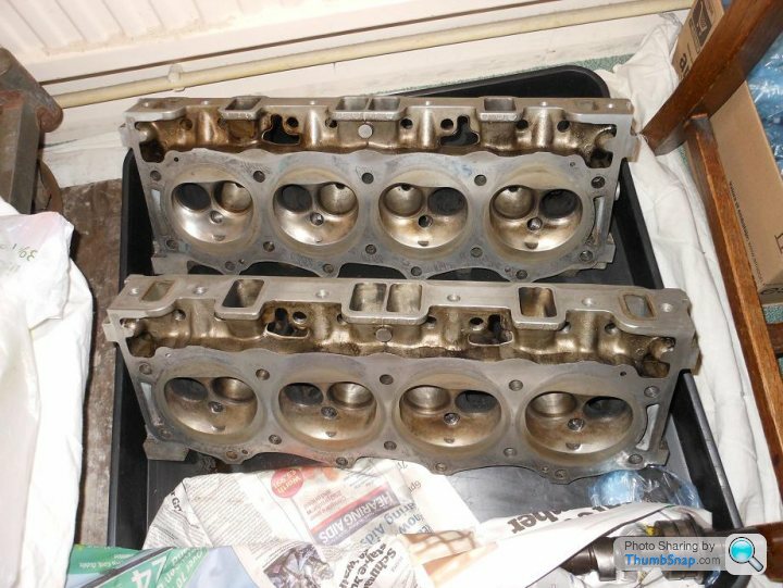
I'm not one for polishing the outside of an engine but I can get excited about the inside of an engine...sad!
Adam, I have the Hardcastle books, they're interesting reading...
Campbell, I'm leaning towards a rebuild using the same spec as original, though I'm thinking that a trigger wheel programmable ignition system would be wise... Food for thought!
Edited by The Hatter on Wednesday 5th February 22:30
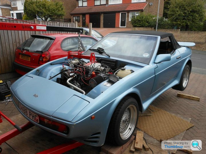
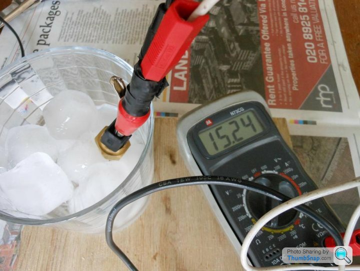
I've realised that I'm running out of time to get the original engine back into the car for this summer so I decided to put the car back on the road as it is with the surrogate 4.2 engine. I've not had it running very well so I thought I'd invest in an AFR meter to get the engine running properly:
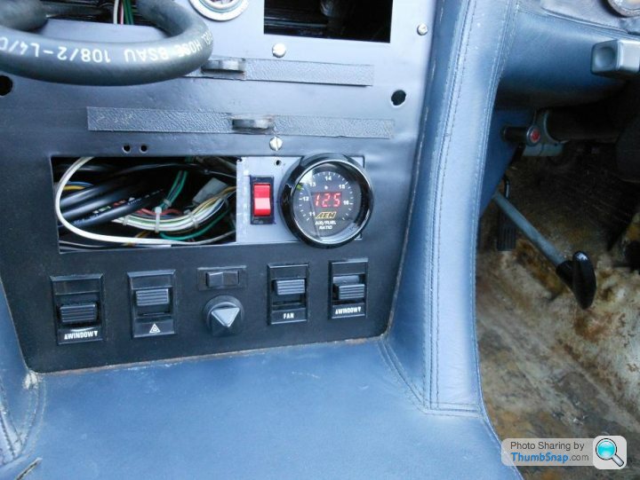
A wonderful investment; took me about 30 mins playing with the AFM to get something reasonable and it now drives very well. It was previously very rich at idle and very lean on part throttle so not surprisingly was coughing when the throttle was opened; it's now much smoother and I know the engine's not leaning out at the top end when floored.
So now I'm MOTed, insured and taxed and ready for the Burghley House 'do' in April...
Certainly worth having - to set up the engine. My plan is to remove it from the SEAC and rotate it around my other cars to check them out; if the SEAC starts misbehaving I'll re-install it. I'm watching the gauge like a hawk at the moment but I suspect I'll get bored of that!
When I had the exhaust made I got an M18 port put into each manifold just ahead of where they bolt up to the centre section. They're welded in such that the sensor is close to horizontal; that's against the installation guides for the sensors (they should be within 70 Deg of vertical to avoid condensation build up) but I figured I'd be installing them briefly rather than permanently so easy access was more important. I suspect that the proximity to the engine means the heat drives off the moisture anyway. I have some experience of these sensors at work and they are OK for short periods when not vertical.
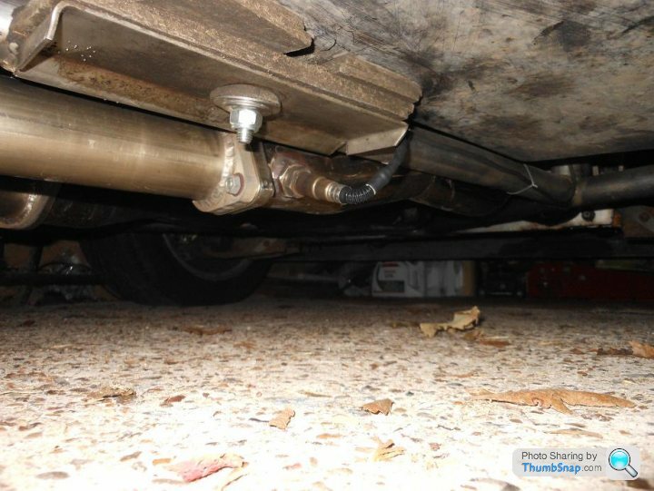
Looking at the car now I think it would be possible to install the sensor(s) vertically either side of the bellhousing; I'd do that if I was looking for a permanent install.
When I had the exhaust made I got an M18 port put into each manifold just ahead of where they bolt up to the centre section. They're welded in such that the sensor is close to horizontal; that's against the installation guides for the sensors (they should be within 70 Deg of vertical to avoid condensation build up) but I figured I'd be installing them briefly rather than permanently so easy access was more important. I suspect that the proximity to the engine means the heat drives off the moisture anyway. I have some experience of these sensors at work and they are OK for short periods when not vertical.
Looking at the car now I think it would be possible to install the sensor(s) vertically either side of the bellhousing; I'd do that if I was looking for a permanent install.
Time to work on the SEAC again as the winter sets in... I've been driving it about but getting first, third and fifth was getting a bit of a joke - the gearchange remote bushes were on their way out. They looked fine last time I had the engine out but apparently not.
So; polybushes to replace the dodgy rubber ones, two sets needed as on this car there seems to be extra ones on the top fixings which I guess pushes the gearlever rearwards and down. More importantly it would have fouled the centre console if I hadn't have replaced the bushes as I'd found them.
I thought it would be an easy-ish job from underneath, however the 'side' bolts on the remote linkage lined up precisely with the vertical chassis rails - which are closer together than a regular wedge due to the narrow central spine and wider seats. So there was no way I could get the bolts out without slinging the engine and moving it forwards a tad to be able to get the bolts out...
Easier said than done but I got there in the end!
Now into the next phase... plan is to get the original engine back into the car over the winter. I've been running the surrogate 4.2 with the flapper injection and an air/fuel ratio meter on the dash. It's apparent that the flapper is not very good at controlling the fueling. It's fine at full throttle and barks and pops like a demon, but at idle and part loads the fueling is way off. I'm very tempted by megasquirt; so I have bought a kit for the 350i to see how it goes...
I'm going to fit hotwire injectors (to get rid of the resistor pack), trigger wheel ignition, PWM cold start valve, Lambda sensor(s) and completely replace all the wiring. I'll then have fun and games tuning the thing on a laptop using the lamda sensor. If it's successful on the 350i then I'll probably fit it to the SEAC - and hopefully I'll be able to tame the race cam and solid lifter combo.
I'm finally looping around to working on the SEAC. The 350i is running superbly on Megasquirt so I'm going to go that route on the SEAC. It took alot of time, money and grief to get the 350i working properly but I'm now in a good position to put all the knowledge gained to good use.
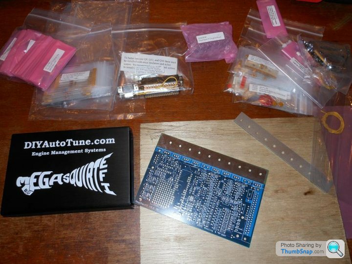
I bought a 'turn-key' kit for the 350i and it was a struggle all the way. I'm starting from scratch with the SEAC and have bought an un-built Megasquirt ECU from DIYAutoTune in the US. That way I can build the ECU to my own specification and have some faith in the unit and what it's doing.
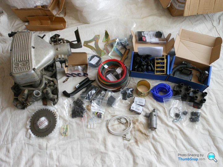
So now I have a megasquirt ECU kit; a megasquirt 'stim' (for testing the ECU); A megasquirt relay board to simplify the wiring and house the fuses; an innovate WB oxygen sensor kit; A Volvo PWM idle speed control valve; Ford EDIS 8 ignition box (replaces the distributor); wasted spark coils and leads from a lateish Range Rover; and a Rover V8 specific trigger wheel.
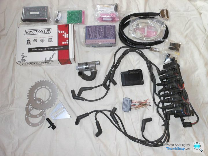
I'll also need to buy a load of connectors/wiring to build the loom; I've got some of that already, left over from the 350i. I still need to get some intake trunking, an air filter and an air temp sensor to replace the Flapper unit itself.
Time to get soldering and build the ECU...
I bought a 'turn-key' kit for the 350i and it was a struggle all the way. I'm starting from scratch with the SEAC and have bought an un-built Megasquirt ECU from DIYAutoTune in the US. That way I can build the ECU to my own specification and have some faith in the unit and what it's doing.
So now I have a megasquirt ECU kit; a megasquirt 'stim' (for testing the ECU); A megasquirt relay board to simplify the wiring and house the fuses; an innovate WB oxygen sensor kit; A Volvo PWM idle speed control valve; Ford EDIS 8 ignition box (replaces the distributor); wasted spark coils and leads from a lateish Range Rover; and a Rover V8 specific trigger wheel.
I'll also need to buy a load of connectors/wiring to build the loom; I've got some of that already, left over from the 350i. I still need to get some intake trunking, an air filter and an air temp sensor to replace the Flapper unit itself.
Time to get soldering and build the ECU...
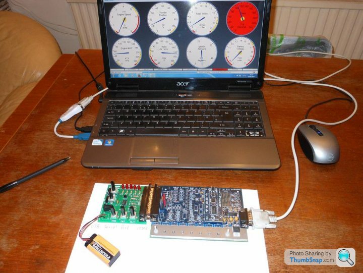
Getting going on the ECU now; got the power circuitry in place and checked.

The ECU is the blue board; the green board is a clever piece of kit that they get you to build first. The green board simulates the car; it sends signals to the ECU (engine speed, TPS, coolant temp, air temp and exhaust oxygen sensor) and then reads back the ECU outputs (ignition pulses, fuel injector pulses, fuel pump activation and idle control valve signal). You can twiddle the knobs to vary the inputs and see what happens to the outputs; plus you can monitor it all with the tuning software on a laptop so you can familiarise yourself with that aspect too.
I also have the very big advantage of being able to plug the ECU I'm building onto the 350i, so I can be sure it's all OK before attempting to run the SEAC with it.
Getting there... the ECU is now finished:

and tested on the bench:
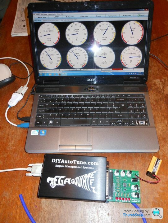
The gaps on the circuit board are meant for circuits I don't need; like the crankshaft trigger wheel sensor circuits and the coil drivers (both of which I'm handling with the Ford EDIS system).
Next step is to plug this ECU into the 350i that's already running Megasquirt and see how it behaves. The 350i was running MS1 and this new one is MS2 so there are differences; I've already noticed how much better the online documentation is for the MS2 which should help setting up and tuning.
and tested on the bench:
The gaps on the circuit board are meant for circuits I don't need; like the crankshaft trigger wheel sensor circuits and the coil drivers (both of which I'm handling with the Ford EDIS system).
Next step is to plug this ECU into the 350i that's already running Megasquirt and see how it behaves. The 350i was running MS1 and this new one is MS2 so there are differences; I've already noticed how much better the online documentation is for the MS2 which should help setting up and tuning.
The yellow wires are needed to add a beefed up transistor to the idle control circuit.
The standard board will run a stepper motor or an on/off idle valve through a relay. The transistor that is connected to the yellow wires will allow me to run a PWM idle valve in closed loop control - so I should be able to hold a desired idle speed under all conditions.
The standard board will run a stepper motor or an on/off idle valve through a relay. The transistor that is connected to the yellow wires will allow me to run a PWM idle valve in closed loop control - so I should be able to hold a desired idle speed under all conditions.
I've been running the MS2 on the 350i for the last couple on months; it's superb, much better than the MS1 I was running before. So much so, that I've decided to bin the 350i MS1 and build another MS2 so I can have the 350i and the SEAC both running the same ECU and tuning software.
So now at long last I'm getting back onto the SEAC. The megasquirt unit needs an inlet air temperature sensor which I've decided to put in the location vacated by the now redundant cold start injector. I don't want to do anything that would change the car and stop me returning it to a flapper configuration if I need/decide to, so I searched for an air temperature sensor that would fit through the small diameter hole that the cold start injector goes through. It's a BMW sensor, and I chose to make an adaptor piece so that I don't have to drill/tap the original SEAC plenum:
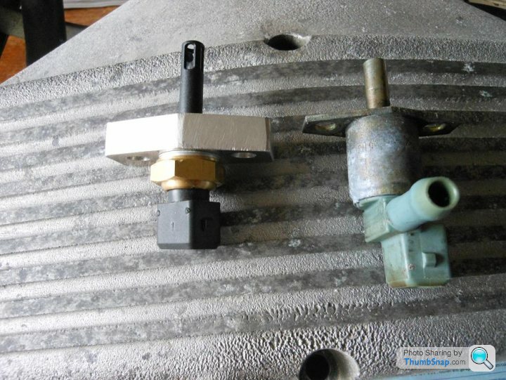
I now have to work out the calibration of the sensor so that the Megasquirt can convert the sensor output resistance to a temperature value - cue shannanigans with ice, boiling water and somewhere in between to get a three point approximation to the logarithmic curve of the sensor...
To answer Chris' question, the MS2 will drive the hotwire stepper motor if so desired, but I'll be using a Volvo idle speed control valve made by Bosch.
So now at long last I'm getting back onto the SEAC. The megasquirt unit needs an inlet air temperature sensor which I've decided to put in the location vacated by the now redundant cold start injector. I don't want to do anything that would change the car and stop me returning it to a flapper configuration if I need/decide to, so I searched for an air temperature sensor that would fit through the small diameter hole that the cold start injector goes through. It's a BMW sensor, and I chose to make an adaptor piece so that I don't have to drill/tap the original SEAC plenum:
I now have to work out the calibration of the sensor so that the Megasquirt can convert the sensor output resistance to a temperature value - cue shannanigans with ice, boiling water and somewhere in between to get a three point approximation to the logarithmic curve of the sensor...
To answer Chris' question, the MS2 will drive the hotwire stepper motor if so desired, but I'll be using a Volvo idle speed control valve made by Bosch.
Hi Adam,
I can only go by my personal experiences and some people swear by MS1; my opinion of MS1 has been tarnished by buying a supposed 'turn-key' Rover V8 kit that was anything but. My opinion is that MS1 was originally designed as fuel-only (no spark control) where MS2 does both. I bought an MS1 that had been modifed internally (unbeknown to me at the time) such that it would control spark and fuel - and I had persistent problems with noise on the tach signal. If the engine speed is read incorrectly clearly the fueling will be way off, so I had regular hiccoughs. I spent ages working with various ways of getting rid of the noise (aided by people who really know their stuff) and got nowhere. When I ran MS2, built how B+G intended, the noise vanished.
It's now clear to me that MS1 is outdated technology, most of the documentation and forum advice out there relates to MS2 - I think that's because everyone's reached the conclusion that MS2 is far better! MS3 is generally for more modern engines with variable cam timing that could benefit from sequential fueling, there's little or no benefit in using MS3 on a 2 valve/cyl pushrod V8.
There's also microsquirt; but that was developed for snowmobiles and chainsaws and the like; I'm not sure of the wisdom of running a Rover V8 on one. In any case a microsquirt wouldn't run the 'flapper' injectors although it should be OK with hotwire (high impedence) ones.
It's also worth noting that contrary to some websites selling MS stuff, you NEED a wide band lambda sensor and you NEED to buy the tuning software to be able to tune the engine properly (ie better than 80% there). There are free versions of the software available but the free versions will severely limit your capability to tune.
Hi Stewart,
I'm sure there's better qualified people to answer that question but I don't see why not. My engine is running a speed/density algorithm which may be problematic with one throttle per cylinder; but megasquirt can also run an 'alpha-n' algorithm where it just looks at throttle position and engine speed and calculates the fueling from that. I suspect it would run fine at high loads and sound fabulous, but not be so great at low revs/load.
MS can also run with an air flow sensor, but again that would be awkward and not very efficient with eight throttles...
Oops, nearly a year and I've not done anything to the car! Other than drive it of course... The heater fan started generating burning smells so the dashboard had to come out again last weekend to change the fan.
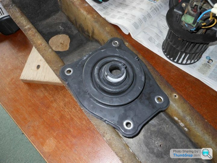
I took the oportunity to put a gaiter around the gearlever; originally the car had two sheets of rubber optimistically placed over the gearlever and they were never going to seal, so I butchered a mk2 MX5 gaiter and made it fit with the help of some high temp silicon sealer.
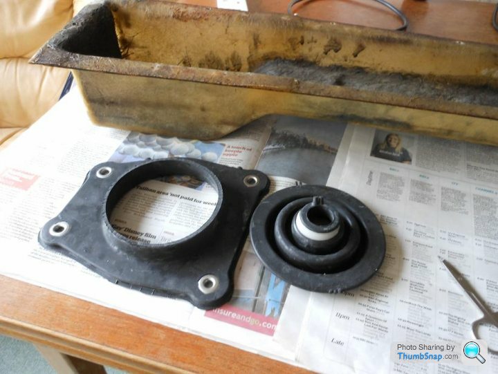
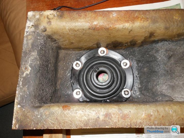
It fits and works very well with no restriction to the gear lever movement. I reckon it would work on the 350i too.
I'm planning to tidy up the interior a little (not a lot!) and prepare the wiring for Megasquirt.
I took the oportunity to put a gaiter around the gearlever; originally the car had two sheets of rubber optimistically placed over the gearlever and they were never going to seal, so I butchered a mk2 MX5 gaiter and made it fit with the help of some high temp silicon sealer.
It fits and works very well with no restriction to the gear lever movement. I reckon it would work on the 350i too.
I'm planning to tidy up the interior a little (not a lot!) and prepare the wiring for Megasquirt.
Gary, the 350i gaiter wouldn't fit, even if I could find one... the SEAC is completely different in the transmission tunnel area because of the narrow central chassis, that's why the handbrake is under the dash, and probably why there's a removable panel. I'm not sure if other SEACs had that panel, I think TVR were making it up as they went along. Also not sure what you mean by a cup, Mark, but the gear lever mechanism is the same as the 350i.
Gassing Station | Wedges | Top of Page | What's New | My Stuff