Wedge Under Bonnet Pics
Discussion


John042 said:
Happy returns by the way.  I thought I was the oldest on this forum?
  John C.
Im only 53 years young..Although sometimes it feels like 503...I used to think i had really bad creaky wooden floors but after having the whole house rebuilt we realised it was me creaking...Oh well... I thought I was the oldest on this forum? John C.RCK974X said:
No worries mate, rick from "RCK" ? I can be happy with that..... 
me too, the 'big six' isn't far away ...
See , Zig's pics are already slightly different to mine - he appears to have a 'T' piece at top of engine, whereas mine has an elbow (1/2 inch) with a small separate outlet (1/4 or 3/16" ish) which goes off to the overflow tank.
So you'll have to accept that your particular installation may vary in the detail !!
As I said Ford did change some of the detailed bits over time, there are even two engine block versions - externally identical but they have different camshaft bearings....
Do you want a pic of the hoses on mine ??
The pics i posted up recently were a friends 280i..Cant remember what reg his is but i don't think there was much in it between him and Delilah, It might help if anyone else with a 280i could post up pics..In fact if John posts up the hoses that he is stumped on then it might be easier for us to identify where they go...Or not...As the case may be...me too, the 'big six' isn't far away ...
See , Zig's pics are already slightly different to mine - he appears to have a 'T' piece at top of engine, whereas mine has an elbow (1/2 inch) with a small separate outlet (1/4 or 3/16" ish) which goes off to the overflow tank.
So you'll have to accept that your particular installation may vary in the detail !!
As I said Ford did change some of the detailed bits over time, there are even two engine block versions - externally identical but they have different camshaft bearings....
Do you want a pic of the hoses on mine ??

He might just randomly be picking up bits of hose he has laying around in his garage...And saying..."So wheres this fugging go then"...

Edited by mrzigazaga on Monday 10th August 22:08
You hit the nail on the head Zig, "bits of hose lying around from the previous owner" As this project progress I'm made well aware that the past owner "collected" parts, not necessarily from the same vehicle! It started with the engine rebuild, different timimng case, water pump and has progressed through steering rack/alternator etc. I visited "Wesley" last night armed with Andy's pics. I've got a "T" assembly of hoses, which seem to live on top of the engine. That leaves the two heater hoses,(One down to the rear of the thermostat housing, the other to a valve on the drivers side of the plenum?) Two connections to the top of the header tank. One to a connection on the radiator, (If there is one) the other conection an overflow? I still have another assembly of hoses joined together with another "T" piece! I think more pics needed.
  John C.
It started with the engine rebuild, different timimng case, water pump and has progressed through steering rack/alternator etc. I visited "Wesley" last night armed with Andy's pics. I've got a "T" assembly of hoses, which seem to live on top of the engine. That leaves the two heater hoses,(One down to the rear of the thermostat housing, the other to a valve on the drivers side of the plenum?) Two connections to the top of the header tank. One to a connection on the radiator, (If there is one) the other conection an overflow? I still have another assembly of hoses joined together with another "T" piece! I think more pics needed. John C.John...Please post up the hoses you have that you are not sure where they go..I have been trying to find pics of the coolant hose layout of a Ford capri mk3 2.8i V6 cologne...But i cannot find any..I did know the route of all the hoses at one point but its been a while and without looking its not easy...I might be going to the ford garage this week so will take pic of the coolant hoses...You will get there eventually....
John042 said:
Cheers Zig. Will pay "Wesley" a visit this evening. Am I right in assuming the TVR heater system did not have a water control valve? Coolant constantly flowing through the heater matrix, and used a flap system to divert air either over the matrix or not? John C.
Thats correct mate...In fact i by-passed mine as i never needed to use hot air, Even in January ... That would get rid of two chuffing pipes.
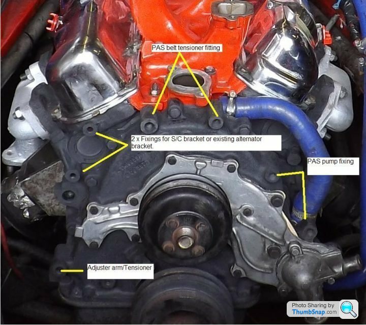
John i have been thinking about this most of the day so i hope its right...I think the only thing i got wrong was the flow direction!...Don't confuse the air/Vacuum hoses with the water for now...The AAD plate is mounted on the plenum and should have 3 x Openings..Two together at the top around 9mm and one around 15mm at the bottom...Which goes to the right hand side heater matrix opening..Im talking as if you are standing in front of the car looking straight at it, Steering wheel on your left so speak...
The Auxiliary air device is bolted to this plate so that the water heating up aids the air for cold start.
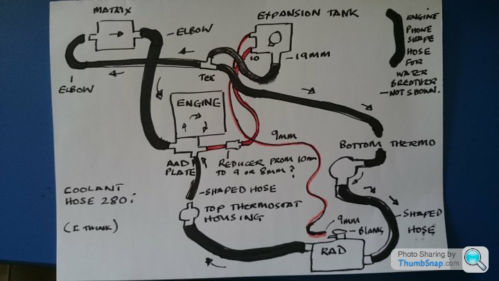
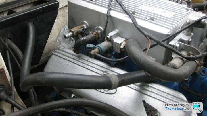
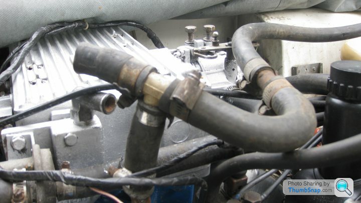
The hose i haven't drawn in...The telephone shaped one is for the water from bottom to top of engine...As in this pic...
So here we go....Click the picture once and then again once it has loaded up...(You should also be able to drag and drop it onto your desktop)
We will deal with the air hoses in a bit...
Actually just remembered...The 19mm in the pic is 15mm ID hose ...The 10mm on the tank is actually 12mm ID hose...I remember buying a 10mm ID hose with an OD of 13.5mm in silicone...And one of the top AAD plate inlets are 15mm as well as a 9mm...
Take no notice of the black hose that is what looks like bending up towards the PAS pump..Thats an air hose....The blue one from the throttle body is also a vacuum so ignore that.
The Auxiliary air device is bolted to this plate so that the water heating up aids the air for cold start.
The hose i haven't drawn in...The telephone shaped one is for the water from bottom to top of engine...As in this pic...
So here we go....Click the picture once and then again once it has loaded up...(You should also be able to drag and drop it onto your desktop)
We will deal with the air hoses in a bit...
Actually just remembered...The 19mm in the pic is 15mm ID hose ...The 10mm on the tank is actually 12mm ID hose...I remember buying a 10mm ID hose with an OD of 13.5mm in silicone...And one of the top AAD plate inlets are 15mm as well as a 9mm...
Take no notice of the black hose that is what looks like bending up towards the PAS pump..Thats an air hose....The blue one from the throttle body is also a vacuum so ignore that.
Edited by mrzigazaga on Tuesday 11th August 16:15
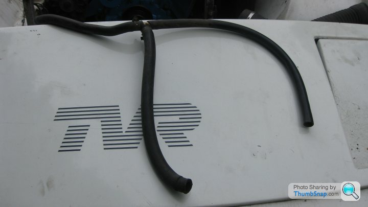
Thanks Zig that drawing will help in finding the correct passage of coolant. As promised, I 've attached the two pipe setups that came with the car. Both with "T" pieces. One seems fit on the top of the engine block with a longer pipe heading to the expension tank. I thought to the bottom of the tank but it's not the right size. I'm not sure about other "T" piece with pipes connected, maybe not from this engine? The nearside heater pipe seem to fall naturally to the rear thermostat housing. The drivers side heater pipe again seems to fit onto the valve at the top of the engine. Correct or not? Thanks again for time and patience. John C.
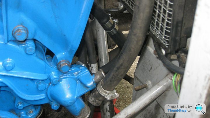
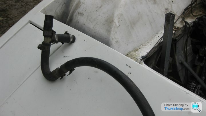
Hi John...A couple of things...In the pic of the pipe hanging down to the thermostat housing..Which bit of hose was that?...If its the one with the tee in then thats right..Then one end goes to the other matrix inlet and the other goes to the bottom of the expansion tank..Personally i would buy new hose and ditch that old rubbish once you know where it goes...You could follow my drawing as i know its right?...
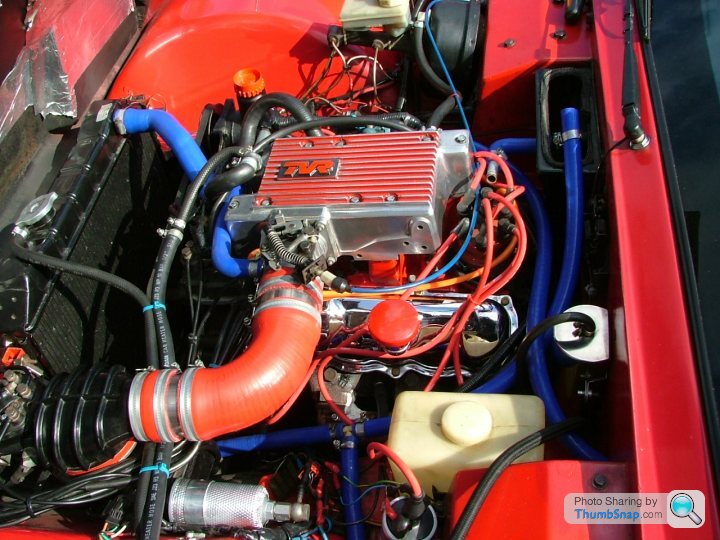
Also the O/S rocker cover looks wrong as the crankcase breather is supposed to vent into the plenum via the rocker cover...Do you have any other rocker covers?....
Also the O/S rocker cover looks wrong as the crankcase breather is supposed to vent into the plenum via the rocker cover...Do you have any other rocker covers?....
Thanks Zig. No, the large pipe hanging down by the thermostat. is from the heater matrix, nearside. So early I repositioned that pipe around the rear of the engine to the valve on the pleum casing drivers side. The other heater pipe, I repositioned again around the rear of the engine to the nearside. This I think I can connect to the T piece I already have, as those connections then fit to the expansion tank and down to the rear thermostat.. That would. match your diagram? The other T connect looks correct on the top of the engine? I'm not sure about the breather pipe? Is that the small right angled rubber pipe from the pleum, drivers side? The two rocker covers, alloy ones, I thought were a set? I have, what might be the original ones which are the usual tin ones. Look horrible! If that pipe is a breather can I modify the offside rocker cover? I believe there is already a very small union. (1/8") in the top of the cover. Yes I will be replacing the old hoses. Thanks again Mate, I think there's light at the end of the coolling tunnel. John C.
Thanks Andy for the offer of more pics but I think Zigs lastest flow diagram more or less cracks it making sense at last. I'm glad you confirm that it more or less follows your layout. Anyway, I thought water flowed the other way in the Southern hemisphere? Coriolis effect and all that.  Sorry, early morning humour Andy. However you've confirmed yet another part of my purchase being from an EFI engine; the alloy rocker covers. That i/2" right angled rubber union from the offside plenum is a breather which connected into the original o/s rocker cover? On the alloy cover there is a very small pipe union, perhaps I can modify that? Other than that pipe I can't see any other breather from the rocker covers. One step forward and all that.
 Only two more questins, not related to coolant systems. Can PAS pump drive shaft seals be replaced? What size battery do I need to fit offside by the brake servo please? Many thanks Andy. John C.
Sorry, early morning humour Andy. However you've confirmed yet another part of my purchase being from an EFI engine; the alloy rocker covers. That i/2" right angled rubber union from the offside plenum is a breather which connected into the original o/s rocker cover? On the alloy cover there is a very small pipe union, perhaps I can modify that? Other than that pipe I can't see any other breather from the rocker covers. One step forward and all that. Only two more questins, not related to coolant systems. Can PAS pump drive shaft seals be replaced? What size battery do I need to fit offside by the brake servo please? Many thanks Andy. John C.John042 said:
Can PAS pump drive shaft seals be replaced? What size battery do I need to fit offside by the brake servo please?
Hi John...I meant to say about the pump...Yes it can be refurbished...I use these guys...https://www.google.co.uk/url?sa=t&rct=j&q=...
They have branches up your neck of the woods too....
Q: What battery fits into the tiny space allocated by TVR...
A: A very good question......
You will have to measure exactly how much space you have..I had to go for an MX5 gel battery as it was one of the only ones with enough CCA to crank the engine..(450CCA). and was affordable..Just about....There are other batteries but they are racing red tops etc and not cheap!...
Hope this helps....Ziga
Thats good news mate...But if you are unsure just ask..I have been looking to see if i could find you any rocker covers, Im no expert on this but I'm pretty sure there is a particular calculation for the components of the crankcase breather system...Meaning that in relation to pressure there is a balanced breather which sucks in air from the filler cap goes round the crank and is drawn up through the PCV valve by the vacuum in the plenum...The oily air is burnt off...I was going to install a catch tank on mine when we were supercharging it but we needed to maintain crankcase breather pressure which got a bit complicated...I should imagine boring the correct size hole in the existing rocker cover shouldn't be a problem as long as its the same size as what the cologne covers had...You might need these for that little stubby pipe coming off the plenum...Oh and don't loose the little yellow pipe clip as they are perfect.
http://www.ebay.co.uk/itm/New-PCV-Valve-Ford-Model...
Not sure if the refi covers have drilled holes but i would certainly put them into the equation when considering drilling for the breather...Would be a sight easier with the cologne covers...
http://www.ebay.co.uk/itm/New-PCV-Valve-Ford-Model...
Not sure if the refi covers have drilled holes but i would certainly put them into the equation when considering drilling for the breather...Would be a sight easier with the cologne covers...
Gassing Station | Wedges | Top of Page | What's New | My Stuff