18 Volt Cranking Circuit Diagram Here
Discussion


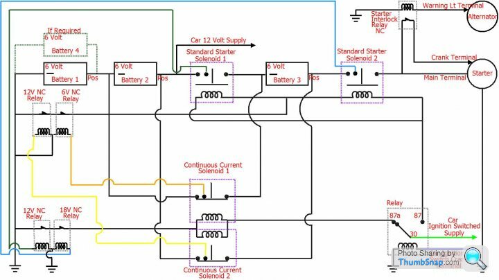
I have now finished this circuit that will give 18 Volts to the starter motor when cranking from the ignition switch, included in this circuit are 4 relays that will ensure that none of the batteries can short circuit and cause a fire should any one of the 4 solenoids contacts weld closed , many thanks to Max_Torque for pointing out the safety issues with my original diagram, I have also added a 5th relay to protect the starter motor should there be a failure and a permanent 18 Volts is supplied to the starter and crank terminal. The solenoids used all have a third contact that is normally used for a 12 Volt supply to a ballast resistor circuit, I have utilised this third contact to operate the safety relays
I will leave my original post and diagram here below. Thank you to those that gave good input
Please, I need your opinions on this diagram. Although I have titled this topic "18 Volt Cranking" it gets better than this, I have calculated a voltage of approximately 14.8 / 15 volts at the starter motor during cranking and believe this will have no drastic effect on the starter motor or its solenoid if put into long term use
Obviouly all the cables from the batteries to the solenoids contacts are of the heavy duty battery cable type
The diagram is drawn to show the circuit with ignition on, when cranking the relay will switch in and the two continuous current solenoids will drop out followed by the two standard starter solenoids pulling in. Battery 3 is in parallel with battery 2 and they are in series with battery 1 when the engine is running and they all charge from the vehicle alternator. During cranking battery 3 is in series with batteries 1 and 2 and 18 volts is supplied to the starter motor, this voltage obviously drops once the starter motor kicks in
Battery 4 if fitted would aid in balancing the batteries out (2 x banks of 2 parallel connected 6 Volt batteries connected in series with eachother will improve the charging conditions and give a better battery life)
I am aware of the fact that there would be a problem if at least one particular solenoid did not drop out before the other pair pulled in and I will be adding a fix for this tomorrow
Thank you in advance
Edited by Penelope Stopit on Tuesday 18th July 18:23
[quote=Penelope Stopit]Please, I need your opinions on this diagram. Although I have titled this topic "18 Volt Cranking" it gets better than this, I have calculated a voltage of approximately 14.8 / 15 volts at the starter motor during cranking and believe this will have no drastic effect on the starter motor or its solenoid if put into long term use
Obviouly all the cables from the batteries to the solenoids contacts are of the heavy duty battery cable type
The diagram is drawn to show the circuit with ignition on, when cranking the relay will switch in and the two continuous current solenoids will drop out followed by the two standard starter solenoids pulling in. Battery 3 is in parallel with battery 2 and they are in series with battery 1 when the engine is running and they all charge from the vehicle alternator. During cranking battery 3 is in series with batteries 1 and 2 and 18 volts is supplied to the starter motor, this voltage obviously drops once the starter motor kicks in
Battery 4 if fitted would aid in balancing the batteries out (2 x banks of 2 parallel connected 6 Volt batteries connected in series with eachother will improve the charging conditions and give a better battery life)
I am aware of the fact that there would be a problem if at least one particular solenoid did not drop out before the other pair pulled in and I will be adding a fix for this tomorrow
Thank you in advance
There seems to be some misunderstanding here
I am asking for opinions about my diagram as in, do any of the technical people that visit this forum see anything that I have overlooked
As previously mentioned, I have spotted a possible problem that may arise if there was a conflict in the timing of certain solenoids dropping out when others are pulling in and will later post the fix for this
Should any member with much automotive electrical technical knowledge visit this topic, will you kindly look over my diagram and point out anything that I may have overlooked.
Thank you in advance
I haven't put my time into this so as to suffer the ignorance of some members that have posted here
phillpot said:
As this is far from TVR specific maybe you'd be better off clogging up asking on a more general forum?
The chances are that I am well off the mark here, I get an inkling that you don't like meeliot said:
Steve_D said:
I can't claim to know much about electrics but you may get a better response from those that do if you were to describe what you plan to use this circuit for and why you think it is required.
As a general observation from a TVR standpoint I can't see why it would be required, it would add considerable weight and cost a pretty penny.
Steve
Exactly.As a general observation from a TVR standpoint I can't see why it would be required, it would add considerable weight and cost a pretty penny.
Steve
O/p what problem are you trying to solve and on what car?
_____________________________________________________________________________________________________________
Max_Torque said:
I know TVR owners like to mess around and modify their cars, but in this case i can;t see the point?
If your car doesn't start with a normal 12v battery and starter, the engine's f**ked. Fix the engine, don't modify the car to try to mask a failure!
All this extra wiring and contactors is likely to be a) highly unreliable and b) a massive fire risk when, inevitably, one relay gets a bit sticky, or contact welds on.....
Can you explain why you need 18V to start the engine??
This all started with me looking at starting circuits that are already in use but could be improved, I appreciate that many engines shouldn't need any extra help, this set-up is for one off modified engines with high compression and/or slow cranking problems caused by design not faults
You mention "fire risk" and I do agree that this is a big problem, I will need to take a closer look into the switching side of this and how to monitor the solenoids pulling in and dropping out so as to make them failsafe or possibly add a safety fuse
Thank you for your post
_______________________________________________________________________________________________________________
Due to some TVR enthusiasts building high performance engines with high compression and possible slow cranking problems I thought I would post my diagram here, most uprated cranking circuits are 24 Volt and I reckon this voltage is damaging starter motors and solenoids
phillpot said:
Penelope Stopit said:
The chances are that I am well off the mark here, I get an inkling that you don't like me
It's not that I dislike you Penny, I don't even know you. It's more a matter of respect. Rather than all your theoretical "brain waves", if you could come on here with just one tried and tested solution for a known issue that you had come up with and fitted to your car then myself (and possible one or two others) may take interest.The problem was.......
I did this........
No issues since

The tongue-in-cheek figure of speech is used to imply that a statement or other production is humorously or otherwise not seriously intended, and it should not be taken at face value.
The phrase was originally meant to express contempt. By 1842, however, the phrase had acquired its contemporary meaning, indicating that a statement was not meant to be taken seriously
TwinKam said:
Penelope said:
...most uprated cranking circuits are 24 Volt and I reckon this voltage is damaging starter motors and solenoids
I don't think this is the case. We never burnt one out. Best ask the current crop of rally boyos if they still do it.If it is a real concern to you, why not substitute a 6v battery for the !2v 'starter battery' in magpies' diagram a few posts above?
I am aware of 24 volt starting on Ford Escort BDA's, Ford and other rally teams were not concerned about hammering the starter motors, rally cars are not stopping and starting day in/day out
Thanks for your suggestion of modifying Magpies diagram but it isn't as easy as that otherwise I would have done it, I have used 6 Volt batteries because the switching can be arranged to charge the battery that is being used to up the voltage to 18 Volts and as I have already mentioned, 18 Volts is plenty and the starter doesn't get hammered
24 Volts starting is easy and this is why it is often used but it does hammer a 12 volt starter, see the below series parallel solenoid

Taken from here http://www.ebay.com/itm/New-Solenoid-SERIES-PARALL...
These will supply 24 Volts to a 24 Volt starter yet hammer a 12 Volts starter
This is all about engines/starter motors in everyday use
Thank you for your input
ChimpOnGas said:
Penelope Stopit said:
Penelope Stopit (or whoever you are), If you want a serious starter system you need to forget batteries altogether and take a leaf out of Kenworth's book....
https://www.youtube.com/watch?v=7t6zdQKsYs4
I was working for the NZ Forestry Corporation in Rotorua in the 90's when I first came across Kenworth Airstart, and I can tell you it made me properly jump out of my skin when it spun up

Truth is my TVR needs none of this, with my upgraded starter cable and earth return, Odyssey PC1500 850cca AGM battery, and £62.00 Global Power Disco 1 V8 starter motor my Chimaera engine spins up like you'd never believe.
That 18v starter circuit looks like a certain keen hobbyist has got way too much time on his hands solving problems that just don't exist

Retirement must be sooooo dull

I have not and never will have anything to post in your direction in the future unless it suits me to, being what you are, your above comments are to be expected
PS I never use the report button and never will do
ChimpOnGas said:
Penelope Stopit said:
ChimpOnGas said:
Penelope Stopit said:
Penelope Stopit (or whoever you are), If you want a serious starter system you need to forget batteries altogether and take a leaf out of Kenworth's book....
https://www.youtube.com/watch?v=7t6zdQKsYs4
I was working for the NZ Forestry Corporation in Rotorua in the 90's when I first came across Kenworth Airstart, and I can tell you it made me properly jump out of my skin when it spun up
Truth is my TVR needs none of this, with my upgraded starter cable and earth return, Odyssey PC1500 850cca AGM battery, and £62.00 Global Power Disco 1 V8 starter motor my Chimaera engine spins up like you'd never believe.
That 18v starter circuit looks like a certain keen hobbyist has got way too much time on his hands solving problems that just don't exist
Retirement must be sooooo dull
I have not and never will have anything to post in your direction in the future unless it suits me to, being what you are, your above comments are to be expected
PS I never use the report button and never will do
Even thought it appears likely you've never even sat in a TVR let alone owned one, no doubt you'll be equally free with help when you're besieged with people wanting to give their TVR 18v starting

 thole of a world that we live in, after food of course
It looks like I'll need to alter this diagram, at the time of my drawing of this diagram I didn't know that some manufacturers including Bentley were already using 48 Volts for some circuits
https://www.theverge.com/2017/8/29/16216158/bentle...
https://www.extremetech.com/extreme/247889-cars-mo...
Electric Turbo https://www.johnsonelectric.com/en/features/electr...
Live and learn hey
Have a good evening and a Relay Happy New Year
https://www.theverge.com/2017/8/29/16216158/bentle...
https://www.extremetech.com/extreme/247889-cars-mo...
Electric Turbo https://www.johnsonelectric.com/en/features/electr...
Live and learn hey
Have a good evening and a Relay Happy New Year
Edited by Penelope Stopit on Monday 31st December 19:10
Gassing Station | General TVR Stuff & Gossip | Top of Page | What's New | My Stuff