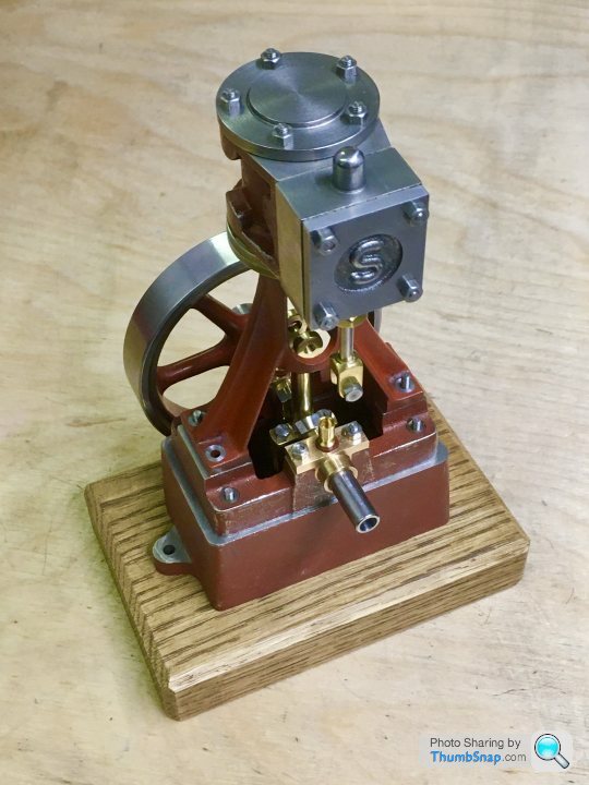
Stuart 10V Vertical Steam Engine
Discussion


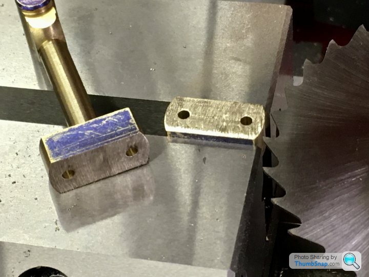
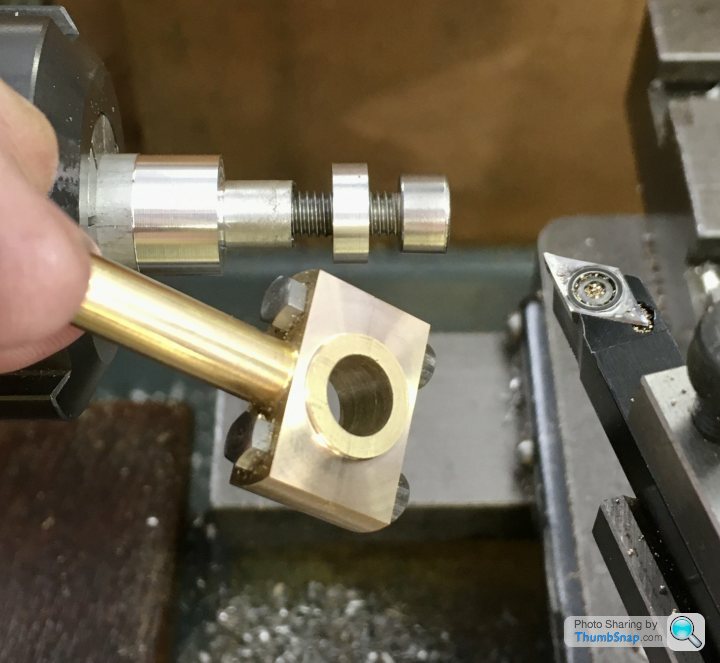
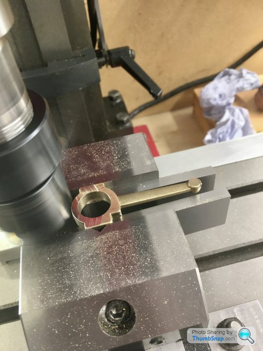
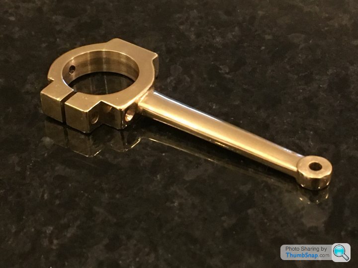
Connecting rod next. I believe it used to be supplied as a stamping, but now it’s a rough-machined item:
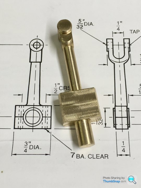
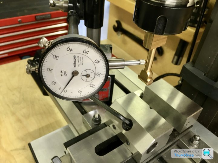
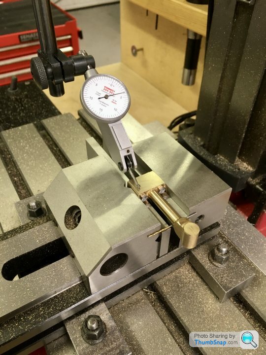
For some reason, it’s got a spigot on the back. I used it to locate in the mill collet, and then lowered into the vice in preparation for drilling the bolt holes. I clocked it up beforehand to check it was straight; it wasn’t bad, a few thou runout:
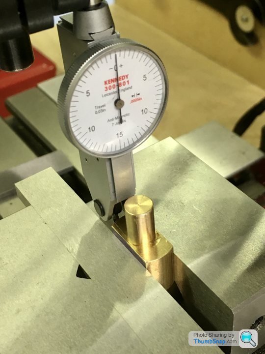
And again in the vice to check all the accessible surfaces were square:
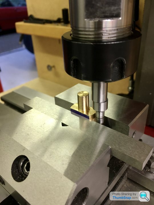
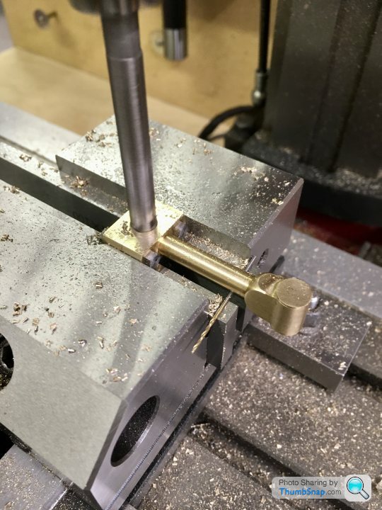
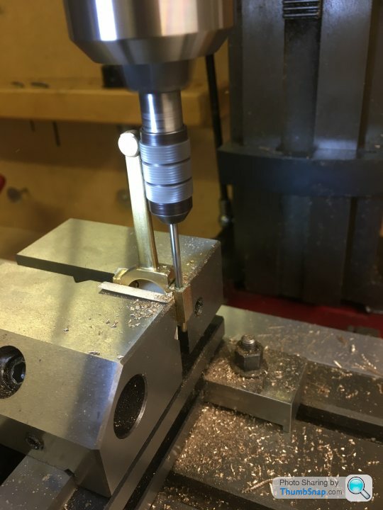
I then used the edge finder to centre the spindle:

Then co-ordinate drilled the holes. I used a smaller drill than specified in order to get a tighter fit:
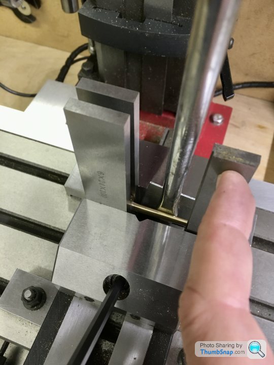
Then removed from the vice, marked out the split line, and the-fitted in the vice to check its level:
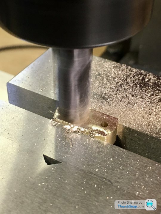
Then used the thin slitting saw to cut the lower block:
Then cleaned up the mating faces with an end mill:
And removed the spigot from the lower block and milled to the correct depth:
Bolted together and Loctited, the sides were milled to the right thickness to fit between the crank webs:
And the small end faces. A bit of vibration here, but I couldn’t think how else to hold it to drill bothe ends in the same setup:
Then double checked the main faces for flatness in two planes:
Then got the centre point for the crank pin hole bang on the cut line:

Drilled and reamed:
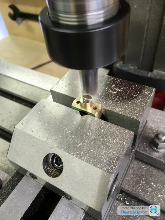
Then on to the small end. Through drilled and tapping to 5BA:
And in the same setup, drilled and reamed half way to pin size (removing the upper threads in the process):
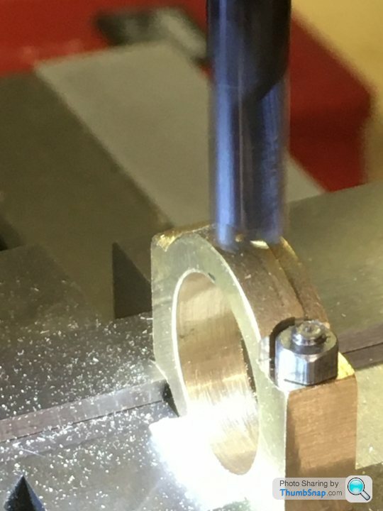
Next job was to measure and open out the forked end by milling:
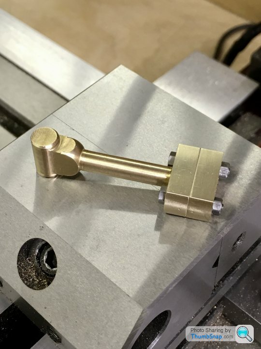
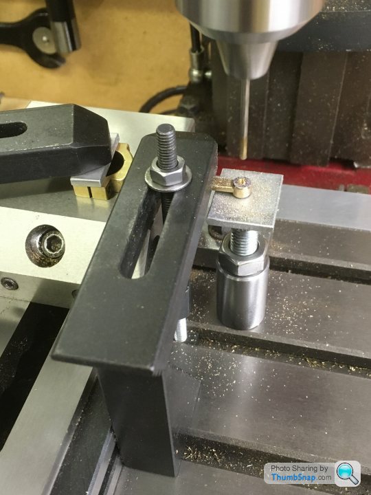
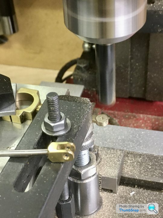
Final job was to machine the cheek bosses. I made a simple fixture out of aluminium. The end boss is a clamp and a diameter reference:

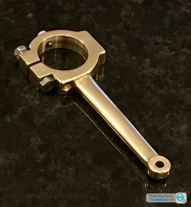
So after a quick polish, that’s another bit done:

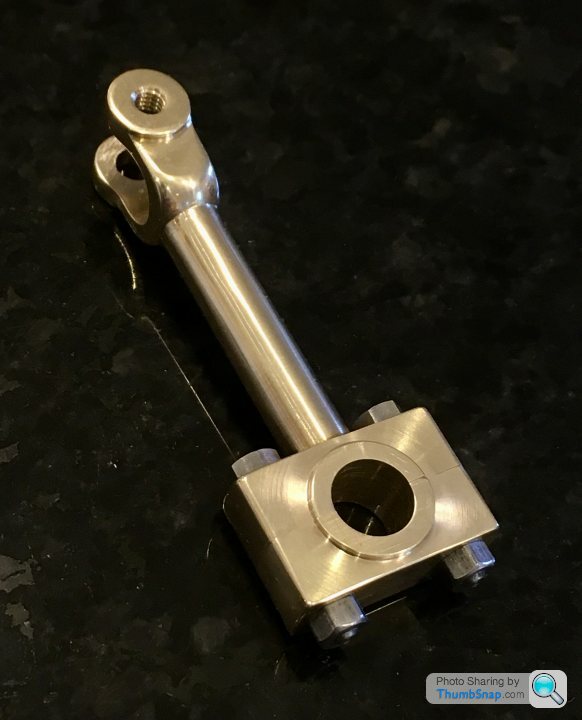

On assembly, there was a slight resistance to turning in a couple of spots, but working with a drop of light oil soon had it working smoothly with no side play at all:
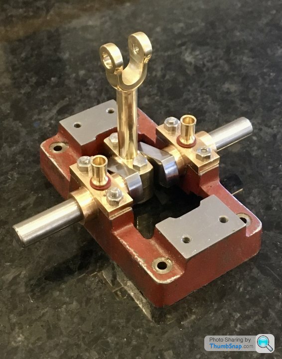
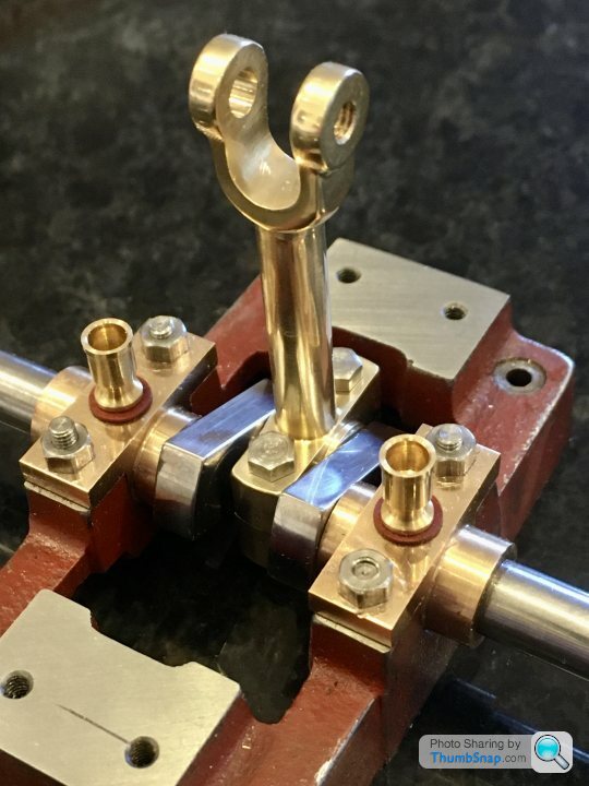
The sides of the bearing block are very close to the sole plate, but are in fact under-sized to the drawing. The slider stamping that the forked end locates around is also undersized slightly as supplied. Bit of a shame Because I could have narrowed the fork. It’s only a slight bit of play though, and I may well need it once assembled...
For some reason, it’s got a spigot on the back. I used it to locate in the mill collet, and then lowered into the vice in preparation for drilling the bolt holes. I clocked it up beforehand to check it was straight; it wasn’t bad, a few thou runout:
And again in the vice to check all the accessible surfaces were square:
I then used the edge finder to centre the spindle:
Then co-ordinate drilled the holes. I used a smaller drill than specified in order to get a tighter fit:
Then removed from the vice, marked out the split line, and the-fitted in the vice to check its level:
Then used the thin slitting saw to cut the lower block:
Then cleaned up the mating faces with an end mill:
And removed the spigot from the lower block and milled to the correct depth:
Bolted together and Loctited, the sides were milled to the right thickness to fit between the crank webs:
And the small end faces. A bit of vibration here, but I couldn’t think how else to hold it to drill bothe ends in the same setup:
Then double checked the main faces for flatness in two planes:
Then got the centre point for the crank pin hole bang on the cut line:
Drilled and reamed:
Then on to the small end. Through drilled and tapping to 5BA:
And in the same setup, drilled and reamed half way to pin size (removing the upper threads in the process):
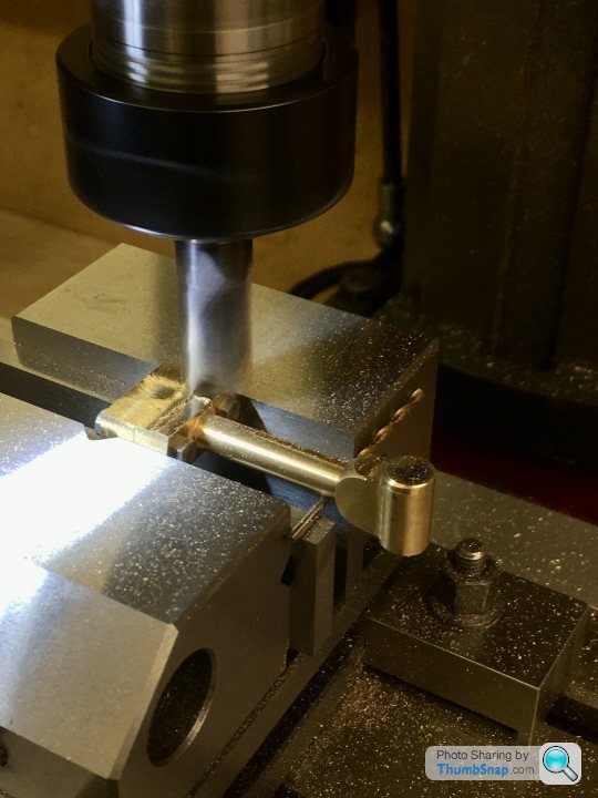
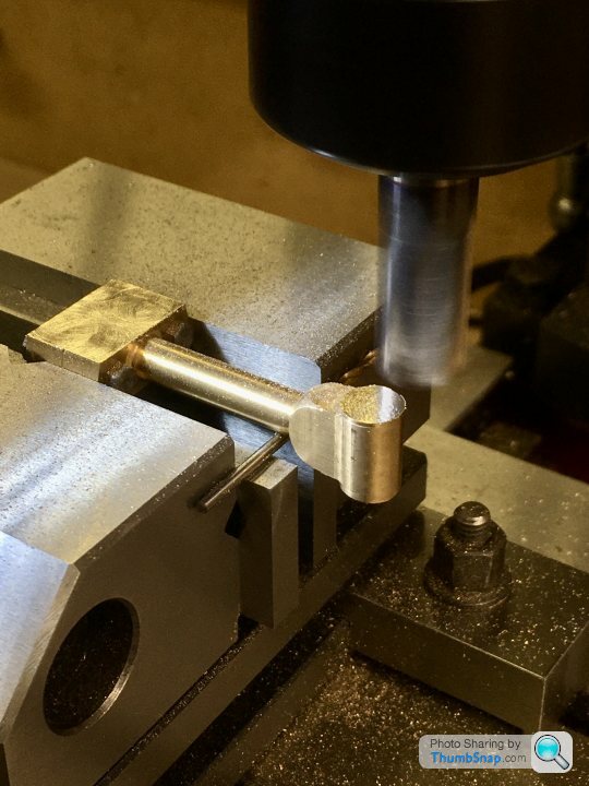
Next job was to measure and open out the forked end by milling:
Final job was to machine the cheek bosses. I made a simple fixture out of aluminium. The end boss is a clamp and a diameter reference:
So after a quick polish, that’s another bit done:
On assembly, there was a slight resistance to turning in a couple of spots, but working with a drop of light oil soon had it working smoothly with no side play at all:
The sides of the bearing block are very close to the sole plate, but are in fact under-sized to the drawing. The slider stamping that the forked end locates around is also undersized slightly as supplied. Bit of a shame Because I could have narrowed the fork. It’s only a slight bit of play though, and I may well need it once assembled...
Edited by dr_gn on Friday 18th September 21:40
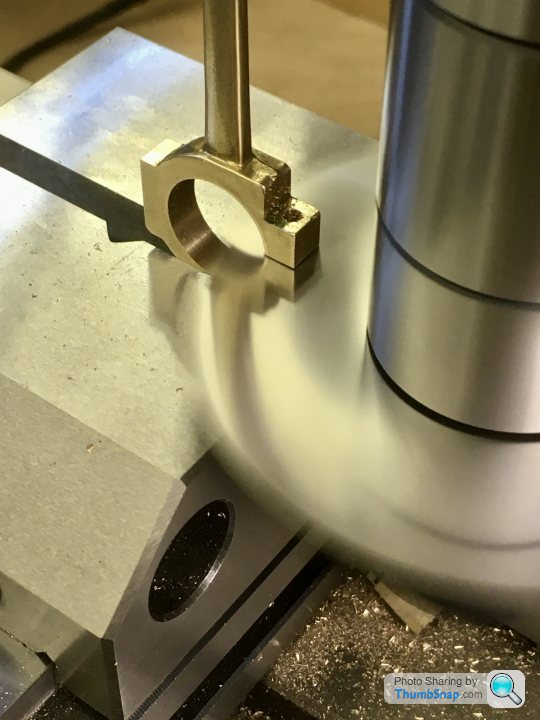
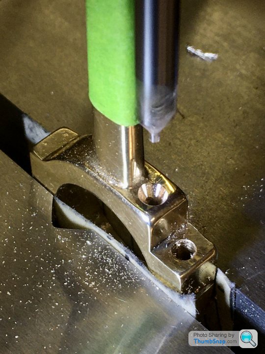
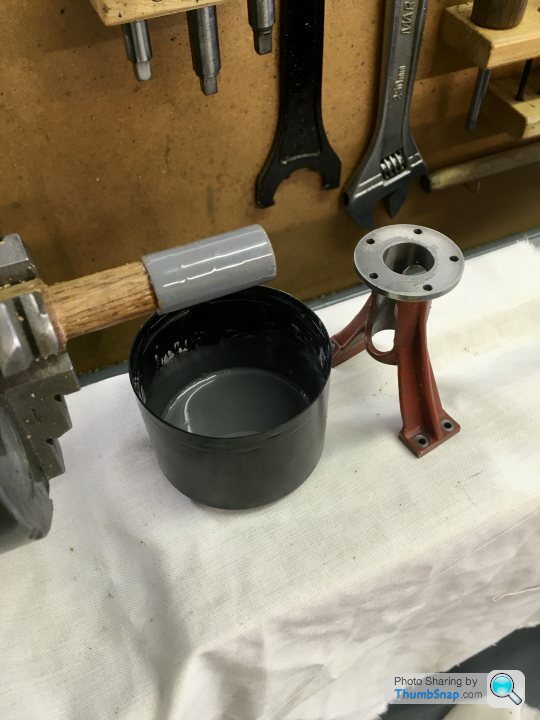
Not quite finished the eccentric strap yet - I’ve got to drill the oil hole, but can’t figure out how to do it:

There’s not enough clearance for a chuck. I was considering putting it at the other side of the stem, at 45 degrees to give myself room for the chuck, but Id like to know how to do it as per the drawing.
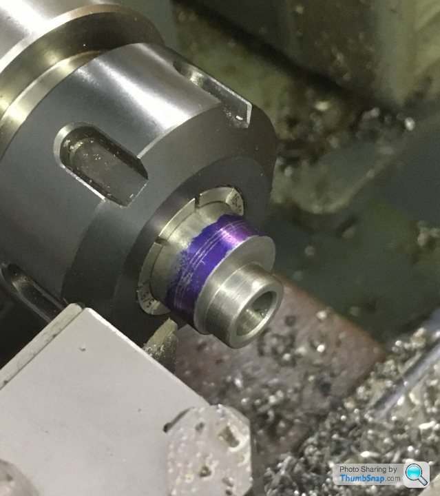
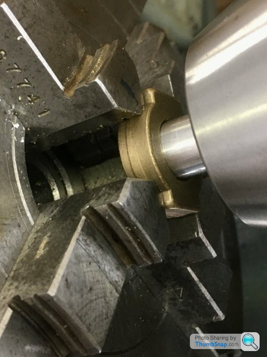
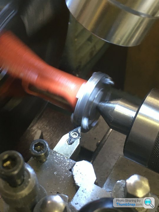
So I got on with the eccentric itself. The steel provided in the kit Is the correct o/d, so with that in mind, I faced it in the lathe:
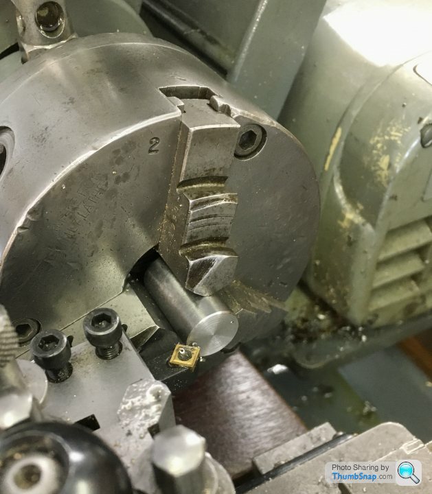
Then transferred to the mill and got the centre with the edge finder:
Then offset the x-axis by the eccentric throw, and centre drilled:

Then back to the lathe and set it in the 4-jaw chuck, centred on the offset hole:
Drilled and reamed to size:

Then turned the spigot with intermittent cuts:
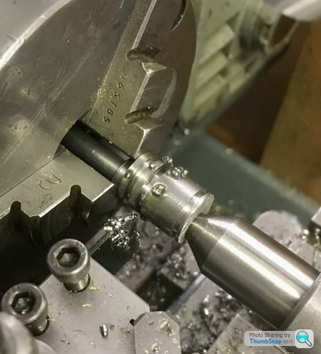
Marked out for the locating groove:
and then cut the groove with a ground down old HSS parting tool:

I started to part it off:

Then realised that because the hole is offset, it would break through at one side, and the process wouldn’t work. So I removed from the chuck and centered it on the hole again, meaning intermittent cuts for parting off:
It worked ok, but I found this material very difficult to work with . It seemed very tough, and turning tended to gouge the surface. I cleaned it up by making a wooden block and coating the face with SiC, and abraded the marks out by turning. A bit like lapping, but on the face.
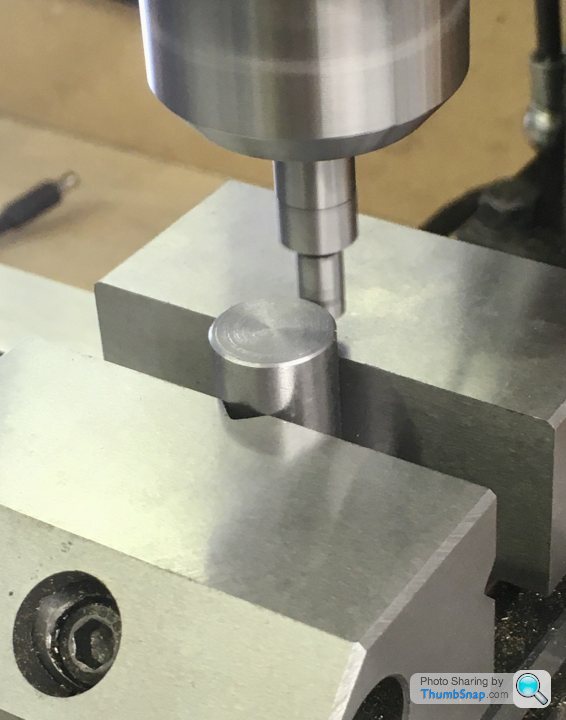
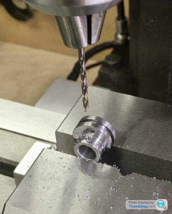
Finally, the screw hole. I set it up on the mill, getting the high point with a finger gauge:

Then drilled and tapped without any issue:
Finished, although it is a bit crunchy when rotated in the strap. No idea why.
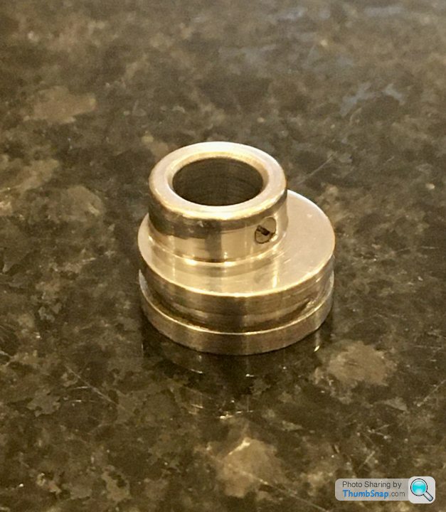

Also tidied up a few loose ends, like making an expanding mandrel and facing the main bearing external faces to length:

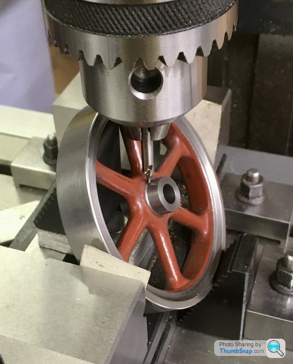
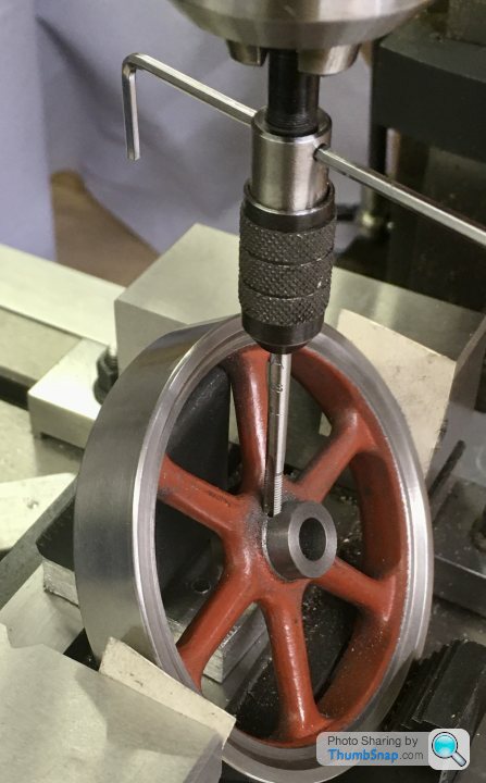
Again using the mandrel, facing the flywheel bosses to length, then mounting on the mill and drilling and tapping the screw hole:
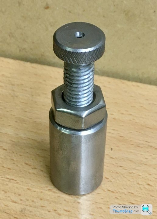
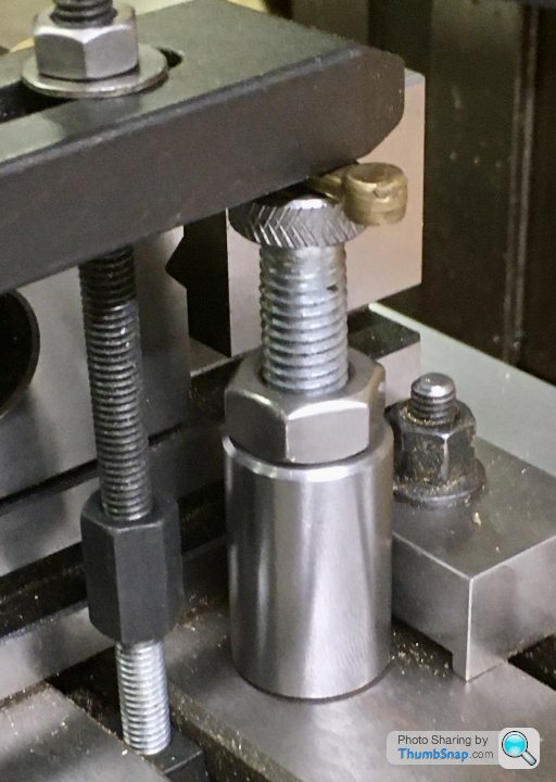
And finally, machining the eccentric strap stepped locating bolt:

Not the best fit in the groove -a bit loose - but I found it difficult to get it right. Might have another go at that sometime.
There’s not enough clearance for a chuck. I was considering putting it at the other side of the stem, at 45 degrees to give myself room for the chuck, but Id like to know how to do it as per the drawing.
So I got on with the eccentric itself. The steel provided in the kit Is the correct o/d, so with that in mind, I faced it in the lathe:
Then transferred to the mill and got the centre with the edge finder:
Then offset the x-axis by the eccentric throw, and centre drilled:
Then back to the lathe and set it in the 4-jaw chuck, centred on the offset hole:
Drilled and reamed to size:
Then turned the spigot with intermittent cuts:
Marked out for the locating groove:
and then cut the groove with a ground down old HSS parting tool:
I started to part it off:
Then realised that because the hole is offset, it would break through at one side, and the process wouldn’t work. So I removed from the chuck and centered it on the hole again, meaning intermittent cuts for parting off:
It worked ok, but I found this material very difficult to work with . It seemed very tough, and turning tended to gouge the surface. I cleaned it up by making a wooden block and coating the face with SiC, and abraded the marks out by turning. A bit like lapping, but on the face.
Finally, the screw hole. I set it up on the mill, getting the high point with a finger gauge:
Then drilled and tapped without any issue:
Finished, although it is a bit crunchy when rotated in the strap. No idea why.
Also tidied up a few loose ends, like making an expanding mandrel and facing the main bearing external faces to length:
Again using the mandrel, facing the flywheel bosses to length, then mounting on the mill and drilling and tapping the screw hole:
And finally, machining the eccentric strap stepped locating bolt:
Not the best fit in the groove -a bit loose - but I found it difficult to get it right. Might have another go at that sometime.
rolster said:
I noticed your excentric strap issues, but not sure how far you have already gone into the machining process, as ideally before the top surface of the excentric strap on the bolted side is reduced down, then you: clamp the strap vertically; file a small flat (but within what you will take away later on finishing) and center punch the hole centre, by hand. Then carefully using a long drill bit (to get the chuck above the top of the excentric strap), drill the hole vertically down. If you don't have a long drill set, then an extension with a collar can be made just make the hole in the end to hold the drill bit an interfearance fit, heat the collar sligthy and pop the drill bit in the freezer, then insert the drill bit and let them normalise. You can then heat the collar afterwards to retrieve the drill bit. Alternatively use the same drill to drill a hole in the extension and then loctight it in place, but then you loose the drill bit. As seen there is not enough room for a centre drill, unless you can find some of the long ones, which i have not seen for a very long time. For the conical part of the oil resevoir, i suggest a taper reamer and then hand finishing the flare with a small burr or such. Very much enjoying the project and your updates.
Thanks rolster. On the advice of the ME forum, I managed to find a long series (3” long) 4mm O/D centre drill, which will just fit next to the arm, drill the hole and make the countersink in one operation.ETA, I've finished the strap apart from the hole. The part is supplied as a brass stamping, and is near net shape. A few flats need milling, and of course the flanks and holes, but the area where the oil hole is just needs polishing, so you get one change to center it correctly. Shouldn't be an issue with the edge finder though. Cheers.
Edited by dr_gn on Monday 28th September 11:27
rolster said:
Great news on finding the long centre drill. I have not seen one in a long time, they are so useful but usually break when machining sticky materials. i think the last time i saw any, was when digging through some trays at Tracy Tools, when they used to be in Dartmouth. I have a vague memory of the excentric strap being a casting way back when, but obviously now a stamping.
It looks like a casting to me, as did the connecting rod and the cross-slide, but they are often referred to as stampings, so I don't really know.Today I re-visited the cylinder, and made some progress with the steam ports.
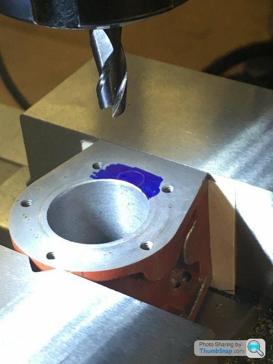
First off, the pockets adjacent to the cylinder. A depth and diameter is given, but no centre location. I used a 6mm milling cutter, moved to marked-out arcs defined by the gasket cut-outs:
Then the exhaust drilling, to measured dimensions from the drawing. I marked out the projected position of the cast-in ports as a double check. Luckily the drill broke through the back of the port perfectly:
Then opened up the hole for a few mm, and tapped for the exhaust pipe fitting:

So that one turned out ok:


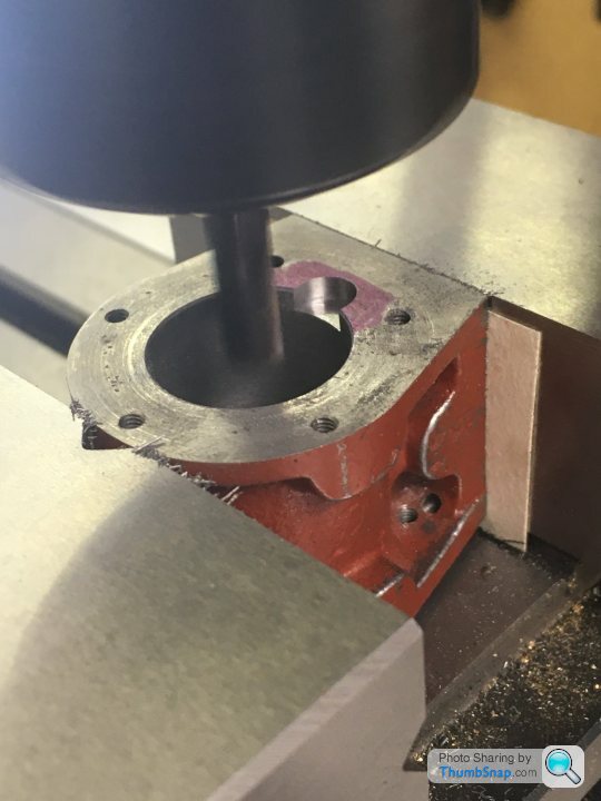
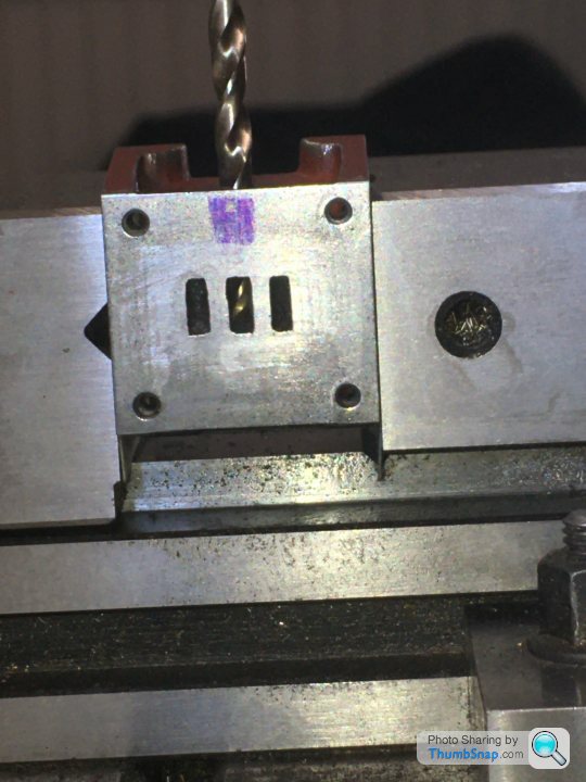
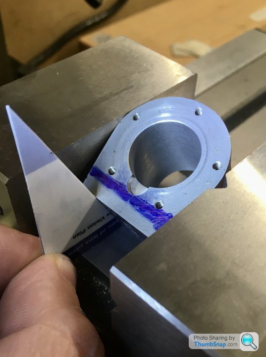
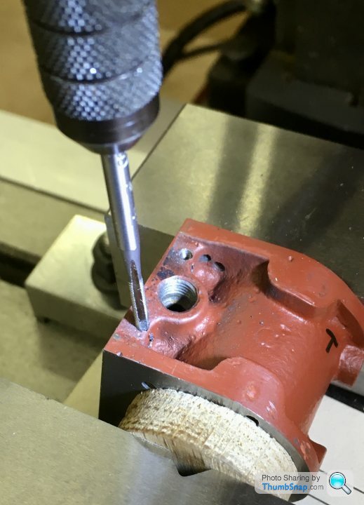
Then the tricky angled ones I’ve been putting off for a while. I started by extending all the port lines to the edge of the casting, and effectively drawing the positions of the ports on the side using the projected lines and measured depths. I then got the tilt angle using a protractor, and made a setting jig from an old plastic card (26 degrees):
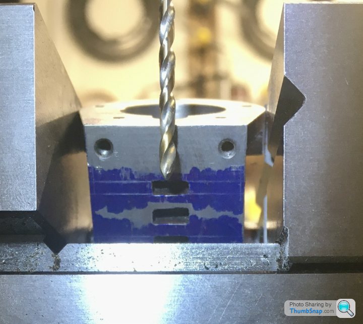
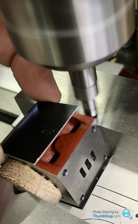
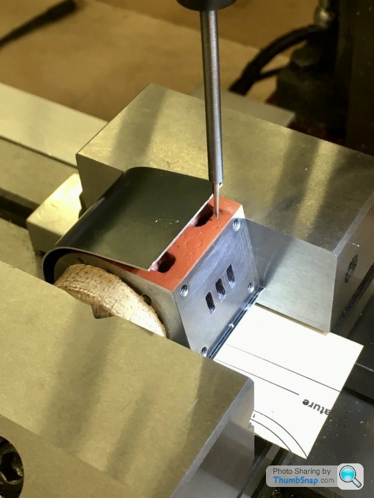
The machined port face was located against the gap in the vice bed, ensuring it was square. Then a centre drill was used to start the hole dead in the corner of the milled port:
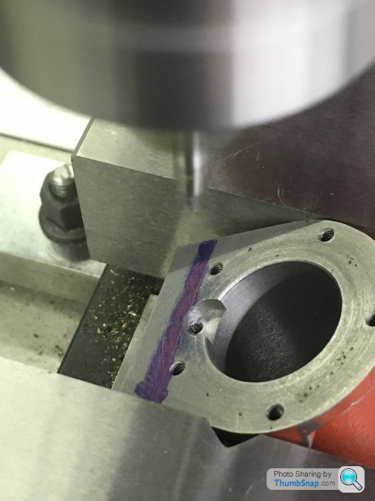
With the dro zeroed, I moved the casting so I could set the z-stop such that any error wouldn’t result in breaking into the exhaust port, giving me a chance to correct things if necessary:
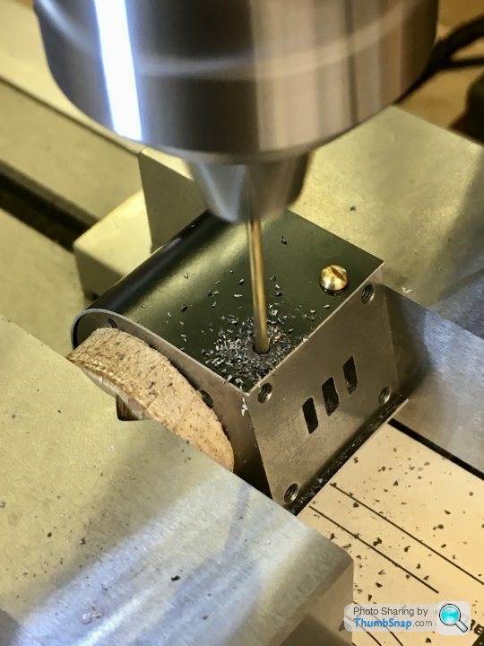
Then moved back to x-zero and drilled. It broke through bang in the corner of the port, as did the other side. Which was nice:

Next will be the insulation jacket securing holes, and the drain cock holes, but I’m waiting for a tap for those.
First off, the pockets adjacent to the cylinder. A depth and diameter is given, but no centre location. I used a 6mm milling cutter, moved to marked-out arcs defined by the gasket cut-outs:
Then the exhaust drilling, to measured dimensions from the drawing. I marked out the projected position of the cast-in ports as a double check. Luckily the drill broke through the back of the port perfectly:
Then opened up the hole for a few mm, and tapped for the exhaust pipe fitting:
So that one turned out ok:
Then the tricky angled ones I’ve been putting off for a while. I started by extending all the port lines to the edge of the casting, and effectively drawing the positions of the ports on the side using the projected lines and measured depths. I then got the tilt angle using a protractor, and made a setting jig from an old plastic card (26 degrees):
The machined port face was located against the gap in the vice bed, ensuring it was square. Then a centre drill was used to start the hole dead in the corner of the milled port:
With the dro zeroed, I moved the casting so I could set the z-stop such that any error wouldn’t result in breaking into the exhaust port, giving me a chance to correct things if necessary:
Then moved back to x-zero and drilled. It broke through bang in the corner of the port, as did the other side. Which was nice:
Next will be the insulation jacket securing holes, and the drain cock holes, but I’m waiting for a tap for those.
dhutch said:
Great as always, always a bit of a 'hope this works out ok' as you set off drilling that sort of a hole.
Not done it in this sort of setting, but have drilled a few holes through walls in houses and hoped the exit point it about where planned!
Yes exactly. I remember when I was a kid, my dad and I wanted to put a phone in the separate garage next door, so we drilled a hole for the extension cable under the soffit of their bungalow, thinking it was above the level of the living room ceiling, and would end up in the loft. It didn't. My mum wasn't happy when a ragged exit hole suddenly appeared in the middle of the wall opposite where she was sitting...Much shouting.Not done it in this sort of setting, but have drilled a few holes through walls in houses and hoped the exit point it about where planned!
Happy days.
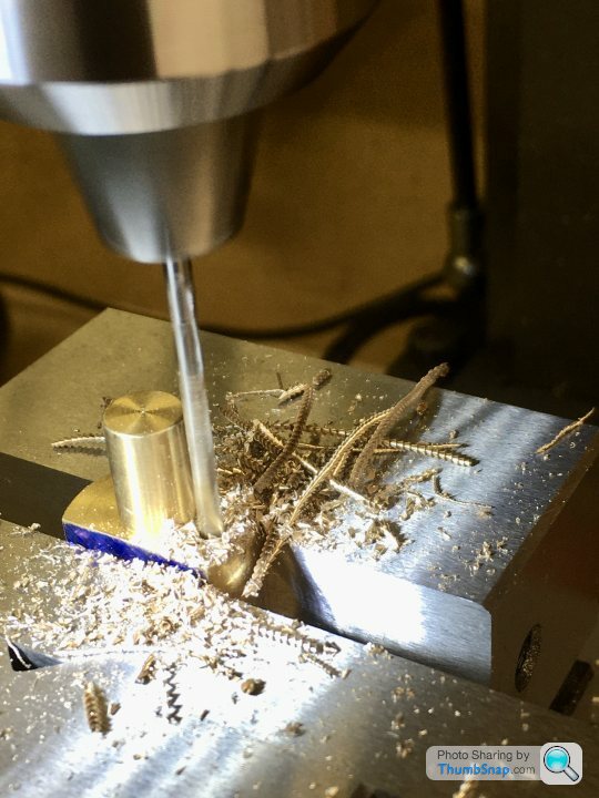
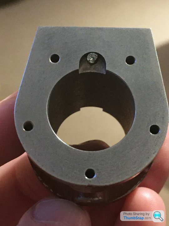
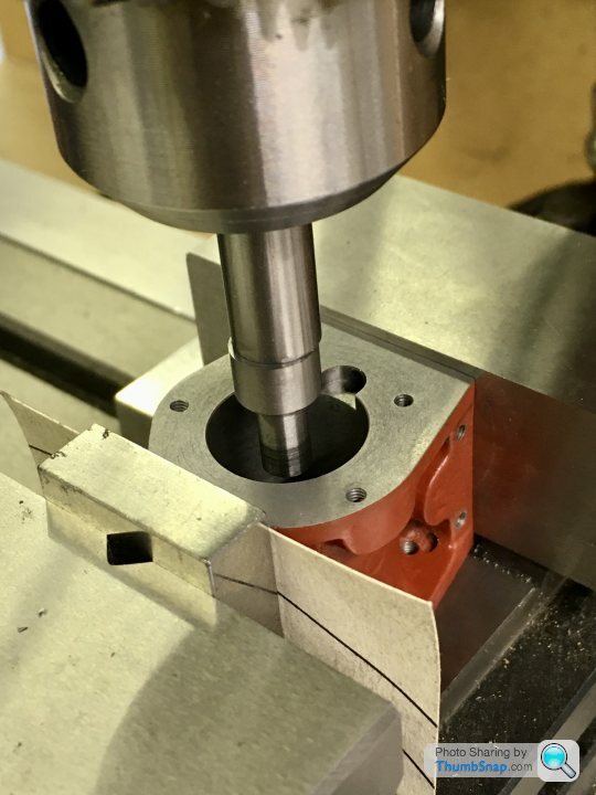
So today I tried to mill the outer cylinder concentric with the upper cylinder, using a method suggested on the forum. This involved positioning a rod in the bore, putting it in the vice and milling a series of flats all around:

I must admit I found it hard to position correctly - it was easy to get it into a position where the o/d wasn’t at its lowest point relative to the cutter. This culminated in it grabbing, and damaging the casting:

Maybe it wasn’t orientated right, and I guess the vice should have been tighter, but either way it’s not a process I was particularly happy with.
Anyway, luckily the damage was only cosmetic, and some epoxy metal and flatting and re-priming (for the next stages of marking out) resulted in the desired outcome, ie a consistent step to the end caps:


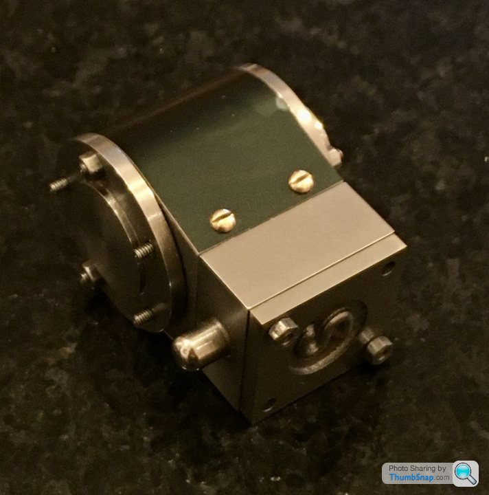
I profiled the cladding using an 18mm socket, and test fitted it. It still needs trimming a bit:
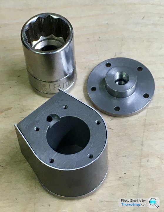
But so far, so good:
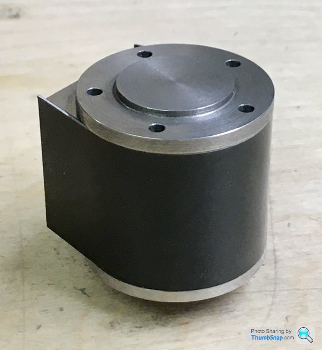
Not sure if the cladding is some kind of anodised metal, but the finish is slightly flawed at one point. I might spray it satin black in the end.
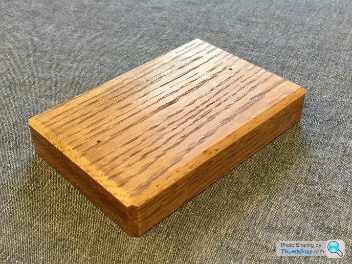
Also painted the box bed and screwed it to the wooden base:

I must admit I found it hard to position correctly - it was easy to get it into a position where the o/d wasn’t at its lowest point relative to the cutter. This culminated in it grabbing, and damaging the casting:
Maybe it wasn’t orientated right, and I guess the vice should have been tighter, but either way it’s not a process I was particularly happy with.
Anyway, luckily the damage was only cosmetic, and some epoxy metal and flatting and re-priming (for the next stages of marking out) resulted in the desired outcome, ie a consistent step to the end caps:
I profiled the cladding using an 18mm socket, and test fitted it. It still needs trimming a bit:
But so far, so good:
Not sure if the cladding is some kind of anodised metal, but the finish is slightly flawed at one point. I might spray it satin black in the end.
Also painted the box bed and screwed it to the wooden base:
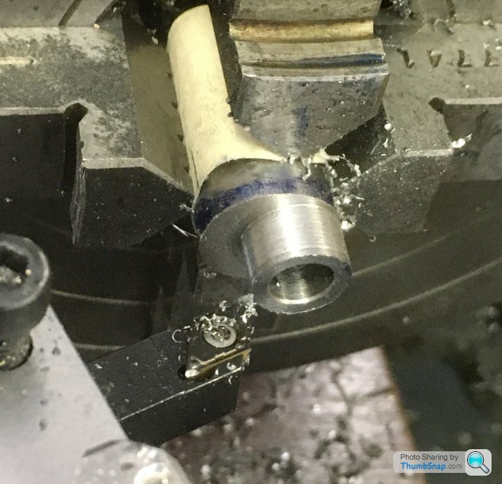
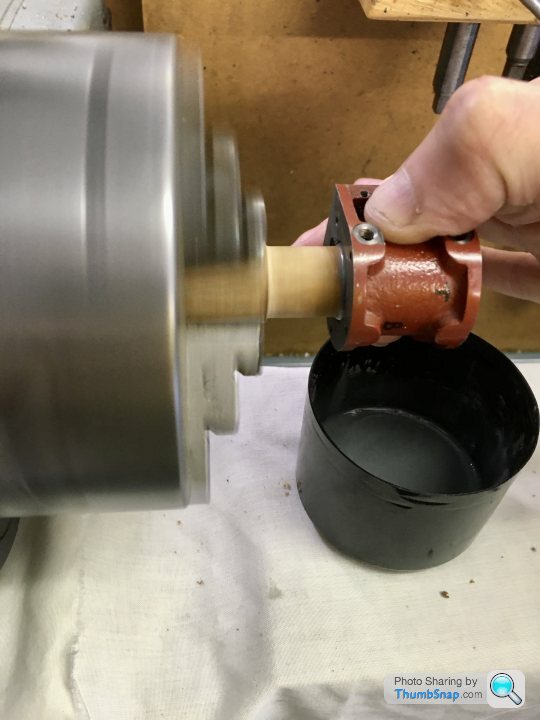
Eccentric strap. Started by mounting the stamping into the 4-jaw chuck, using a tight fitting spigot in the tailstock chuck as a guide:
Then bored the hole:

Transferred to the mill and faced the main bore sides with the fly cutter:
The shaft was bent:

So I straightened it the best I could using a screwdriver and spanner as levers:

Then milled the flats and corners level:

and drilled the clamp hole:
and then the tapped locating pin hole after first milling a bit of a flat:
Cut the slot using the 0.8 mm slitting saw:
Then drilled the small end for its bolt. The specified clearance hole sizes on the plans are all way too big for a good fit:
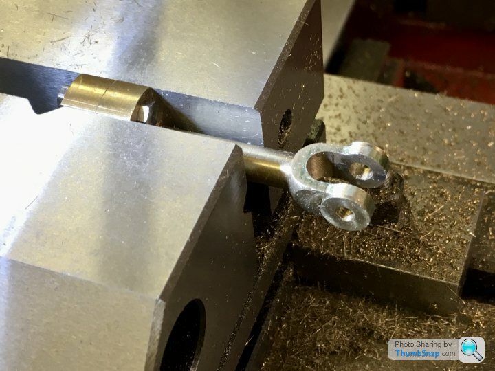
and milled the faces symmetrical and to be a sliding fit in the fork end of the valve rod:
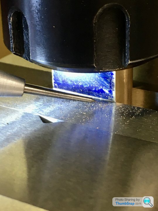
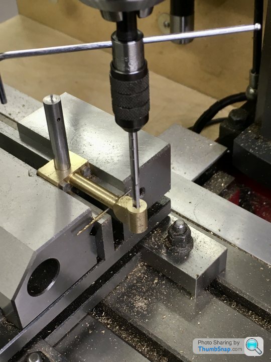
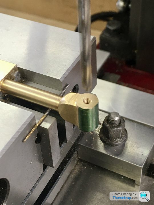
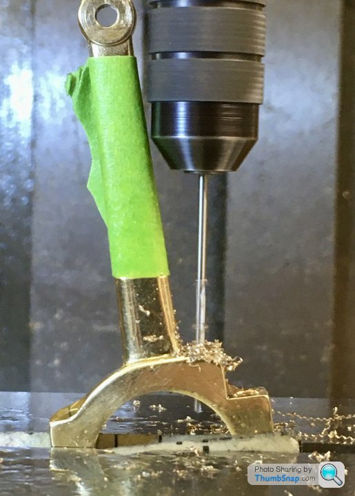
Finally the oil hole. Tricky one because the 1mm/4mm long series centre drill would have removed way too much material had I used it to drill through to the bore. I decided to make a cranked oil hole by first angling the rod to give clearance for a 1mm standard drill in a small chuck, and making a centre dot with the long centre drill:

Then drilling to the bore using a 1mm drill:
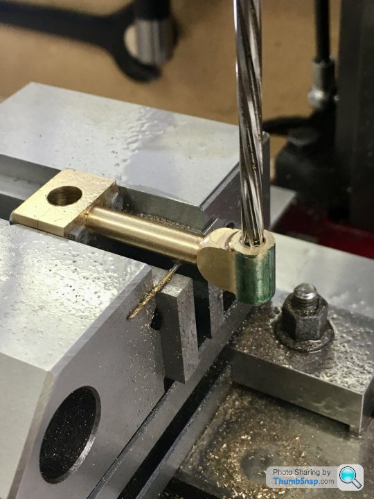
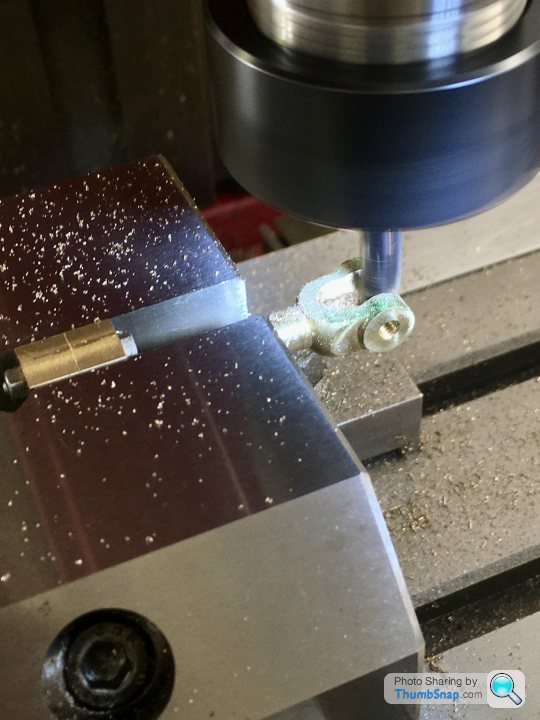
Then returning to vertical and using the center drill to get a chamfer on the flat surface, while allowing the 1mm part to break into the initial hole:
Made a bit of a meal of it I guess, but there was no room available for a simpler method (that I could think of), and I wanted an un-skewed cone at the surface:
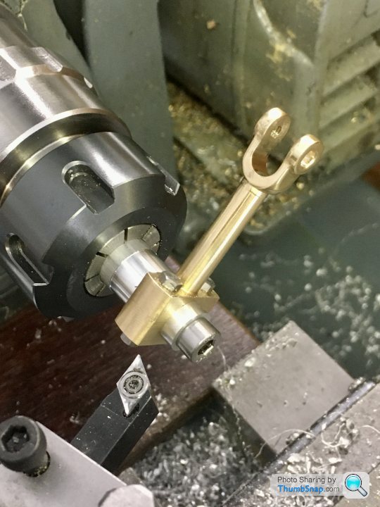
I also turned two standard nuts to thin nuts to make them look less clunky:

Here it is test fitted to the eccentric. I cut the eccentric screw down by threading it into some thin strip and filing the end off:

Getting there.
Then bored the hole:
Transferred to the mill and faced the main bore sides with the fly cutter:
The shaft was bent:
So I straightened it the best I could using a screwdriver and spanner as levers:
Then milled the flats and corners level:
and drilled the clamp hole:
and then the tapped locating pin hole after first milling a bit of a flat:
Cut the slot using the 0.8 mm slitting saw:
Then drilled the small end for its bolt. The specified clearance hole sizes on the plans are all way too big for a good fit:
and milled the faces symmetrical and to be a sliding fit in the fork end of the valve rod:
Finally the oil hole. Tricky one because the 1mm/4mm long series centre drill would have removed way too much material had I used it to drill through to the bore. I decided to make a cranked oil hole by first angling the rod to give clearance for a 1mm standard drill in a small chuck, and making a centre dot with the long centre drill:
Then drilling to the bore using a 1mm drill:
Then returning to vertical and using the center drill to get a chamfer on the flat surface, while allowing the 1mm part to break into the initial hole:
Made a bit of a meal of it I guess, but there was no room available for a simpler method (that I could think of), and I wanted an un-skewed cone at the surface:
I also turned two standard nuts to thin nuts to make them look less clunky:
Here it is test fitted to the eccentric. I cut the eccentric screw down by threading it into some thin strip and filing the end off:
Getting there.
Also been fiddling about finishing some other stuff. The lower cylinder boss didn’t match the standard diameter, so secured them together and turned as a pair (should have done that in the first place):

Also needed 0.6mm taking off the height:

I took it off the feet because the cross slide bore was machined in the same setup as the top surface.
Also needed 0.6mm taking off the height:
I took it off the feet because the cross slide bore was machined in the same setup as the top surface.
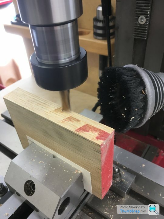
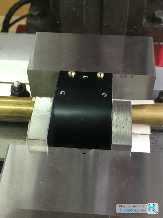
Back to the cylinder and it’s aluminium shroud. I Bent it to a good fit, but still oversized. The challenge being to drill holes for the 4 retaining screws, exhaust pipe and drain cocks. After much thought I settled on this:
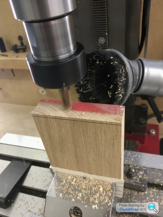
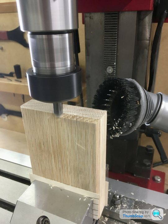
Align the cylinder side in the vice, using a turned hardwood plug as a spacer. This allows the vice to be tightened without crushing the excess aluminium:
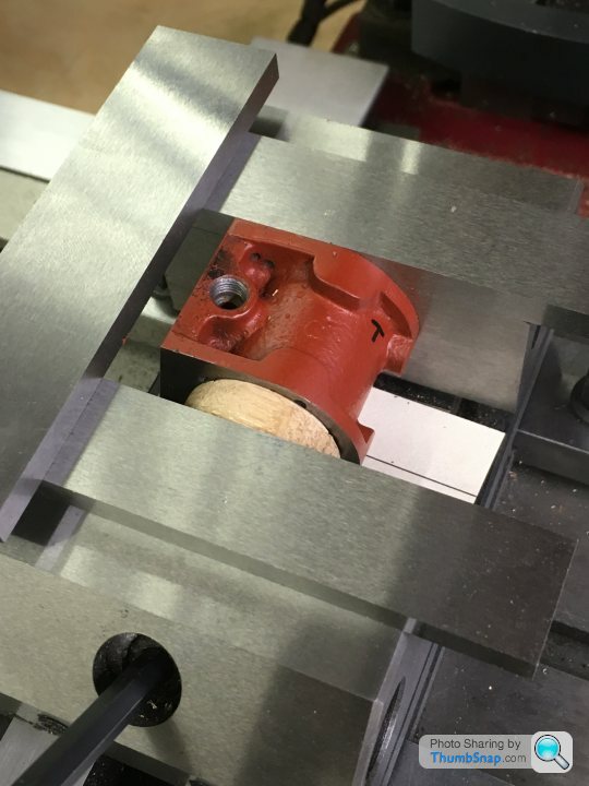
After measuring and getting co-ordinates for both retaining screws, Spring the shroud in place and hold tight by hand, then drill a pilot hole:
Remove shroud, drill and tap 8BA. I opened the shroud holes up a bit by hand. The hole is literally right on the edge of being sound - it’s actually broken through the wall towards its base:
Re-fit shroud, screw in place and repeat for the other hole:
Then turn around and repeat on the other side. I used an edge finder and a wiggled point to determine datums and co-ordinates again:

That worked fine:

Then it was a simple matter of flatting the excess aluminium on the surface plate:

The screws can’t be tightened without bowing the shroud - it’s un-supported where the screws are. I might put some epoxy metal behind and file it flush at some point, unless anyone can suggest a better method.


I’m quite pleased with the fit - especially next to the valve chest. I’m glad I thought to make the sides wider than specified on the drawing to make everything flush.
Align the cylinder side in the vice, using a turned hardwood plug as a spacer. This allows the vice to be tightened without crushing the excess aluminium:
After measuring and getting co-ordinates for both retaining screws, Spring the shroud in place and hold tight by hand, then drill a pilot hole:
Remove shroud, drill and tap 8BA. I opened the shroud holes up a bit by hand. The hole is literally right on the edge of being sound - it’s actually broken through the wall towards its base:
Re-fit shroud, screw in place and repeat for the other hole:
Then turn around and repeat on the other side. I used an edge finder and a wiggled point to determine datums and co-ordinates again:
That worked fine:
Then it was a simple matter of flatting the excess aluminium on the surface plate:
The screws can’t be tightened without bowing the shroud - it’s un-supported where the screws are. I might put some epoxy metal behind and file it flush at some point, unless anyone can suggest a better method.
I’m quite pleased with the fit - especially next to the valve chest. I’m glad I thought to make the sides wider than specified on the drawing to make everything flush.
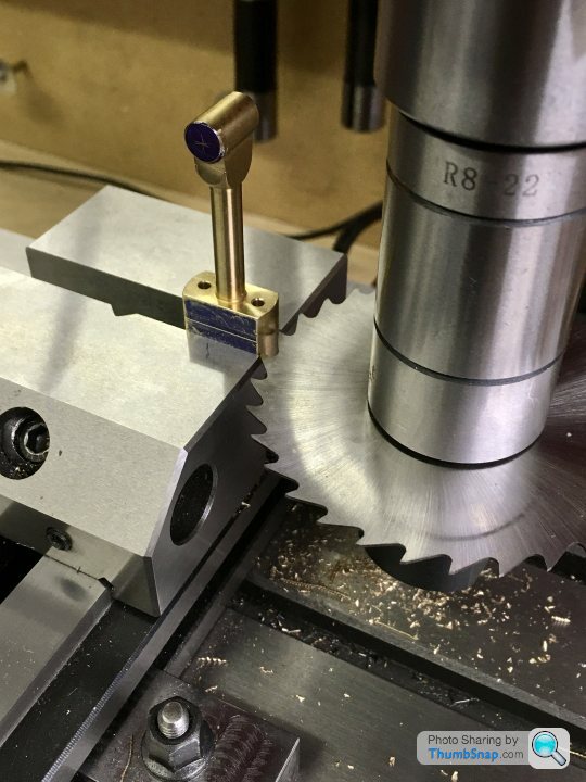
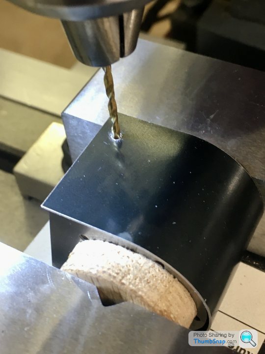
Then the drain cock holes. These will be clearance holes in the shroud, drilled and tapped in the cylinder casting. The issue now was to drill pilot holes without crushing the shroud. I opted to first get the centre of the cylinder with the casing held vertically in the vice. The fixed jaw bring the y-datum:
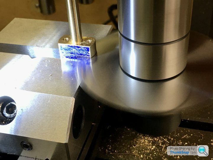
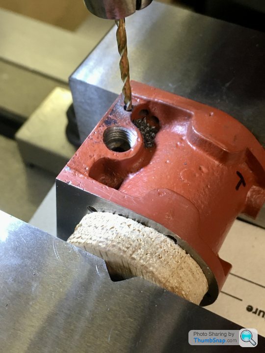
Then turn through 90 degrees. The y centre distance is now the y-axis offset from the fixed jaw. I then spot- faced the casting with a 6.5mm slot drill, after using the edge finder to determine the x-offset:

The second spot-face caused the drill to grab, and damage the casting. I have a theory about what is causing this recurrent issue with the z-axis:

Anyway, I re-set in the vice and centre marked the spot faces:

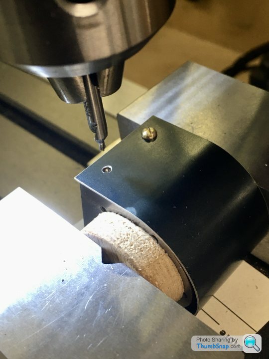
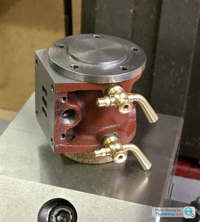
Then fitted the shroud and clamped in the vice using a stiff brass rod, offset from the vice jaw with some old 1” slip gauges to avoid contact with the moving jaw:

Then centre drilled using identical co-ordinates:

Then drilled 1mm diameter straight into the bore:

Then drilled and tapped to the drain cock thread size and depth.
Next on to the exhaust hole in the shroud using the same basic method:

The drain cock and exhaust holes need opening up - I’ve got a small step drill on order. Also need some fibre washers to seat the drain cock bosses:

Overall OK so far, but the anodising is so thin and easily scratched that I may end up painting it.

I also need to sort out the issue with the mill z-feed before it causes a scrap casting.
Then turn through 90 degrees. The y centre distance is now the y-axis offset from the fixed jaw. I then spot- faced the casting with a 6.5mm slot drill, after using the edge finder to determine the x-offset:
The second spot-face caused the drill to grab, and damage the casting. I have a theory about what is causing this recurrent issue with the z-axis:
Anyway, I re-set in the vice and centre marked the spot faces:
Then fitted the shroud and clamped in the vice using a stiff brass rod, offset from the vice jaw with some old 1” slip gauges to avoid contact with the moving jaw:
Then centre drilled using identical co-ordinates:
Then drilled 1mm diameter straight into the bore:
Then drilled and tapped to the drain cock thread size and depth.
Next on to the exhaust hole in the shroud using the same basic method:
The drain cock and exhaust holes need opening up - I’ve got a small step drill on order. Also need some fibre washers to seat the drain cock bosses:
Overall OK so far, but the anodising is so thin and easily scratched that I may end up painting it.
I also need to sort out the issue with the mill z-feed before it causes a scrap casting.
vanwithwindows said:
Absolutely love this! Was given a small lathe and milling machine probably 10 years ago and managed to figure out enough to build a stirling engine.
Really want to recommision them and build something else now...
Go for it. I’ve never attempted anything like this before, but I’m loving everything from modding the machine tools to figuring out machining & fixturing strategies. Plus I should have something decent looking to fiddle about with at the end of it.Really want to recommision them and build something else now...
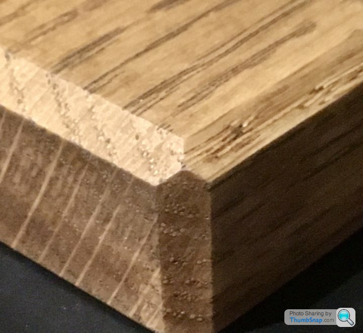
So the final bits of machining I think - the piston and cross head. Before turning them to size, I made a couple of laps out of turned down oak:

Charged them with #600 SiC and oil, and worked the bores up and down:

I think the laps should have been a bit tighter - they quickly became quite free in the bores, but anyway, onwards...

Charged them with #600 SiC and oil, and worked the bores up and down:
I think the laps should have been a bit tighter - they quickly became quite free in the bores, but anyway, onwards...
Started by facing the brass for the cylinder:

Drilling and tapping to 5BA:

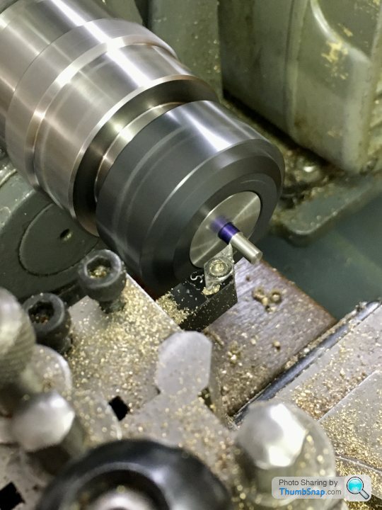
Then marking out and turning the oil grooves:
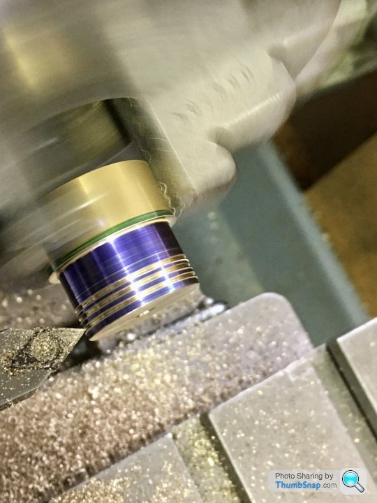
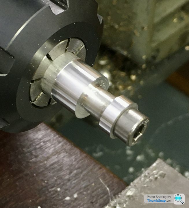
Then turned to finished diameter +0.5mm, and parted off.
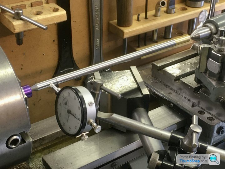
Next, after confirming the piston rod ran true in the collet chuck (it was within 0.002”), faced it off, turned down and ran a 5BA thread down, to the depth of the piston:

Then tightened the piston onto it, faced the assembly, and scribed a line over the exposed join so it can always be tightened to the same position:

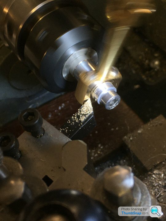
Then turned to he O/D in fractions of a mm until it just fitted in the cylinder bore:

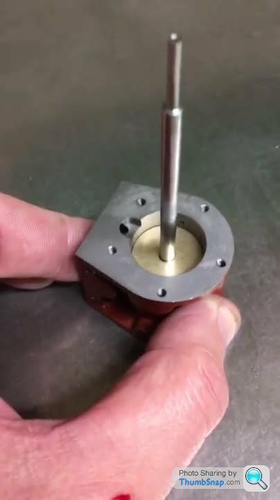
It’s a good fit; if I put the cylinder vertically on the surface plate and cover the valve port and drain hole up, the piston slowly makes its way down the bore. I don’t think it needs lapping. The piston and rod is also a nice sliding fit With the lower cover fitted:
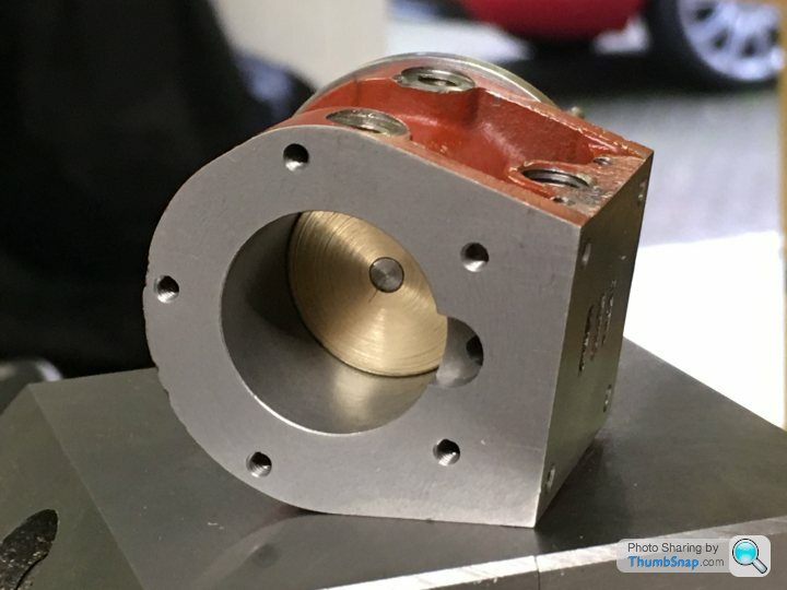
Here’s a video that should work if you click on it:
Now to repeat the process for the cross head end of the piston rod.
Drilling and tapping to 5BA:
Then marking out and turning the oil grooves:
Then turned to finished diameter +0.5mm, and parted off.
Next, after confirming the piston rod ran true in the collet chuck (it was within 0.002”), faced it off, turned down and ran a 5BA thread down, to the depth of the piston:
Then tightened the piston onto it, faced the assembly, and scribed a line over the exposed join so it can always be tightened to the same position:
Then turned to he O/D in fractions of a mm until it just fitted in the cylinder bore:
It’s a good fit; if I put the cylinder vertically on the surface plate and cover the valve port and drain hole up, the piston slowly makes its way down the bore. I don’t think it needs lapping. The piston and rod is also a nice sliding fit With the lower cover fitted:
Here’s a video that should work if you click on it:
Now to repeat the process for the cross head end of the piston rod.
Edited by dr_gn on Sunday 4th October 19:30
dhutch said:
That video is lovely!
Also; you appear to have a hole in the back of your thumb.
Daniel
Thanks!Also; you appear to have a hole in the back of your thumb.
Daniel
Yes I noticed the hole. If I’m ever threading manually in the lathe, or reaching for something near the mill head, I seem to end up with a cut. That insert for cutting stainless, with the knife edges and small tip radius is particularly harsh.
Tango13 said:
dr_gn said:
Then transferred to the mill and got the centre with the edge finder:
Why on earth are you using a round edge finder to try to find a datum on a round part?You have a perfectly straight vice jaw to use the edge finder on instead of hoping the edge finder is on centre with the round part.
Or just buy one of these...
https://www.machine-dro.co.uk/dial-co-axial-center...
Takes far longer to describe than to do.
The moving vice jaw doesn’t necessarily move perfectly parallel to the fixed one when clamping a Non-parallel part, so I’d potentially be measuring a non-symmetrical taper and therefore getting a false centre.
Why on earth would I spend all that money on an elaborate tool when I can do the same thing perfectly well with what I’ve already got?
Gassing Station | Scale Models | Top of Page | What's New | My Stuff