Stuart 10V Vertical Steam Engine
Discussion


fourfoldroot said:
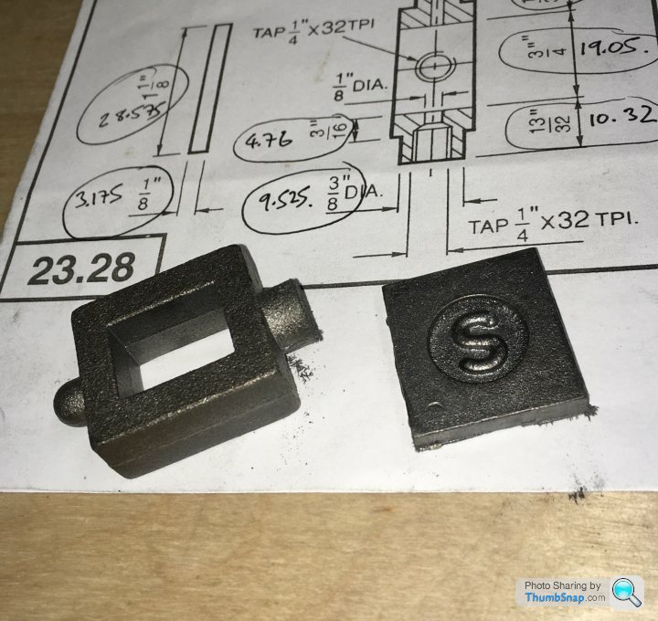
I think the brass slider/valve is a pressing rather than a casting, so much cleaner finish. As you say,all you need to do is flat the face. You may need to fettle the prongs where the valve rod block slots in. But nothing machiney.
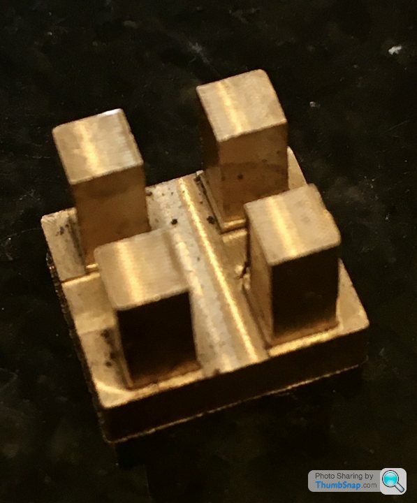
Mine’s fully machined. Maybe they ran out of forgings?Had a spare hour and a half, so started on the valve chest, while the dimensions of the cylinder port face and lagging were still fresh in my mind:
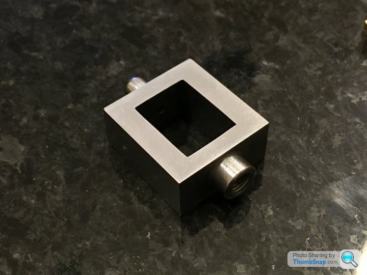
I tried the approach of cleaning up the outer surfaces, measuring, and re-cutting to size using the DROs, and with scribed lines as a sanity check:
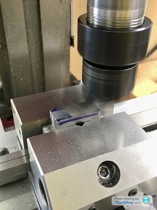

All faces were square and dimensions were spot-on to the limit of what I can measure, so that’s one method I can hopefully use from now on:
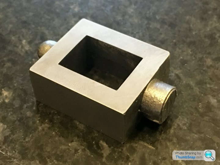
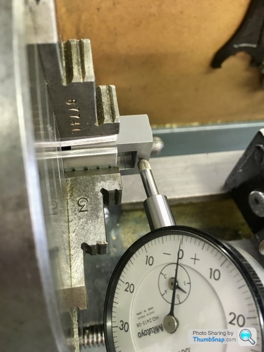
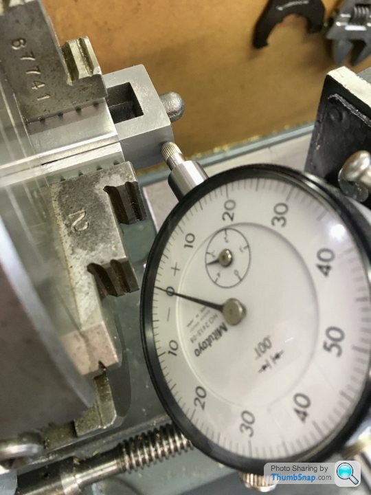
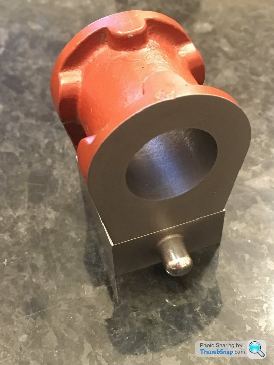
However, this still leaves the bosses to machine. I need to turn these in the 4 jaw chuck, but I couldn’t think how to centralise them accurately. The cast bosses may not now be in the exact mid point of their faces, but they need to be. Anyway I’m going to try this centering ring I made from some scrap brass:

It’s a tight fit over the edges of the chest, and I’ll fit it over the 10mm or so of the part protruding from the jaws. The back face of the ring will butt up to them. If I can center the part using a DTI on the ring, the excess material removed from the bosses should leave me with the finished drilled, tapped and reamed features bang in the middle, and the chuck jaws should ensure they are central within the box:
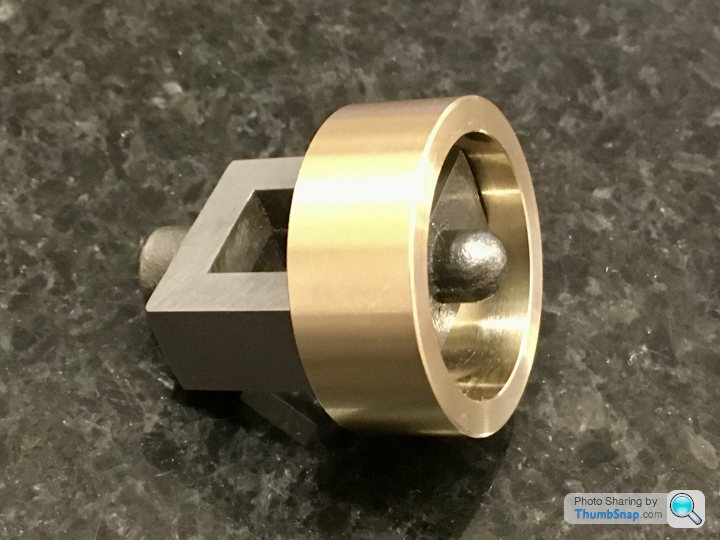
That’s the theory anyway.
I tried the approach of cleaning up the outer surfaces, measuring, and re-cutting to size using the DROs, and with scribed lines as a sanity check:
All faces were square and dimensions were spot-on to the limit of what I can measure, so that’s one method I can hopefully use from now on:
However, this still leaves the bosses to machine. I need to turn these in the 4 jaw chuck, but I couldn’t think how to centralise them accurately. The cast bosses may not now be in the exact mid point of their faces, but they need to be. Anyway I’m going to try this centering ring I made from some scrap brass:
It’s a tight fit over the edges of the chest, and I’ll fit it over the 10mm or so of the part protruding from the jaws. The back face of the ring will butt up to them. If I can center the part using a DTI on the ring, the excess material removed from the bosses should leave me with the finished drilled, tapped and reamed features bang in the middle, and the chuck jaws should ensure they are central within the box:
That’s the theory anyway.
Edited by dr_gn on Monday 15th June 22:20
fourfoldroot said:
This is where you find out if the castings have any chilled patches. They will show up as very shiny hard spots when cutting and very quickly wreck the milling cutters. I had quite a few spots on my stuart kit. If you have a log burner, put them in a good hot fire and leave them to cool overnight,they should be easily machinable by morning. First time I did it I discovered a blob of melted metal which I thought was the casting and panicked! Fortunately it was just something in the scrap wood I usually burn. A bit of scrobbling around and I found the perfectly intact softened casting. I’m making a beam engine at the moment from vintage Clarksons castings and they are terrible. All the iron ones have been in the log burner for softening and relaxing!
I'm much further behind in reading this thread that you, but that was exactly my thought 'now you find the hard spots'.Dad made the Stuart beam engine from the castings, 30 years ago. The main base casting had some horribly hard spots that were a pain to machine through.
I just checked the price of the kit and shat myself....
He's got the same/similar DRO setup, too!
How strange,that does look machined. Mine had tapered prongs as you would expect from a pressing. Going back to earlier when I mentioned the steam pressure kept them seated, they also have to lift to allow steam condensate to escape when starting up from cold. That means drain cocks aren’t technically necessary.
dr_gn said:
I’ve not really had any issue at all with hard spots in the castings. OK sometimes I can tell the material properties are changing, but only due to the change in sound, and brightness of the exposed metal while machining. Maybe modern tooling is better at dealing with it?
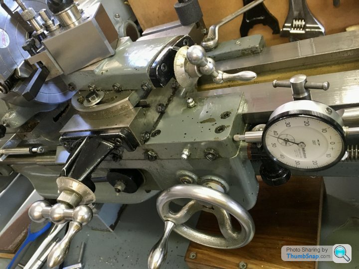
He was using carbide inserts (mitutoyo) iirc. There were some other spots where you could tell they were a different hardness but the base was...profoundly different. Change in sound is putting it mildly - was ringing like a bell.Made some more progress on the valve chest. I used the setting ring, and double checked using the depth to face method. All checked out to well within 0.001”
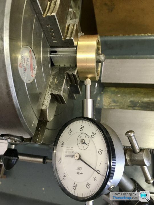
I set up for facing to a set depth using my end stop and a DTI on the saddle. Then forgot to tighten the tool holder, so it moved during the first cut. Ended up machining to a scribed line. Again.
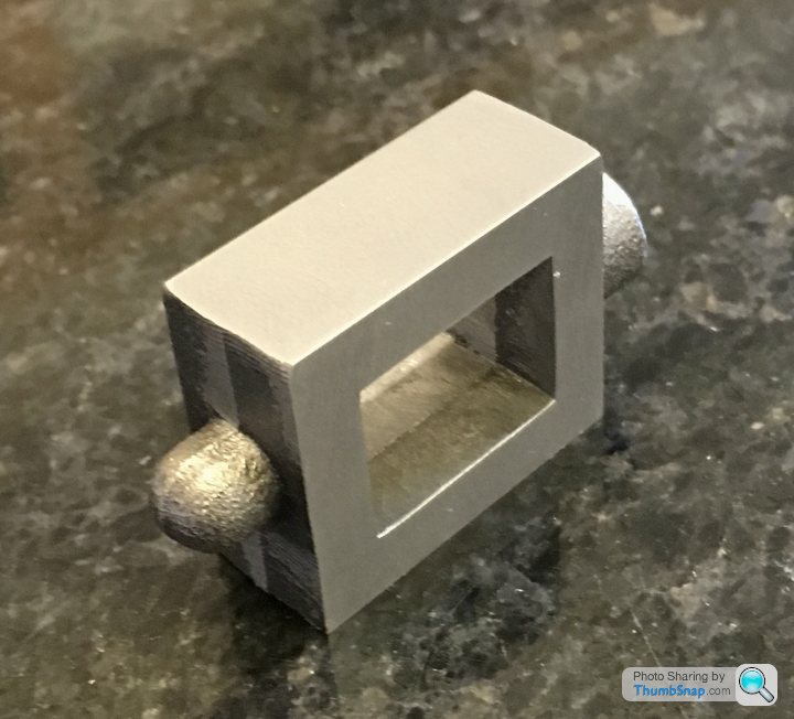
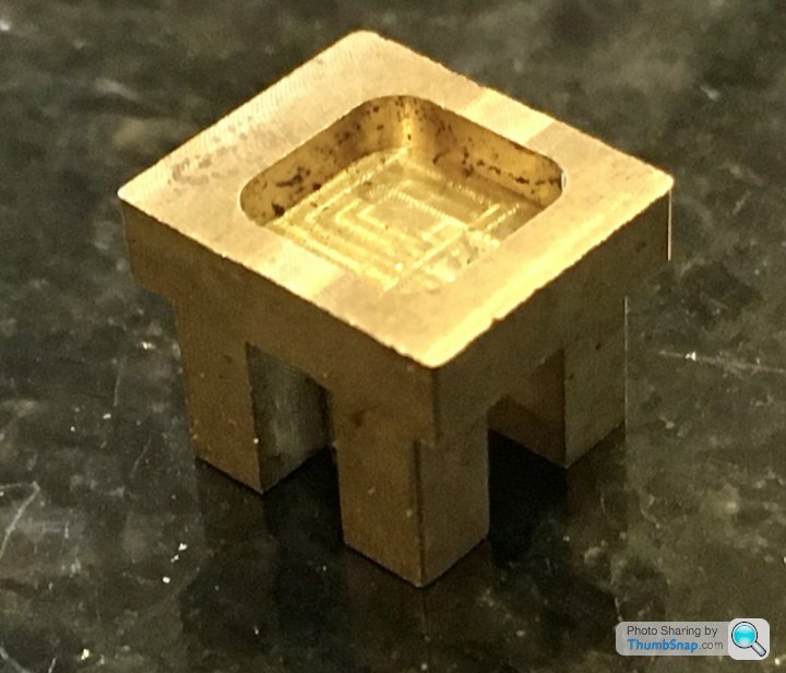
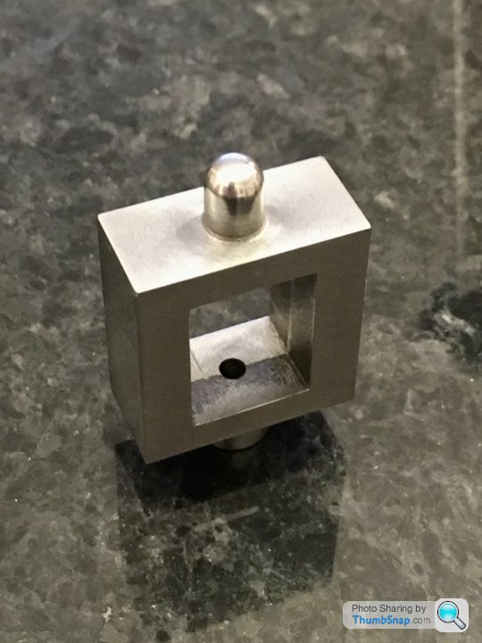
Anyway, turned the part around and drilled, reamed and tapped the valve rod holes in one setup:
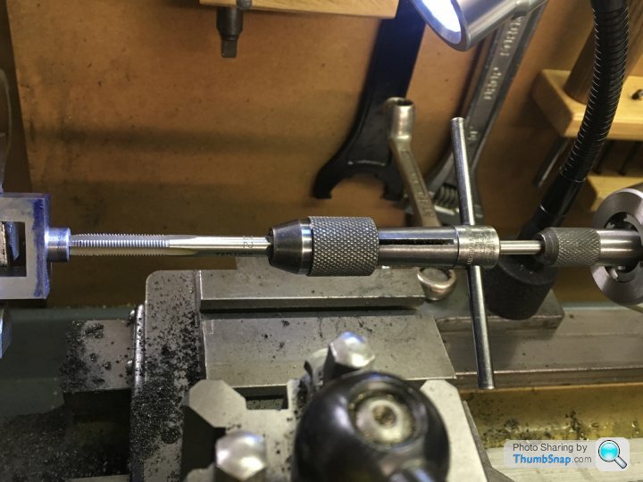
The holes seemed to be co-axial, and the 1/8” rod is a nice fit:


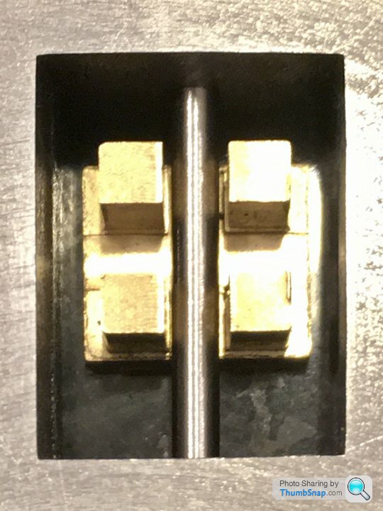
Slide valve seems to be central, so that’s OK:
It is a hair too long, purely due to the DTI/tool holder screw up, but it’s not noticeable, nor does it impact any other fit. I added 0.5mm excess to the sides to allow for the Aluminium lagging plate:
A side effect of this is that the cover plate will be fractionally too small once cleaned up:
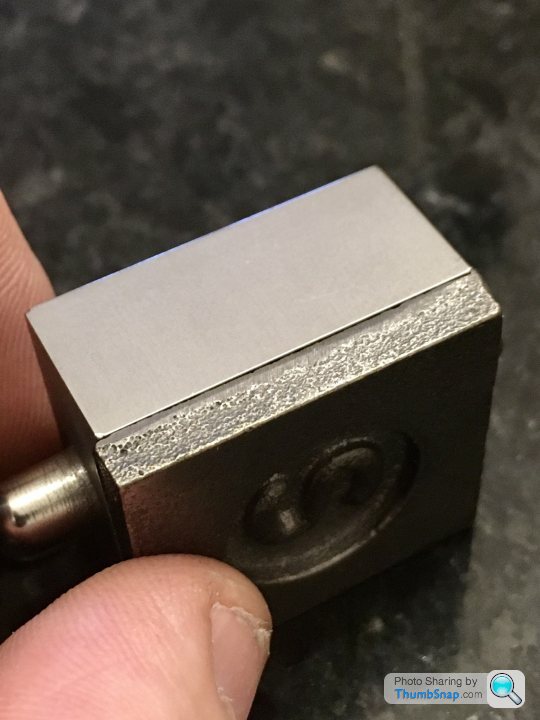
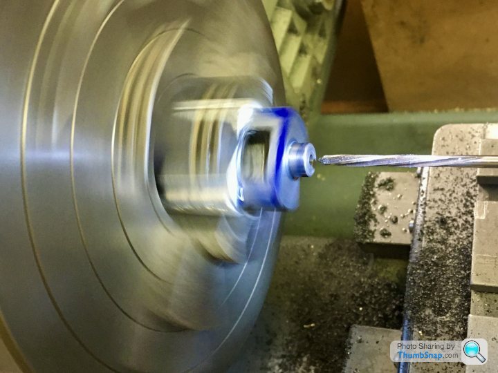
So long as it’s equal all around I guess it’ll be ok. BTW the domed tip boss was filed to shape while spinning in the chuck:
So now Im wondering about the best way to drill the mounting holes for the valve chest and cover. I don’t want to end up with it on the piss, like it is on the cover of my book. I’m thinking of clamping everything together, and drilling through as a stack.
I set up for facing to a set depth using my end stop and a DTI on the saddle. Then forgot to tighten the tool holder, so it moved during the first cut. Ended up machining to a scribed line. Again.
Anyway, turned the part around and drilled, reamed and tapped the valve rod holes in one setup:
The holes seemed to be co-axial, and the 1/8” rod is a nice fit:
Slide valve seems to be central, so that’s OK:
It is a hair too long, purely due to the DTI/tool holder screw up, but it’s not noticeable, nor does it impact any other fit. I added 0.5mm excess to the sides to allow for the Aluminium lagging plate:
A side effect of this is that the cover plate will be fractionally too small once cleaned up:
So long as it’s equal all around I guess it’ll be ok. BTW the domed tip boss was filed to shape while spinning in the chuck:
So now Im wondering about the best way to drill the mounting holes for the valve chest and cover. I don’t want to end up with it on the piss, like it is on the cover of my book. I’m thinking of clamping everything together, and drilling through as a stack.
Glue em all together with loctite and then drill, clearance drill cover and chest,careful with depth,then tap cylinder. Disassemble with heat.
Have you drilled domed valve rod guide 1/8th ? If so plans have changed. My problem was 3/32 drills are short so I struggled to drill it through the valve gland (Ooer missus).

Have you drilled domed valve rod guide 1/8th ? If so plans have changed. My problem was 3/32 drills are short so I struggled to drill it through the valve gland (Ooer missus).
fourfoldroot said:
Glue em all together with loctite and then drill, clearance drill cover and chest,careful with depth,then tap cylinder. Disassemble with heat.
Have you drilled domed valve rod guide 1/8th ? If so plans have changed. My problem was 3/32 drills are short so I struggled to drill it through the valve gland (Ooer missus).
No, the hole in the dome has to be smaller than 1/8”, because the 1/8” rod has to be threaded half way down to give an adjustment method for the slider. The top end has to be smaller than the root diameter of that thread in order to get the die down it. I used a Dormer TiN coated 2.4mm drill, not 3/32” (2.38mm). I paid particular attention to cleaning the face so the drill wouldn’t wander. The end of the rod has to be turned to fit the upper hole, so The 0.02mm difference is irrelevant. I don’t really get why the lower end (1/8”) hole needs reaming, yet the top one doesn’t. They both locate the valve rod as a sliding fit. If they didn’t, the upper hole would be redundant.Have you drilled domed valve rod guide 1/8th ? If so plans have changed. My problem was 3/32 drills are short so I struggled to drill it through the valve gland (Ooer missus).
Yes,good, it’s just from pic with valve and rod in place it looked like it went through. The valve rod gave me probs too. I found the stainless hard to thread without stripping, and turning the 3/32-2.38 mm end. Any more than a few mm sticking out the chuck and it would ride up over the cutter. Should be better with collets.
fourfoldroot said:
Yes,good, it’s just from pic with valve and rod in place it looked like it went through. The valve rod gave me probs too. I found the stainless hard to thread without stripping, and turning the 3/32-2.38 mm end. Any more than a few mm sticking out the chuck and it would ride up over the cutter. Should be better with collets.
Yes, I'm not looking forward to machining the stainless, but if I screw it up it's only a couple of quid to get more.The photo is a bit misleading - the 1/8" rod is just touching the surface. Should have clarified.
Thanks
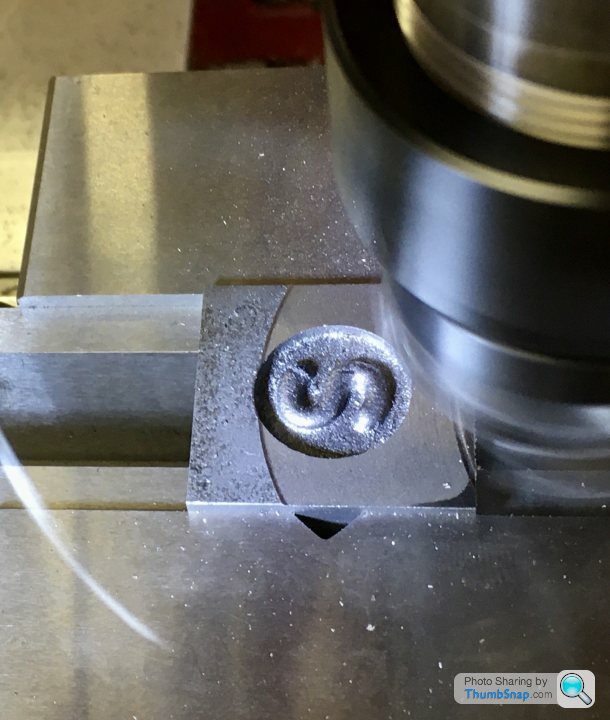
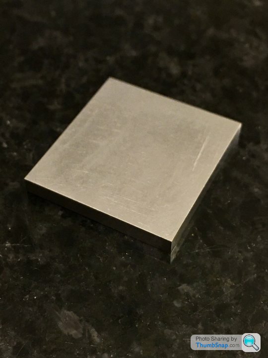
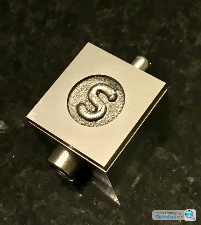
Didn’t have much time this evening, so I just squared and flatted the valve chest cover. First job was to mill the edges; first opposite pair I face-milled vertically, then clamped those faces horizontally and side-milled the other two. I made sure the “S” Circle was central:

Then fly-cut the faces to the right thickness:
The finish using the power feed is really nice - the leading cut obviously takes the majority of the material off, and the trailing cut just skims the surface. I think this must mean that my tramming efforts weren’t so bad after all. I finished by lightly rubbing on wet and dry on the surface plate:
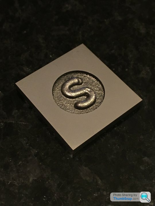
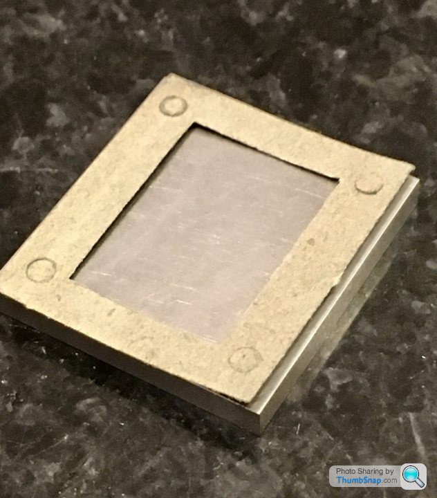
It’s a shame that to *just* completely clean up the side edges, it went undersize. I’ve tried to make the gap equal all around. Not to plan, but there was no way around it I could think of:
If Im careful, I can get the cover to stick to the chest on its own:

The gasket is not a great fit, and I suppose I may have to re-position the holes very slightly, but it shouldn’t be a big issue.
I’ll try to get the cylinder caps done next, then spend the weekend’s workshop time drilling all the mounting holes. I think calculation of all the co-ordinates will be at least a two-mug-of-tea job.
Then fly-cut the faces to the right thickness:
The finish using the power feed is really nice - the leading cut obviously takes the majority of the material off, and the trailing cut just skims the surface. I think this must mean that my tramming efforts weren’t so bad after all. I finished by lightly rubbing on wet and dry on the surface plate:
It’s a shame that to *just* completely clean up the side edges, it went undersize. I’ve tried to make the gap equal all around. Not to plan, but there was no way around it I could think of:
If Im careful, I can get the cover to stick to the chest on its own:
The gasket is not a great fit, and I suppose I may have to re-position the holes very slightly, but it shouldn’t be a big issue.
I’ll try to get the cylinder caps done next, then spend the weekend’s workshop time drilling all the mounting holes. I think calculation of all the co-ordinates will be at least a two-mug-of-tea job.
Love it. Having done some very basic work on a lathe and milling machine, but nothing at all complicated, watching the thought processes an methods used to achieve the required cuts is fascinating.
I am amazed that the valve cover casting dims are that mean that you don't have the 0.5mm either side, but it looks smart with a small even step as you have it. Unlike the photo of the built one in the opening posts as you say!
Daniel
I am amazed that the valve cover casting dims are that mean that you don't have the 0.5mm either side, but it looks smart with a small even step as you have it. Unlike the photo of the built one in the opening posts as you say!
Daniel
dhutch said:
dr_gn said:
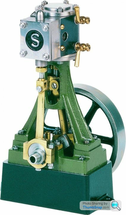
Almost criminal now I've seen it. The valve chest is pissed up to the cylinder block too. It's almost like they have done it deliberately to make those less able feel good about themselves!Daniel
dr_gn said:
Don't know. It's one of the images for the 10V on their website too. You'd have thought they'd have used a better example.
The paint also looks awful somehow. But also I don't notice it reading the opening post! And usually I noticed this sort of thing.Maybe that's the level of finish on the built ones?
Even if the valve rod is at that angle, it won't effect the running noticeably. But yours well look a lot nicer on close inspection!
Daniel
I don’t know why the cover is too small. I adjusted everything else to fit the cover.
 [url]
[url]
 |https://thumbsnap.com/Hse2W59c[/url]
The close up photos are very unforgiving ! The paint looks like I applied it with a stick! In the flesh it isn’t too bad. Still, it was my first time using a lathe since making an adjustable spanner 46 years ago at school.

[url]|https://thumbsnap.com/Hse2W59c[/url]The close up photos are very unforgiving ! The paint looks like I applied it with a stick! In the flesh it isn’t too bad. Still, it was my first time using a lathe since making an adjustable spanner 46 years ago at school.
Yes, yours looks great.
The width of my valve chest was defined by the width of the cylinder port face (exactly 1" on the drawing, which mine is). The 1" dimension is in turn defined from the cylinder axis to valve face (that's also correct to within 0.011").
Then there is plus 0.5 mm per side to allow for flush fitting of the lagging.That figure is what the valve chest is machined to. The height of the valve chest is fine - the cover plate had plenty of excess on that, but the width was marginal to start with.
So long as the cover ends up central, the slight step around it doesn't bother me - in fact it breaks up the blocky look of the assembly a bit.
Yes, there is something quick nice if you can achieve it in having the individually machined parts meeting near perfect, however as you say in this particular example due to the scaling it does end up with the valve chest and cover looking disproportionately large, which the small step reduces significantly. I think by the time you are talking about various ways to get a really nice finish, you have won the game and any answer is a good one!
Our own steam engine (non model) is a two cylinder compound, piston valve on the hp slide valve on the lp. So the total cylinder block is in.fact in six parts. Piston valve block, hp cyl block, lp cyl block, lp valve seat, chest, and cover. They all line up top and bottom within a thou or so, and its a very nice thing to see. Engine is driving a narrowboat, 4.5+7.5x4, wp of 200psi.
Daniel
Gassing Station | Scale Models | Top of Page | What's New | My Stuff