Stuart 10V Vertical Steam Engine
Discussion


So I made a start on the cylinder covers, firstly the top one, because It’s much less critical than the lower. The only feature that’s important is the spigot that fits into the cylinder.
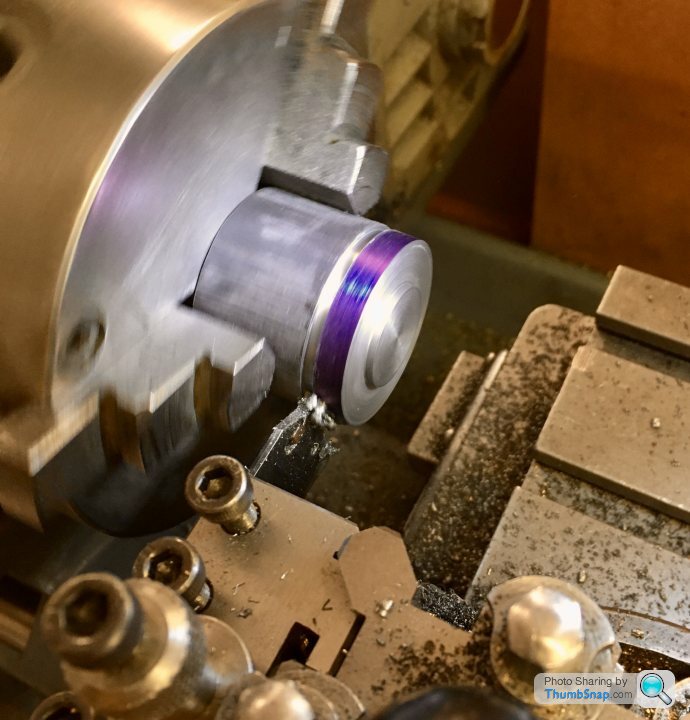
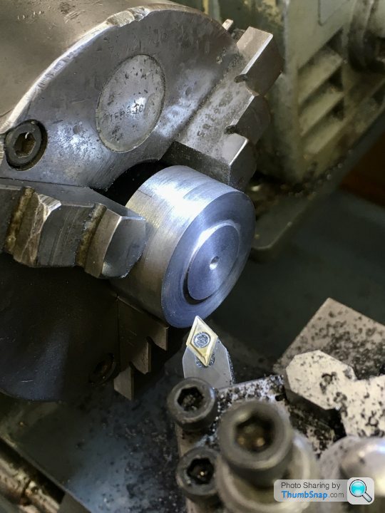
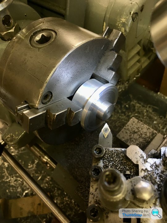
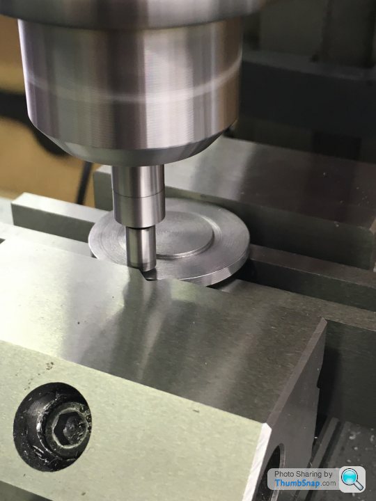
I chucked the cast iron bar in the three jaw, faced and turned to size: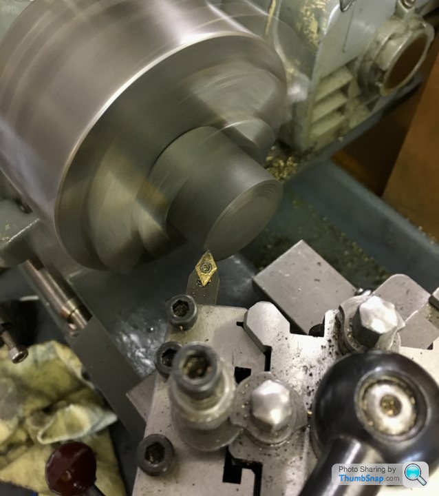
Then turned the inner spigot, to be a good fit in the bore diameter:
I started to part-off the job, with the intention of reversing it in the chuck and turning the top features. It seemed to be going well, so I decided to part it in two stages- the first to form the upper boss, then move the tool back and part off from the stock:
It actually worked pretty well, but some clean-up was required anyway, and due to this the top boss is a bit short (not that it matters). On balance I should have parted off, reversed and just turned the other side as normal. In the end my initial method could have worked, but as usual didn’t quite.
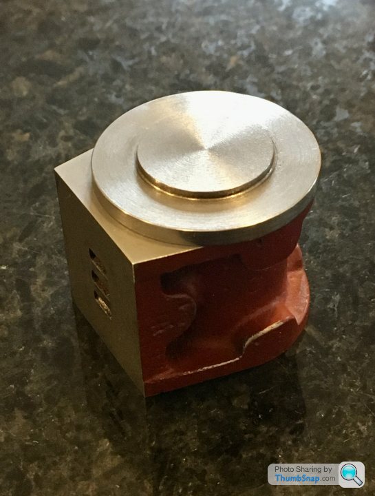
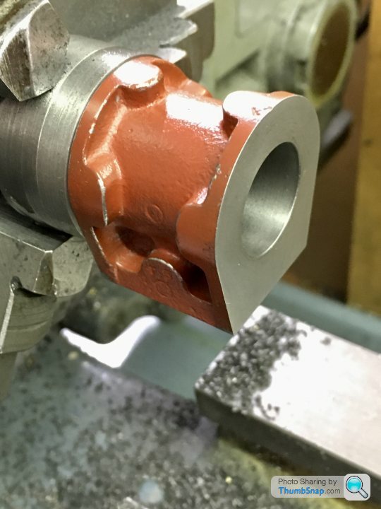
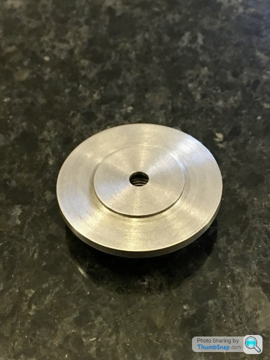
Anyway, it fits the cylinder, and it’s gasket, and it looks ok:
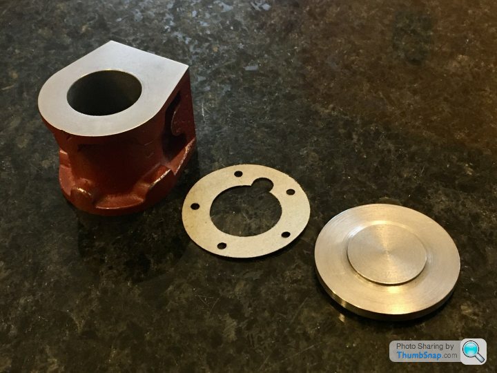
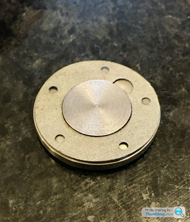
I was hoping the overhang would be concentric around the circular portion, so the lagging plate would be a flush fit. Unfortunately it’s not the case:
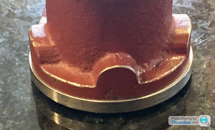
So some filing will be needed. Pretty sure I setup the casting pretty much as good as it could have been, so I wonder if the cast surface is slightly bulged? No big deal.
So next the lower cover. I still don’t really know how to reverse and hold it.
I chucked the cast iron bar in the three jaw, faced and turned to size:
Then turned the inner spigot, to be a good fit in the bore diameter:
I started to part-off the job, with the intention of reversing it in the chuck and turning the top features. It seemed to be going well, so I decided to part it in two stages- the first to form the upper boss, then move the tool back and part off from the stock:
It actually worked pretty well, but some clean-up was required anyway, and due to this the top boss is a bit short (not that it matters). On balance I should have parted off, reversed and just turned the other side as normal. In the end my initial method could have worked, but as usual didn’t quite.
Anyway, it fits the cylinder, and it’s gasket, and it looks ok:
I was hoping the overhang would be concentric around the circular portion, so the lagging plate would be a flush fit. Unfortunately it’s not the case:
So some filing will be needed. Pretty sure I setup the casting pretty much as good as it could have been, so I wonder if the cast surface is slightly bulged? No big deal.
So next the lower cover. I still don’t really know how to reverse and hold it.
fourfoldroot said:
Knock up something like this. Turn it to spigot size,slit it, and when you put it back in 3 jaw you can do what you like with perimeter and other side. 
Someone on the ME forum just posted the exact same thing, but in CAD. I'll do it tomorrow.
Cheers!
ETA I'm scanning some of my old '70s & '80's F1 pictures in at the moment for the F1M forum. Many of them taken by my Dad with his trusty Olympus Trip 35.

fourfoldroot said:
Forgot to add, when you make split collet, centre punch it adjacent to jaw one on chuck, so when you put it back in it remains concentric. If it is good fit for spigot, you won’t be far out. I mark all mandrels so they go back in same position,even a good 3 jaw is a bit out.
Thanks, yes that was mentioned too. I can't use my three jaw for consistent work, so I'll have to be careful. Ill also have to remember to break the edges of the part so it fits snugly into the corners of the fixture.Nice collection of cameras by the way - you still use film? I've got my Dad's Olympus here in a drawer, still in its original zipped bag.
dr_gn said:
Thanks, yes that was mentioned too. I can't use my three jaw for consistent work, so I'll have to be careful. Ill also have to remember to break the edges of the part so it fits snugly into the corners of the fixture.
Nice collection of cameras by the way - you still use film? I've got my Dad's Olympus here in a drawer, still in its original zipped bag.
Oh yes. Digital for utility. Film for fun. The Trip 35 do not need a battery and if stored in the dark, the photocells round the lens do no degrade. They are a good little camera and have their own online fan clubs.Nice collection of cameras by the way - you still use film? I've got my Dad's Olympus here in a drawer, still in its original zipped bag.
fourfoldroot said:
dr_gn said:
Thanks, yes that was mentioned too. I can't use my three jaw for consistent work, so I'll have to be careful. Ill also have to remember to break the edges of the part so it fits snugly into the corners of the fixture.
Nice collection of cameras by the way - you still use film? I've got my Dad's Olympus here in a drawer, still in its original zipped bag.
Oh yes. Digital for utility. Film for fun. The Trip 35 do not need a battery and if stored in the dark, the photocells round the lens do no degrade. They are a good little camera and have their own online fan clubs.Nice collection of cameras by the way - you still use film? I've got my Dad's Olympus here in a drawer, still in its original zipped bag.
So after some false starts, I finished the lower cover this evening.
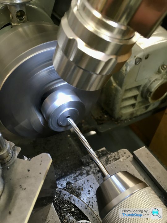
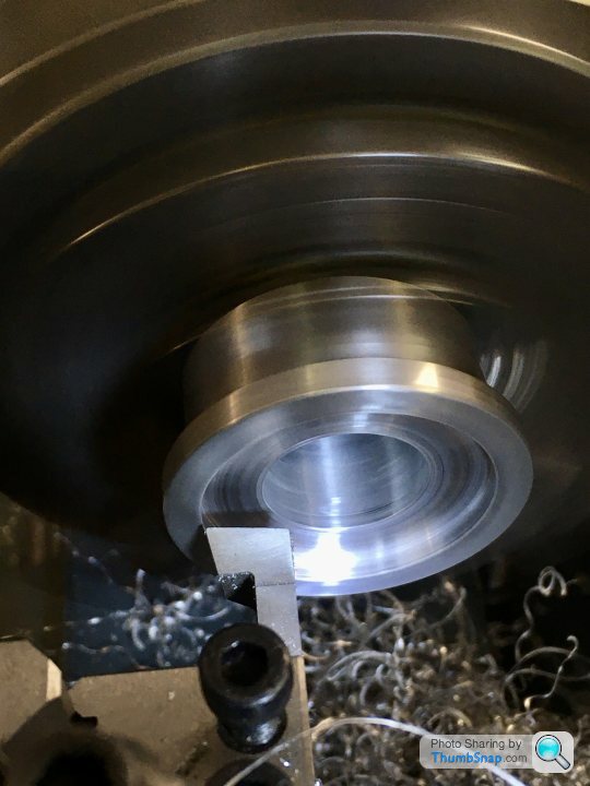
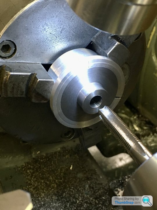
Turned the inner spigot, drilled and reamed:
Close fit into the bore, all ok there:
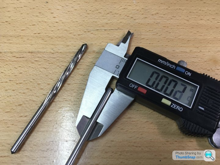
5/32” rod supplied was oversized, but I eventually got it to fit by some polishing in the chuck:
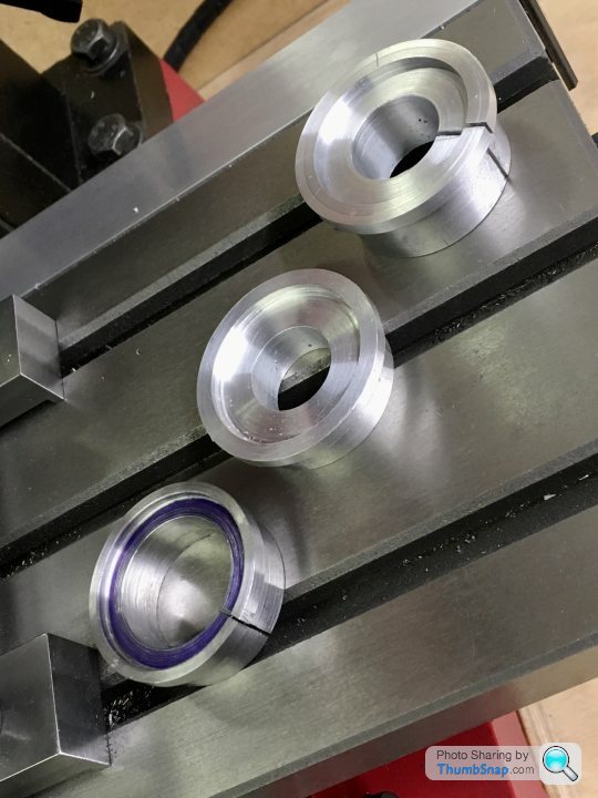
Then, after two failed attempts, made the split bush to hold the cover while machining the reverse side:
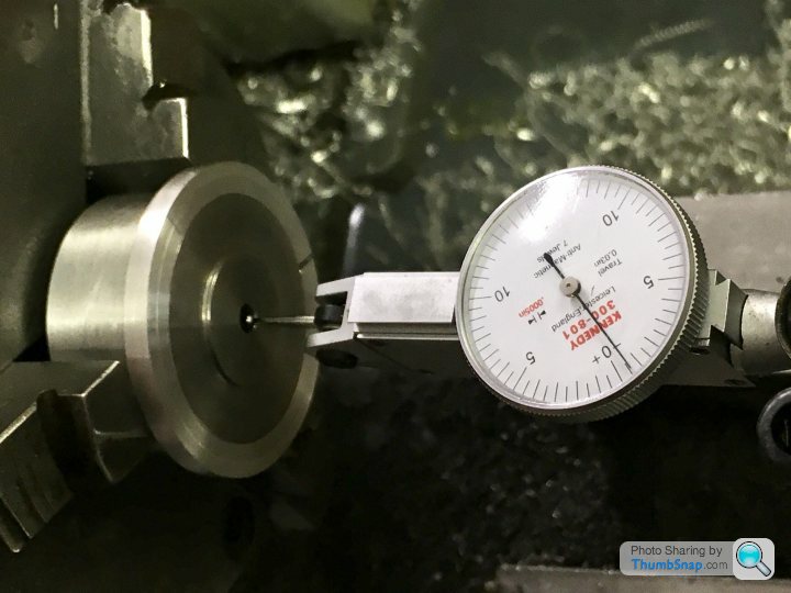
Matched to jaw #1, I checked runout of the coverWith a DTI. Virtually nothing this time, much less than 0.001”. I then pushed the rod into the hole and checked that:
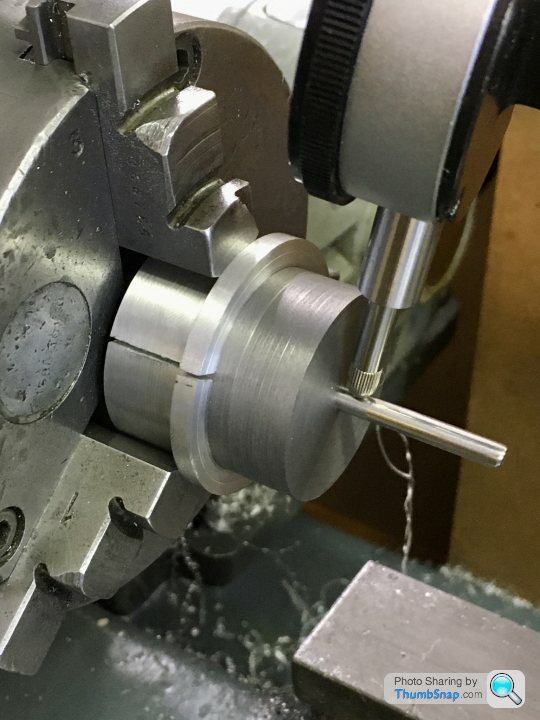
Quickly wished I hadn’t; 0.004” runout.
Anyway, I can’t keep re-doing this cover. It’s getting the better of me and I need to move on. It must have been the drill that wandered, despite me being very careful.
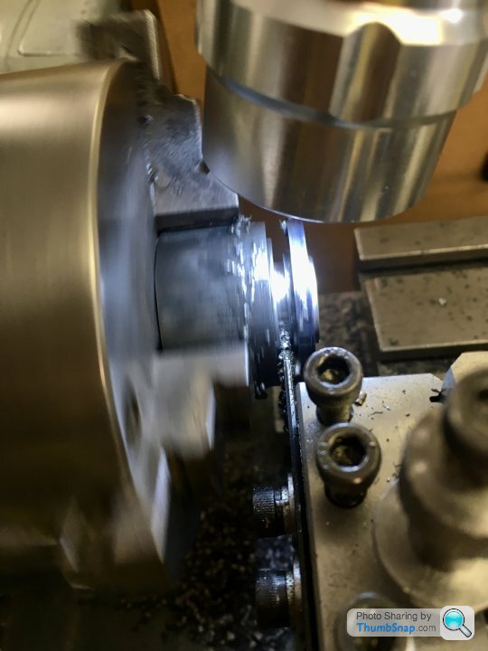
I made the recess the right depth for the cover, so it was a simple matter to turn down the boss:
Close fit in the standard; ok:
Drill & tap:
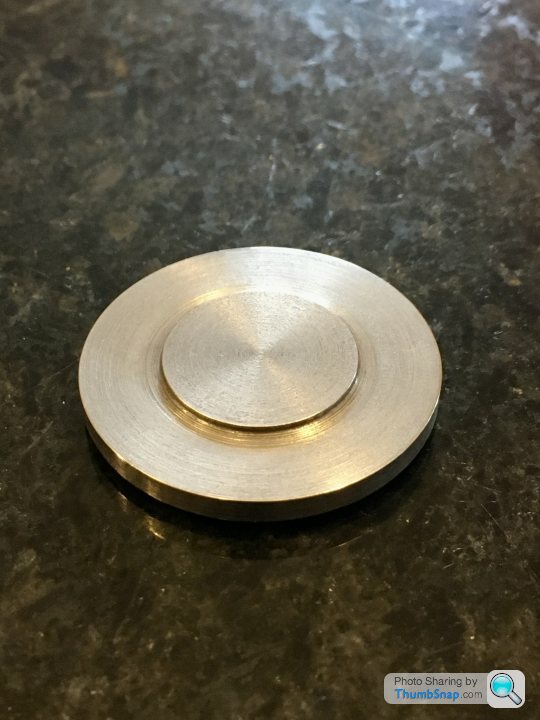
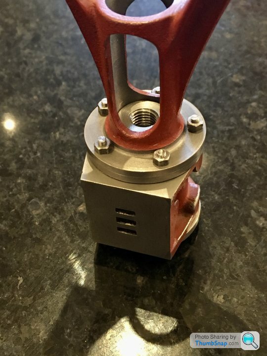
Finished:
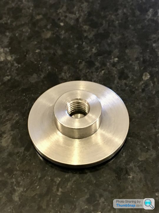

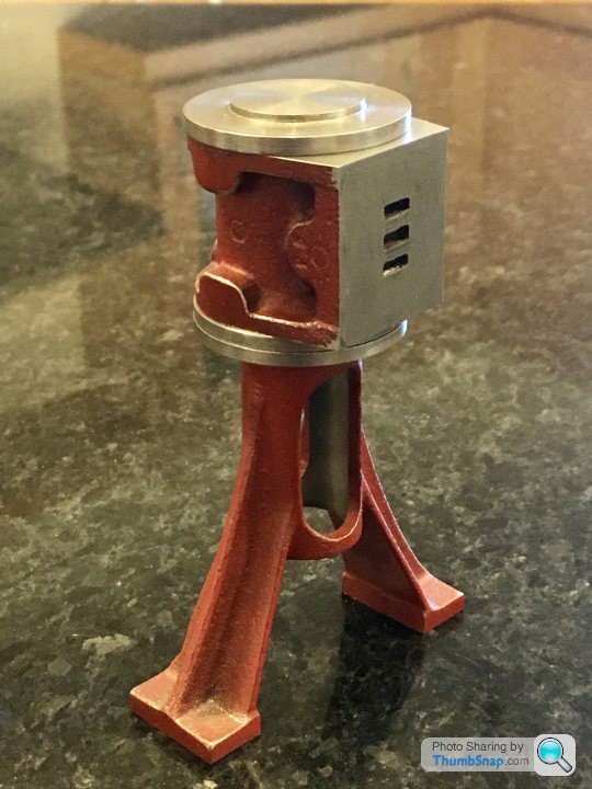
The standard diameter is a fraction more. I might turn it down to match - it should also reduce the depth of the edge flaw In the casting a bit.
The reamed hole is very shallow, significantly less than its diameter (as per the drawing). I’m wondering now if it was meant to be reamed at all. The drawing doesn’t say so, I just assumed it did. The packing nut also isn’t specified as a reamed hole. I think maybe they should be a close fit, but not to a ream tolerance. The combined length of the assembly, plus packing Would probably form a good enough sliding location. We will see how it assembles I guess.
Turned the inner spigot, drilled and reamed:
Close fit into the bore, all ok there:
5/32” rod supplied was oversized, but I eventually got it to fit by some polishing in the chuck:
Then, after two failed attempts, made the split bush to hold the cover while machining the reverse side:
Matched to jaw #1, I checked runout of the coverWith a DTI. Virtually nothing this time, much less than 0.001”. I then pushed the rod into the hole and checked that:
Quickly wished I hadn’t; 0.004” runout.
Anyway, I can’t keep re-doing this cover. It’s getting the better of me and I need to move on. It must have been the drill that wandered, despite me being very careful.
I made the recess the right depth for the cover, so it was a simple matter to turn down the boss:
Close fit in the standard; ok:
Drill & tap:
Finished:
The standard diameter is a fraction more. I might turn it down to match - it should also reduce the depth of the edge flaw In the casting a bit.
The reamed hole is very shallow, significantly less than its diameter (as per the drawing). I’m wondering now if it was meant to be reamed at all. The drawing doesn’t say so, I just assumed it did. The packing nut also isn’t specified as a reamed hole. I think maybe they should be a close fit, but not to a ream tolerance. The combined length of the assembly, plus packing Would probably form a good enough sliding location. We will see how it assembles I guess.
I put the cover back in the fixture and put a finger gauge in what’s left on the reamed hole:
I’m getting a maximum reading of about 0.00075”. I suppose my previous reading could have been made worse by any clearance between the rod and hole, and error in the rod itself. Plus I guess a small inherent error with the split ring itself. Anyway, I don’t think I can get better than that.
I’m getting a maximum reading of about 0.00075”. I suppose my previous reading could have been made worse by any clearance between the rod and hole, and error in the rod itself. Plus I guess a small inherent error with the split ring itself. Anyway, I don’t think I can get better than that.
All looking good. The gland packing is the forgiveness factor. Again it’s all part of the learning curve. I’m a bit of a perfectionist and bits like this troubled me, but it all worked when finished. When model engineering was in it’s heyday, most people did not have dial indicators or 0.0001 micrometers, they just had a steel rule and calipers but still built fantastic working models.
Thanks both. Yes, it's all about experience; the drawings have the bare-bones dimensions, and it's up the builder to figure out what's important.
I mentioned over on the ME forum that I can't see why the cover hole is critical at all. The assembled piston, rod and crosshead take all axial and rotations normal to the axis' degrees of freedom out of the system when assembled in their bores, so adding a reamed hole in the middle just seems like an over constraint. I think it's just for the seal, which conforms to any runout anyway, and fills any slight fit errors.
Still, I must admit I'm glad that the runout is in fact less than 0.001" after all that. I was gutted when I saw 0.004" on the DTI.
It'll be interesting to see if it all slides freely without opening the cover hole up!


OK - the bore honing is for another day!
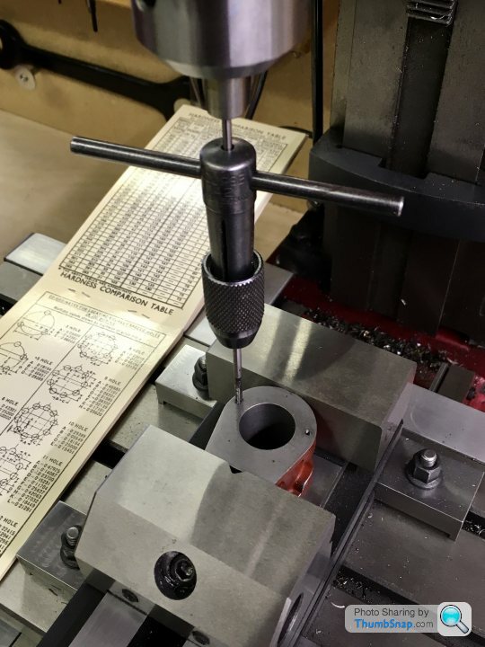
Today I co-ordinate drilled the covers, standard and cylinder block. Started by triple checking my calculations, then set the cylinder in the vice and finding the centre of the bore, which I set to be 0,0
Dotted the co-ordinates as a sanity check:
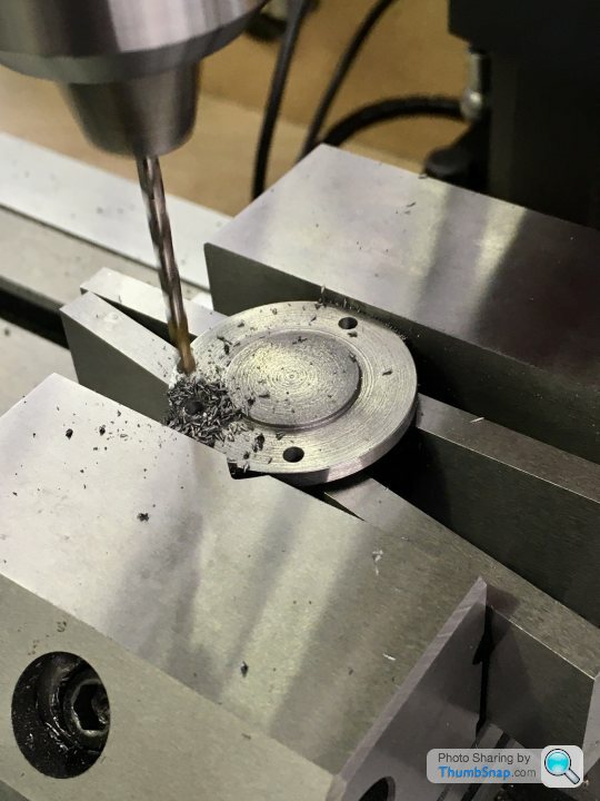
The gasket PCD was a bit small, but after checking yet again I could find nothing wrong with my calcs, so went ahead and drilled and tapped each of the 10 holes in turn:
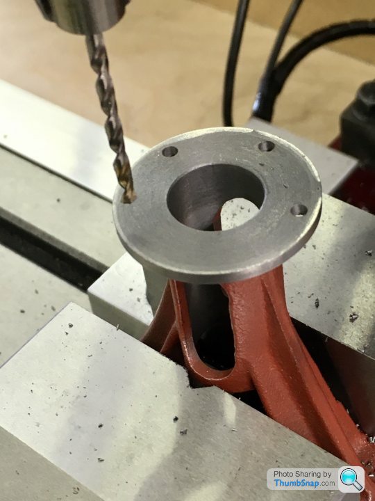
Then, on to the top cover. Used the inside of the vice jaws as the y-reference:
Clearance drilled:
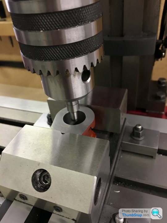
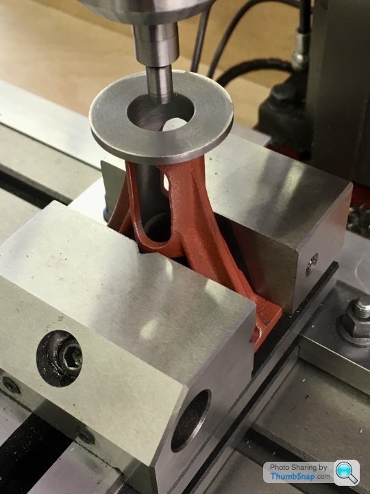
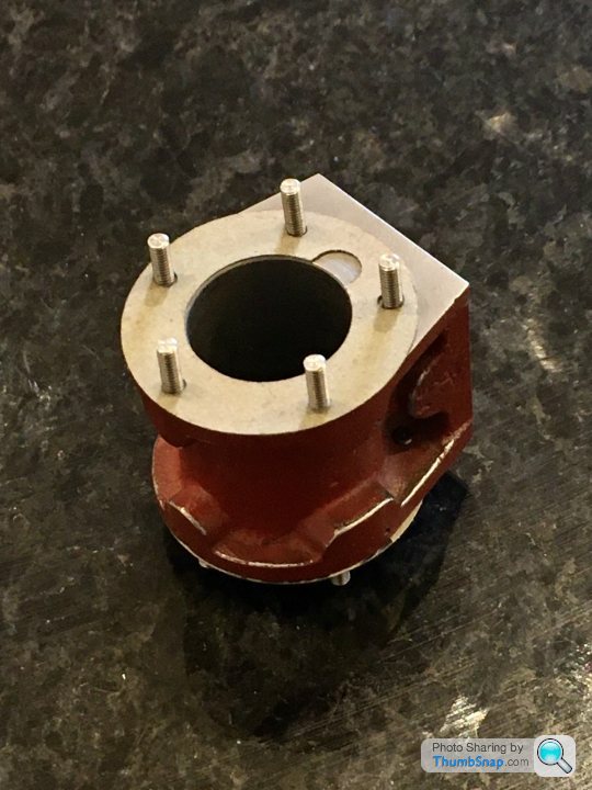
Same with the lower cover, but gripped by the lower boss:
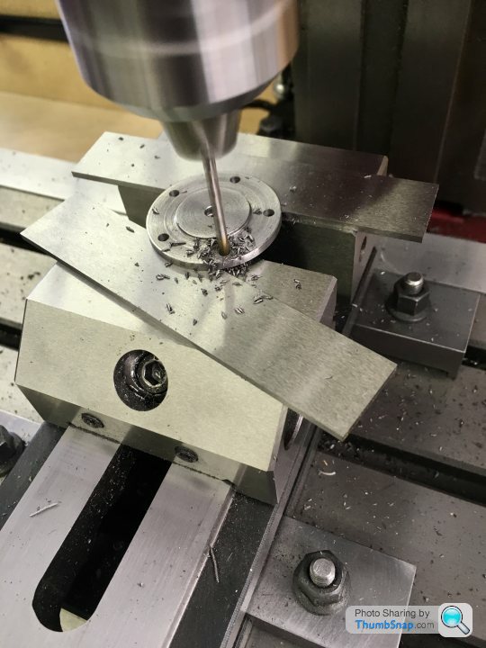
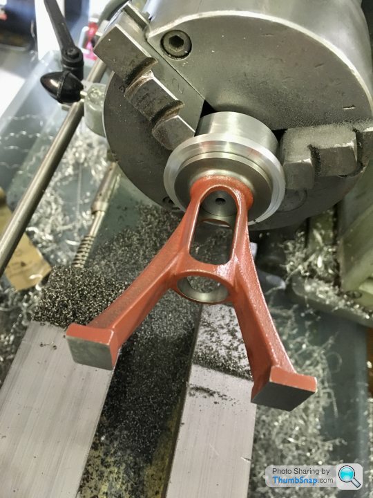
Then the standard - I put it in the vice using the feet edges as a reference for clocking the hole array:
Clearance drilled :
All de-burred:
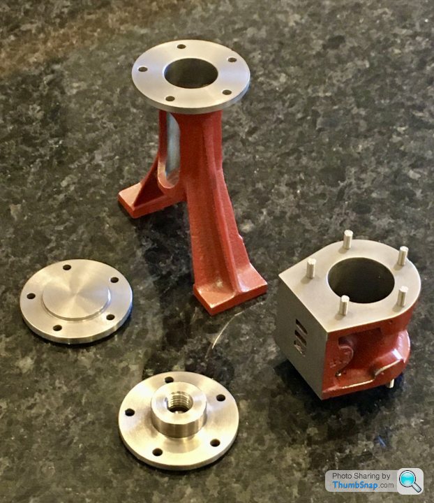
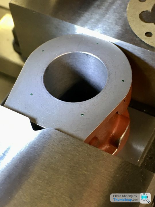
Studs test fitted, everything clicks into place, although the lower cover only fits in two orientations:
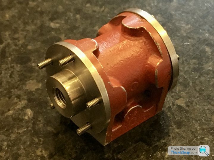
The gaskets have a bit of stretch, and do in fact fit ok:
The lower nuts fit, but their corners *just* touch the machined radius unfortunately. I can correct it though:
But all in all, happy with that.

Today I co-ordinate drilled the covers, standard and cylinder block. Started by triple checking my calculations, then set the cylinder in the vice and finding the centre of the bore, which I set to be 0,0
Dotted the co-ordinates as a sanity check:
The gasket PCD was a bit small, but after checking yet again I could find nothing wrong with my calcs, so went ahead and drilled and tapped each of the 10 holes in turn:
Then, on to the top cover. Used the inside of the vice jaws as the y-reference:
Clearance drilled:
Same with the lower cover, but gripped by the lower boss:
Then the standard - I put it in the vice using the feet edges as a reference for clocking the hole array:
Clearance drilled :
All de-burred:
Studs test fitted, everything clicks into place, although the lower cover only fits in two orientations:
The gaskets have a bit of stretch, and do in fact fit ok:
The lower nuts fit, but their corners *just* touch the machined radius unfortunately. I can correct it though:
But all in all, happy with that.
Blooming marvellous, and a credit to your DROs that you can coordinate drill that accurately.
On our full size engine the holes throughout the whole thing are nowhere near, new to us in 1991, the cylinder covers on engine and pump have clearly been drilled through, almost by eye as far as I can see, and only fit one way, index them round a hole or two and you can often have miss-alignments of a 1-2mm on a 1/4" stud which obviously then no longer clears! Same elsewhere, such as rocker arms for the crosshead driven pumps. Everything is numbered, with number stamps or 1-4 center puch marks, and woe betide you you try and put them in the wrong order!
Daniel
Thanks - yes I’ve come to regard those DROs as a basic human right. I can see why things aren’t consistent if they’ve been made on machines with hand wheels and backlash (like my lathe in fact). All the stuff that I’ve turned isn’t very consistent: I’ve got to re-visit the standard Upper diameter to get it to match the lower cover for example.
I think a lot of old machinery was the same in terms of assembly. In fact even today in aerospace applications things like replacement panels or bits of sub structure have to be fettled or drilled to suit other parts before they’ll fit.
I think a lot of old machinery was the same in terms of assembly. In fact even today in aerospace applications things like replacement panels or bits of sub structure have to be fettled or drilled to suit other parts before they’ll fit.
Gassing Station | Scale Models | Top of Page | What's New | My Stuff