Stuart 10V Vertical Steam Engine
Discussion


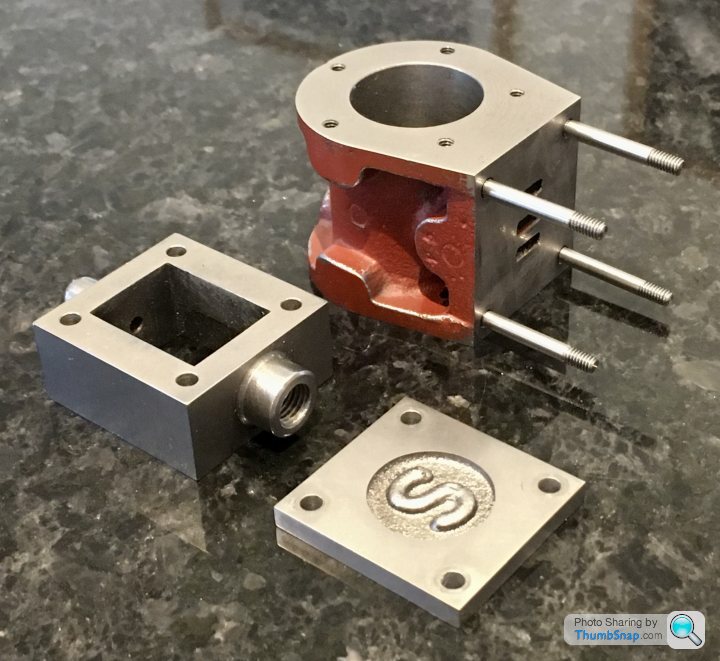
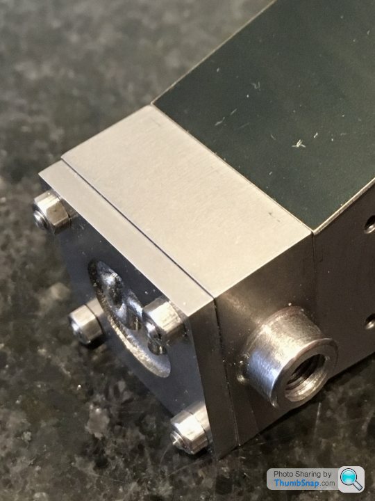
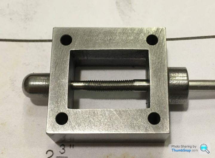
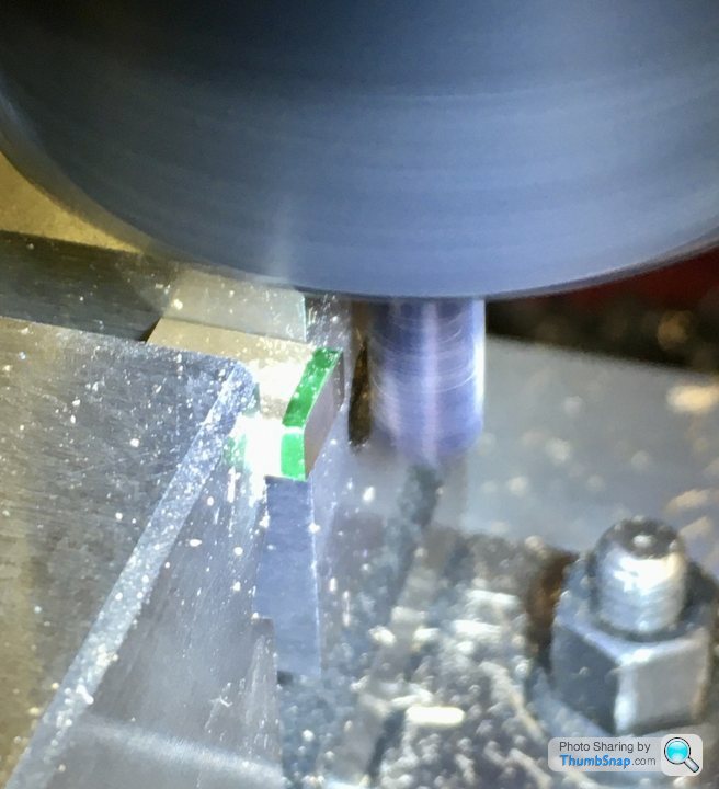
So on to the valve chest fitting. Began by clamping the cylinder in the vice using some parallels to get the top face flat:
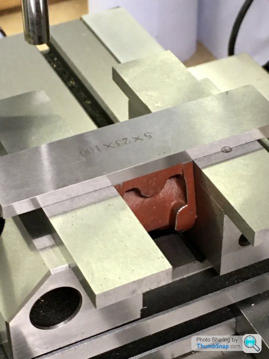
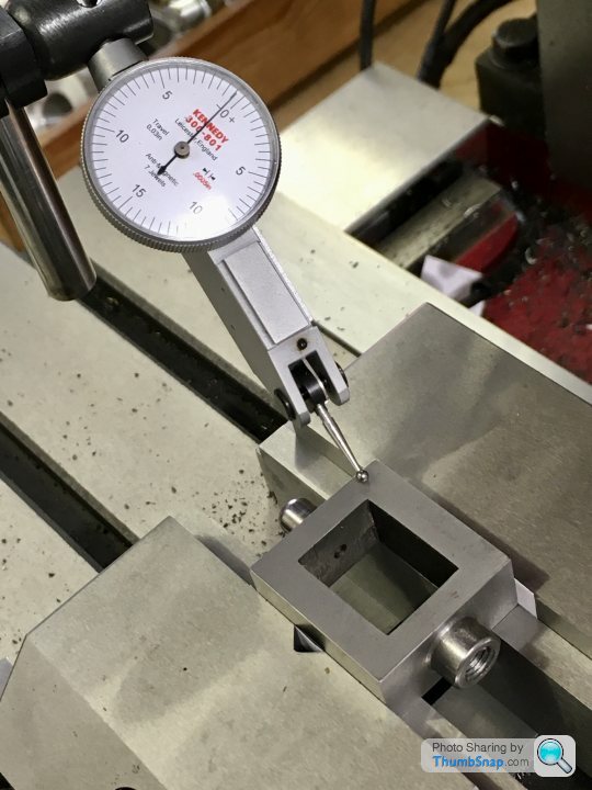
Checked for flatness:
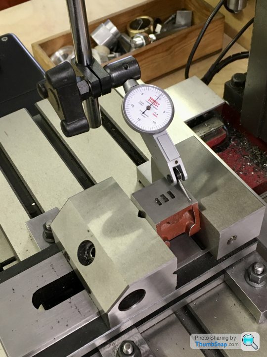
And got the centre using the edge finder:
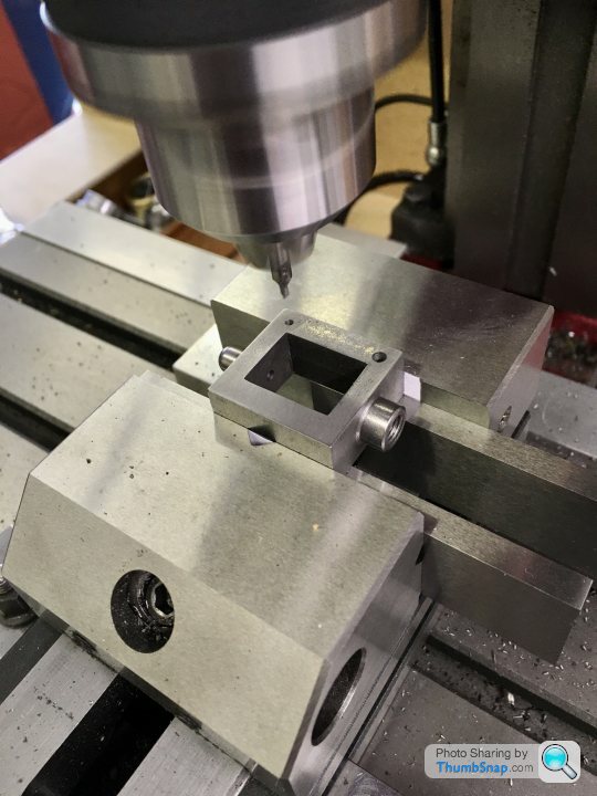
Then co-ordinate drilled and tapped in one setting using the DROs:
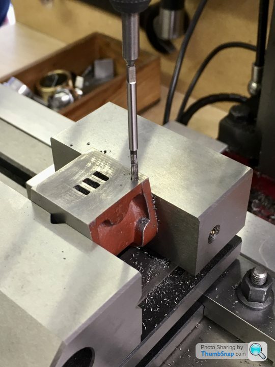
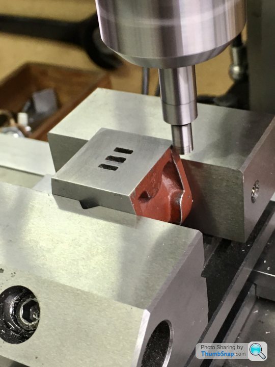
Same with the valve chest:
And the cover:
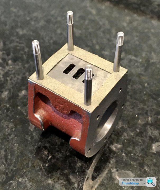
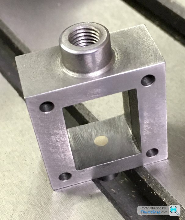
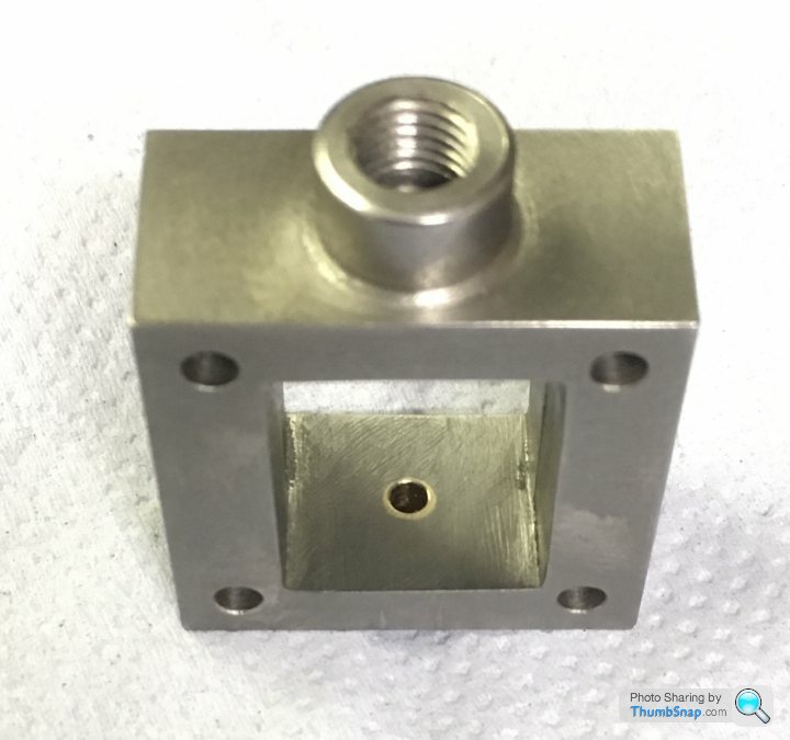
Fitted the studs temporarily:
Gaskets fit, so must be about right:
It all slides together nicely, and seems to be central:
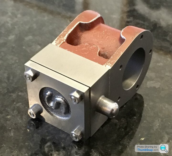
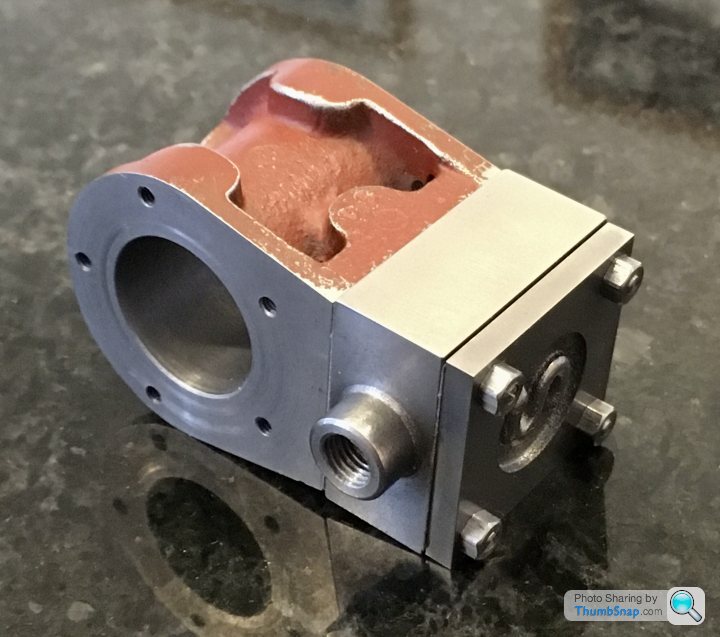
And the jacket is a flush fit too:
Next job will be fitting the main bearings and standard to the sole plate.
Checked for flatness:
And got the centre using the edge finder:
Then co-ordinate drilled and tapped in one setting using the DROs:
Same with the valve chest:
And the cover:
Fitted the studs temporarily:
Gaskets fit, so must be about right:
It all slides together nicely, and seems to be central:
And the jacket is a flush fit too:
Next job will be fitting the main bearings and standard to the sole plate.
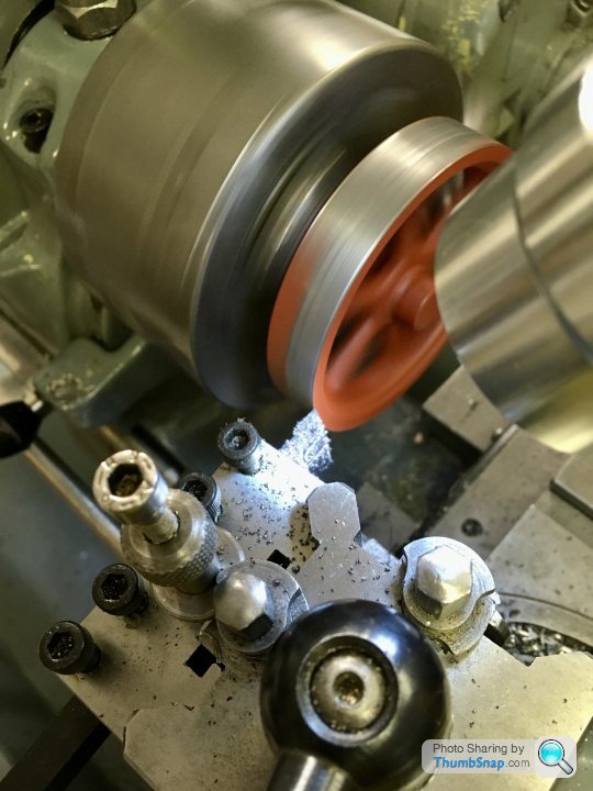
Got a bit sidetracked with this, but made another start, this time on the flywheel:
Expanded the 3-jaw Chuck to clamp the inside of the rim, and turned true:
Drilled the bore:
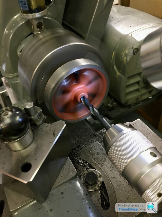
Reamed to suit the crankshaft:
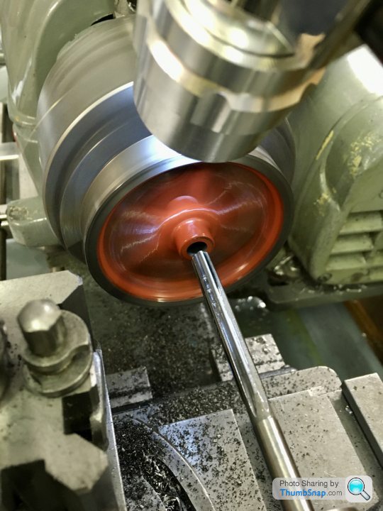
And machined the inside rim and boss, then reversed in the chuck and did the other side.
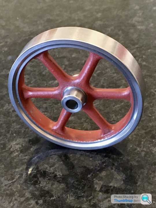
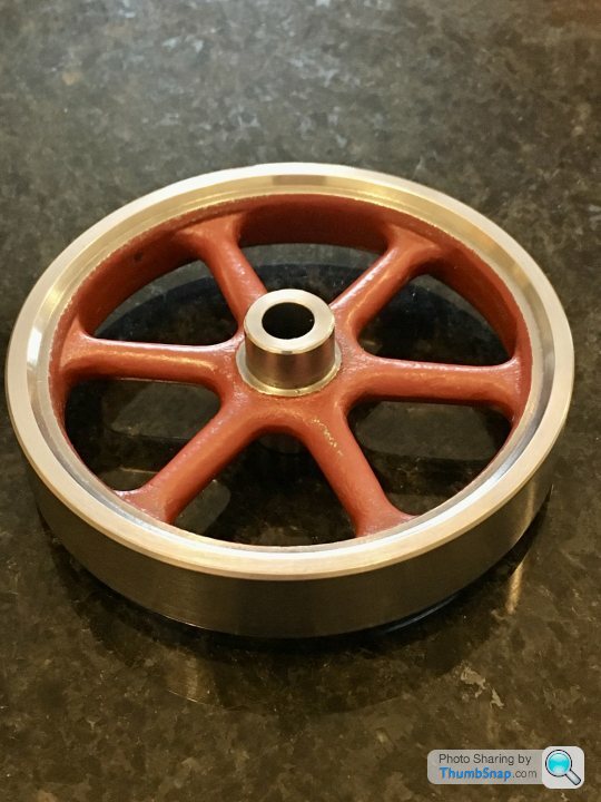
Fit on the shaft is fine, and the features turned on the initial setup are true, however the features on the reverse setup are noticeably off (when spun on the shaft). I might set it up again in the 4-jaw (on the o/d) and re-do the bits that are off.
Expanded the 3-jaw Chuck to clamp the inside of the rim, and turned true:
Drilled the bore:
Reamed to suit the crankshaft:
And machined the inside rim and boss, then reversed in the chuck and did the other side.
Fit on the shaft is fine, and the features turned on the initial setup are true, however the features on the reverse setup are noticeably off (when spun on the shaft). I might set it up again in the 4-jaw (on the o/d) and re-do the bits that are off.
Quick bit of turning to get back into it: The valve rod packing nut. It’s turned from some hexagonal bar:
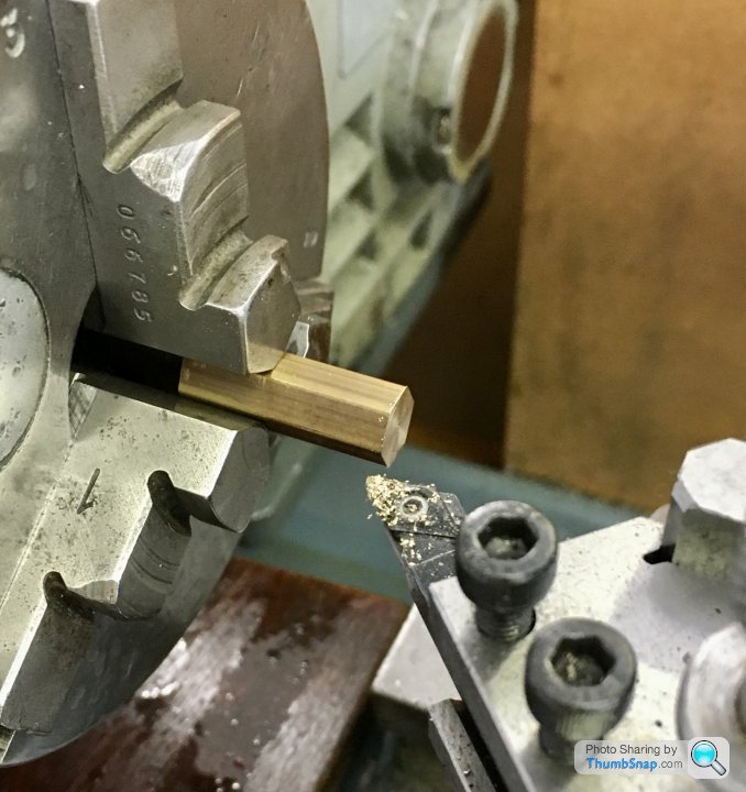
Then drilled and reamed to 1/8” to suit the valve rod.
Turned to 1/4” and chamfered to give a lead for the die:
Then chamfered the flats and parted off:
Seems to fit ok:
h
Then drilled and reamed to 1/8” to suit the valve rod.
Turned to 1/4” and chamfered to give a lead for the die:
Then chamfered the flats and parted off:
Seems to fit ok:
h
Edited by dr_gn on Sunday 19th July 19:21
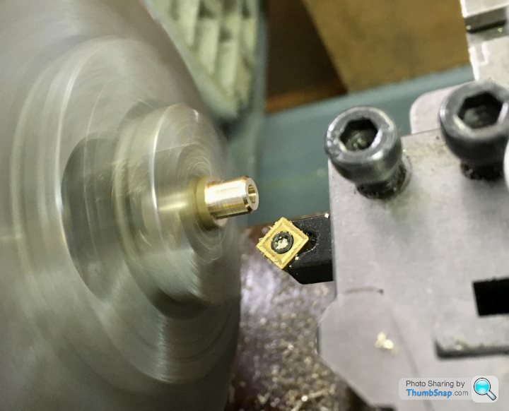
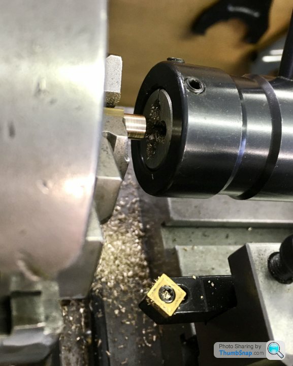
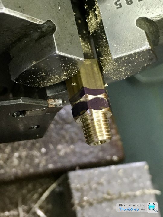
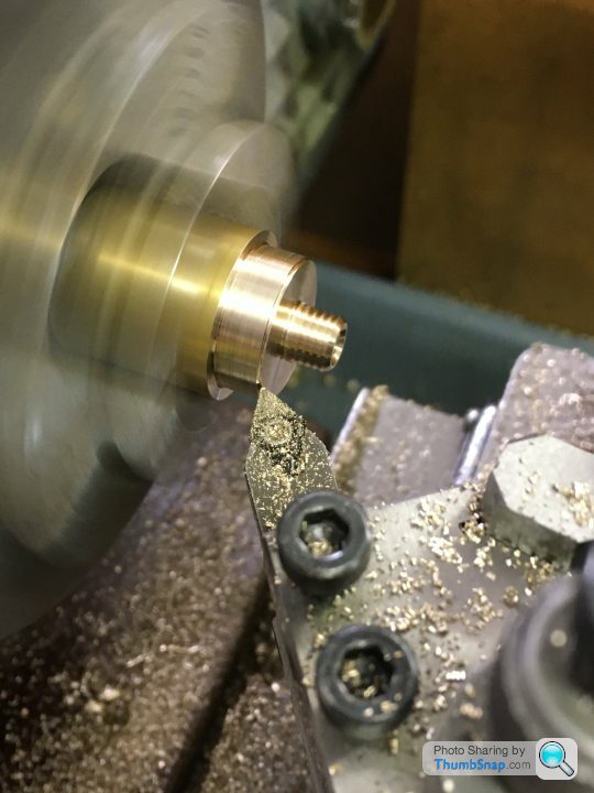
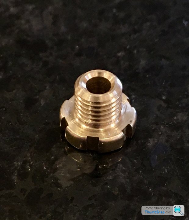
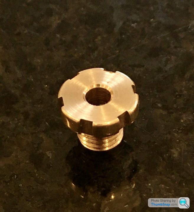
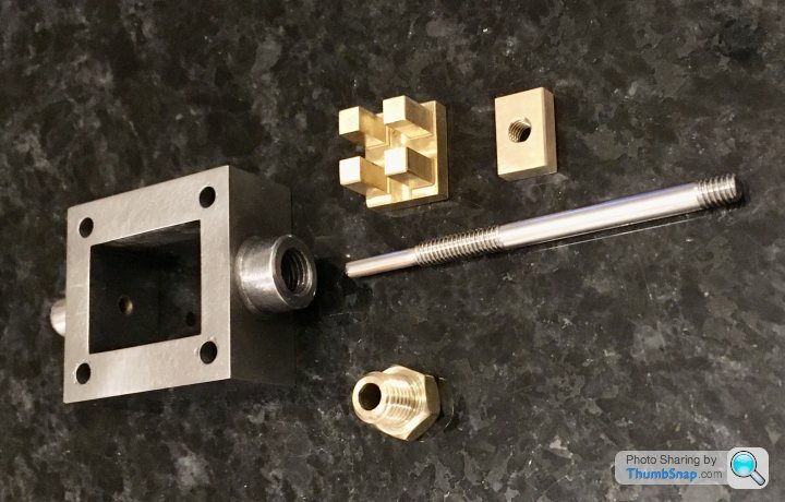
The piston rod seal packing nut is a bit different from the valve rod nut; it’s larger, and has screwdriver cut-outs for tightening instead of flats due to it fitting within the standard. It’s turned from the same brass stock suppled for the piston:
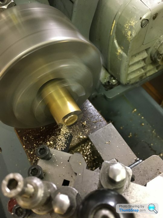
Drilled, reamed, threaded, then turned down to size before parting off:
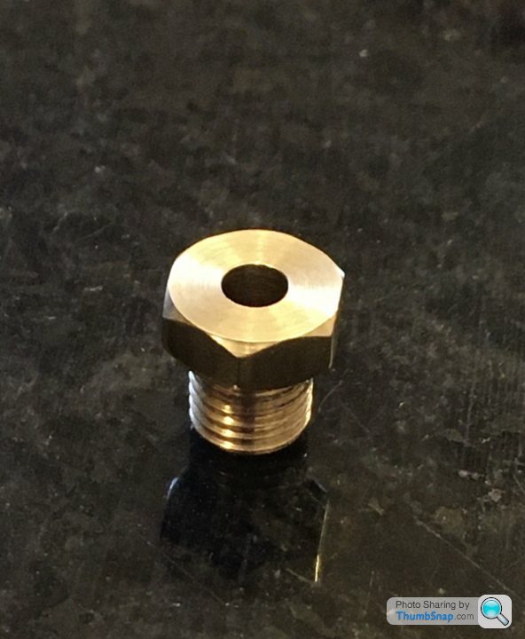
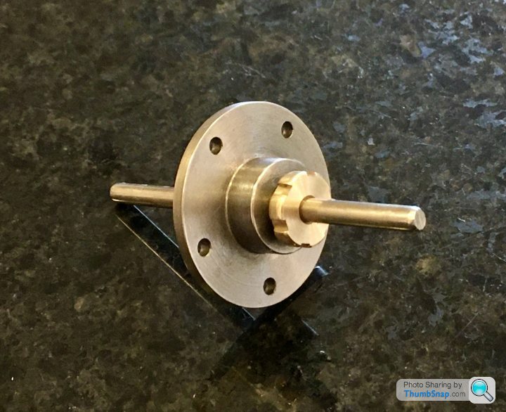
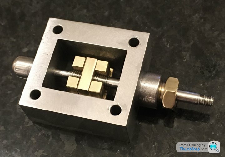
There are six undimensioned cut-outs in the O/D. I don’t have a rotary table, so I made a simple fixture out of the remaining hexaganol stock from the valve nut:
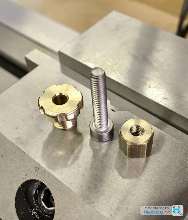
It’s just sits in the milling vice on a parallel, and the slots milled to 2mm and 0.85mm deep from touching on the diameter. Then move around one flat at a time:
Worked OK:
The threads are a bit sloppy in their holes, not sure why. I suppose I could use thread lock if they loosen.
Drilled, reamed, threaded, then turned down to size before parting off:
There are six undimensioned cut-outs in the O/D. I don’t have a rotary table, so I made a simple fixture out of the remaining hexaganol stock from the valve nut:
It’s just sits in the milling vice on a parallel, and the slots milled to 2mm and 0.85mm deep from touching on the diameter. Then move around one flat at a time:
Worked OK:
The threads are a bit sloppy in their holes, not sure why. I suppose I could use thread lock if they loosen.
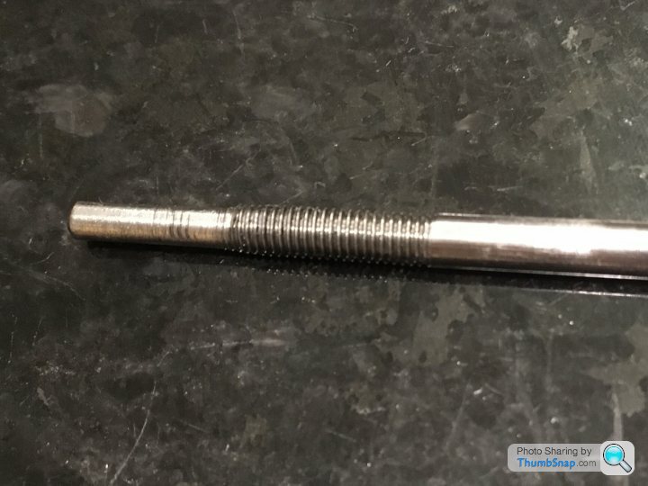
So here - somewhat inevitably - is where it goes wrong...
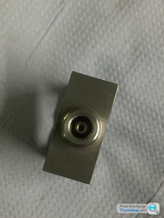
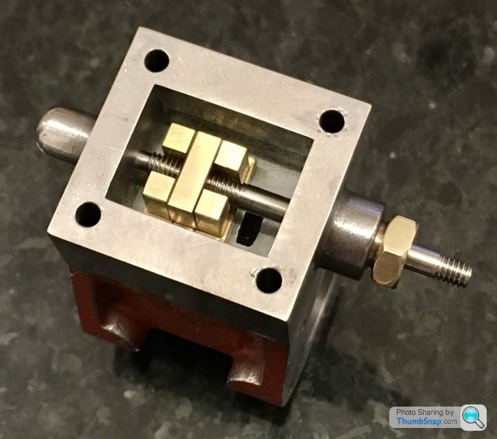
The valve rod is stepped, and threaded. First of all I made a split bush to fit the 3-jaw chuck (4-jaw won’t close enough). I got it to within 0.0015” of true, centre drilled and turned the end to be a good fit in the valve chest top as per the image:
Not sure if this was the best method, but I didn’t get a particularly good finish on the end. Still, it fitted smoothly enough.
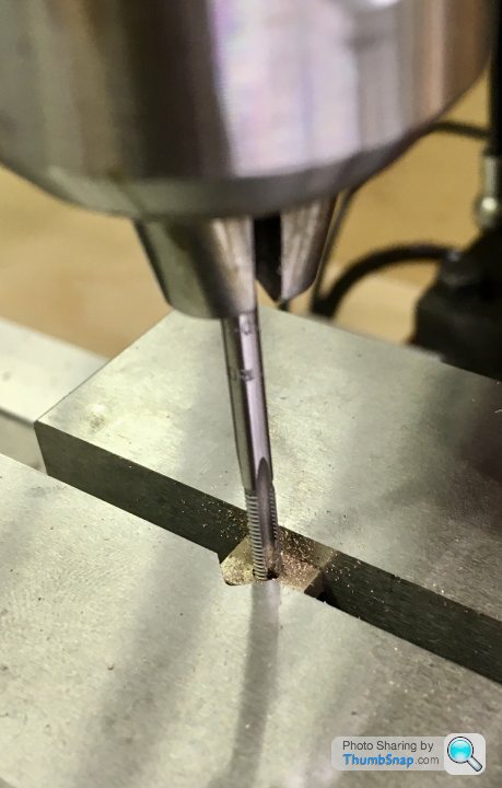
Then, the 5BA thread. The die wouldn’t go on the turned-down end. This is where my heart sank as I realised what I’d done. The hole in the top of the valve chest should be 3/32” (2.38mm), but for some reason I’d ended up with 2.75mm.
The root diameter of the 5BA tap is 2.49mm. so obviously it won’t go on.
M3 has a root diameter of 2.46mm (too small) and a slightly finer pitch Than 5BA. I had an old M3 die which did For whatever reason fit over the spigot, but the thread was all over the place. A new M3 die wouldn’t fit at all. The rod also got slightly bent during all this. It does fit, and it does slide in the chest, but it’s not right - too sloppy.
So...I don’t want to re-make another valve chest because it fits everything else perfectly. The only option I can see is to drill the top chest hole out to 1/8” (same as the reamed gland hole at the bottom), Loctite a brass plug into it and re-drill to 3/32”.
And of course re-make the rod.
The valve rod is stepped, and threaded. First of all I made a split bush to fit the 3-jaw chuck (4-jaw won’t close enough). I got it to within 0.0015” of true, centre drilled and turned the end to be a good fit in the valve chest top as per the image:
Not sure if this was the best method, but I didn’t get a particularly good finish on the end. Still, it fitted smoothly enough.
Then, the 5BA thread. The die wouldn’t go on the turned-down end. This is where my heart sank as I realised what I’d done. The hole in the top of the valve chest should be 3/32” (2.38mm), but for some reason I’d ended up with 2.75mm.
The root diameter of the 5BA tap is 2.49mm. so obviously it won’t go on.
M3 has a root diameter of 2.46mm (too small) and a slightly finer pitch Than 5BA. I had an old M3 die which did For whatever reason fit over the spigot, but the thread was all over the place. A new M3 die wouldn’t fit at all. The rod also got slightly bent during all this. It does fit, and it does slide in the chest, but it’s not right - too sloppy.
So...I don’t want to re-make another valve chest because it fits everything else perfectly. The only option I can see is to drill the top chest hole out to 1/8” (same as the reamed gland hole at the bottom), Loctite a brass plug into it and re-drill to 3/32”.
And of course re-make the rod.
Thanks, yep, I think that’s the answer. I’ve asked on the ME forum too, but there can’t be many options.
Not making excuses at all, but I think part of the issue was/is the drawings. They only have basic, un-toleranced dimensions, and the Stuart book I’ve got rounds imperial to metric, often to whole numbers. I’ve got into a habit of thinking “so long as that fits to that nicely, the absolute numbers don’t matter too much”. I totally missed the root diameter being critical.
I think I’ll clean the workshop up, get everything back in it’s place and try again. I was hoping not to have to buy any replacement parts, but I think the rod is too short now.
When I asked the question, the answer was "Loctite 638" which is a high strength fast cure fluid for basically exactly this, and available in 10ml qty.
The job I was doing was asking a stupid amount of the adhesive so I also bought a can of Loctite 7061 super clean in the hope the part knew I had doubled the cost for it. It held for a year and then I had a friend with a milling machine add some mechanical retention!
In 2016 you could get the lot from Bearing King for £25 with next day delivery.... else use whatever you have in stock and it will likely be fine!
Daniel
I've got some high strength retainer, so if it's a tight fit it won't go anywhere. Question is wall thickness and being able to drill it perfectly concentric.
The comment form the ME forum was to partially thread the spigot becasue it won't have any effect on the function of the part. I can't assemble it like that though...
The comment form the ME forum was to partially thread the spigot becasue it won't have any effect on the function of the part. I can't assemble it like that though...
So I tried to find a sleeve of about the right size, but no luck. I also considered making a Pre-drilled bush to press in, and drill to size when fitted, but a) A small enough drill was very flexible and b) The very thin wall might collapse on fitting.
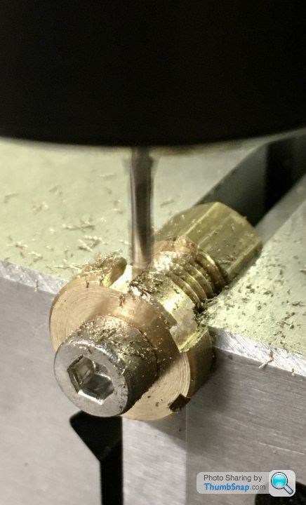
Anyway I fitted a plain brass plug:
Set it up as best I could again in the 4-jaw chuck and re-drilled to a size that was a definite clearance fit in the 5BA die:
OK, ok it’s not drilled exactly centrally, but there we go. I guess there was no guarantee the initial hole was spot-on either.
There is some float in the lower seal hole and nut, so I think the new valve rod (yet to re-make it) should be a good enough fit. If not I’ll drill out again and risk a pre-centred bush.
Anyway, lessons learned. Onwards...
dr-gn
Myford and DRO
Got mine from Machine DRO, i did have some like yours on my WarcoWM16 but wasnt happy with them,
The M-DRO are a revalation if you get the Essien( need to check on the name) it even works out PCD and hole centres!!!
That one reads out to .0002 and the Lather one goes down to 0.00010
However this cured ,or i thought it did, the backlash, no more faffing about with watching the micro dial etc. BUT i was still getting duff measurements even though the digital read out was ok ,UNTIL one day noticed that the top slide had some play of about 10 thous Ahhh backlash, but no,after checking various bit it was a worn thread. got replacement from Myfords and now all is well again in the shed!
So tip to all check the worm and nut, it could be the best 100.00 you spend
silverfoxcc said:
dr-gn
Myford and DRO
Got mine from Machine DRO, i did have some like yours on my WarcoWM16 but wasnt happy with them,
The M-DRO are a revalation if you get the Essien( need to check on the name) it even works out PCD and hole centres!!!
That one reads out to .0002 and the Lather one goes down to 0.00010
However this cured ,or i thought it did, the backlash, no more faffing about with watching the micro dial etc. BUT i was still getting duff measurements even though the digital read out was ok ,UNTIL one day noticed that the top slide had some play of about 10 thous Ahhh backlash, but no,after checking various bit it was a worn thread. got replacement from Myfords and now all is well again in the shed!
So tip to all check the worm and nut, it could be the best 100.00 you spend
Thanks for that. Big question is cost. TBH the cheap scales I put on the mill have been great so far. I don't expect them to last forever, but there's no doubt that I couldn't have got this far with the build without them.Myford and DRO
Got mine from Machine DRO, i did have some like yours on my WarcoWM16 but wasnt happy with them,
The M-DRO are a revalation if you get the Essien( need to check on the name) it even works out PCD and hole centres!!!
That one reads out to .0002 and the Lather one goes down to 0.00010
However this cured ,or i thought it did, the backlash, no more faffing about with watching the micro dial etc. BUT i was still getting duff measurements even though the digital read out was ok ,UNTIL one day noticed that the top slide had some play of about 10 thous Ahhh backlash, but no,after checking various bit it was a worn thread. got replacement from Myfords and now all is well again in the shed!
So tip to all check the worm and nut, it could be the best 100.00 you spend
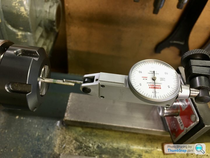
So tonight I re-set the scrap valve rod in the lathe and sawed the threaded end off. I found that putting it in a collet gave me 0.0015” runout, so I stuck with that rather than messing about with the split bush and 3-jaw chuck:
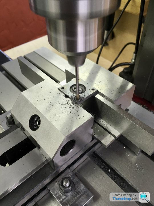
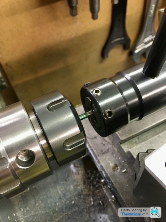
Centre drilled, and turned down to size with a DCGT insert, then tried the 5BA die. This time it worked. I needed to turn a pointed grub screw to open the die though:
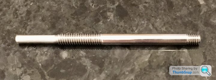
There was about 1mm to spare. Flushed with success, I milled the valve plate to size:
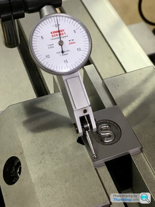
And drilled and tapped it after centering using the edge finder:
Fit in the rod was spot-on.
So then onto cleaning-up the valve Itself and the rest of the parts. The fit of the rod in the chest is pretty good, if a bit sticky at the top of the travel, but only in one orientation. Might need a bit of lapping or something to get it perfect. I think it’s Probably fine as it is though.
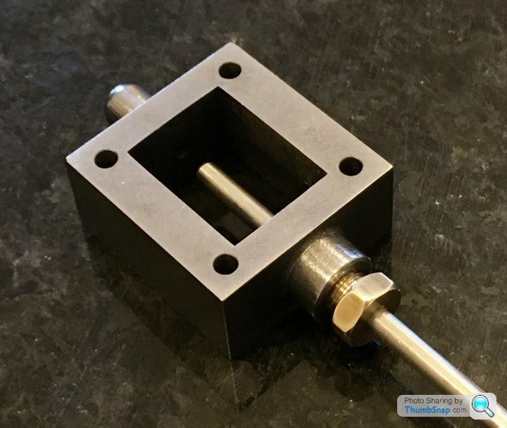
All seems to fit together well:
And I think the travel is OK for the ports too:
Just need to make sure the eccentric throw is spot-on.
Centre drilled, and turned down to size with a DCGT insert, then tried the 5BA die. This time it worked. I needed to turn a pointed grub screw to open the die though:
There was about 1mm to spare. Flushed with success, I milled the valve plate to size:
And drilled and tapped it after centering using the edge finder:
Fit in the rod was spot-on.
So then onto cleaning-up the valve Itself and the rest of the parts. The fit of the rod in the chest is pretty good, if a bit sticky at the top of the travel, but only in one orientation. Might need a bit of lapping or something to get it perfect. I think it’s Probably fine as it is though.
All seems to fit together well:
And I think the travel is OK for the ports too:
Just need to make sure the eccentric throw is spot-on.
dr-gn
I agree with the cost side, BUT since having them fitted on the 7 and the WM16 the scrap box is looking a lot emptier!! In fact my son often said i had enough bits in there to make another three engines!!
I did start off with the kit you have got, but when i saw the MDRO set up i was smitten!! start saving, you will not regret it
silverfoxcc said:
dr-gn
I agree with the cost side, BUT since having them fitted on the 7 and the WM16 the scrap box is looking a lot emptier!! In fact my son often said i had enough bits in there to make another three engines!!
I did start off with the kit you have got, but when i saw the MDRO set up i was smitten!! start saving, you will not regret it
OK I'll look into it. I'm planning on building a Sturat Twin Victoria and Beam engine after the 10V. That should scratch the model engineering itch.I agree with the cost side, BUT since having them fitted on the 7 and the WM16 the scrap box is looking a lot emptier!! In fact my son often said i had enough bits in there to make another three engines!!
I did start off with the kit you have got, but when i saw the MDRO set up i was smitten!! start saving, you will not regret it
dr-gn
Here are a couple of pics of the screens you get
First is the MDRO ML7 you can jst see the reader for the cross slide ( you do have to mill out a slot in the underside of the crossslide, but doesn't affect the slldeways
you will see it reads down to 0.00001
The ABS R is in the radius mode, you can also set it to work out the diameters
Also you can set it so when you change tools you tap in the one you are now using and it compensates for the differences in the X and Z axis
The second and third pics are of the Easson kit for the WM16. although it can be used on other makes I used the holes i had drilled already for the 'basic' readers that you have
Edited by silverfoxcc on Saturday 25th July 18:29
Edited by silverfoxcc on Saturday 25th July 18:31
Edited by silverfoxcc on Saturday 25th July 18:32


Gassing Station | Scale Models | Top of Page | What's New | My Stuff