Schumacher CAT XLS build
Discussion


Steering link didn’t stay in the packet long. After a nightmare of a day with kids that want to be anywhere but at home and trying to work from home whilst dealing with them it was great to sit and tinker for an hour.
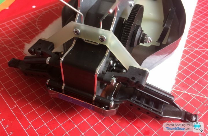
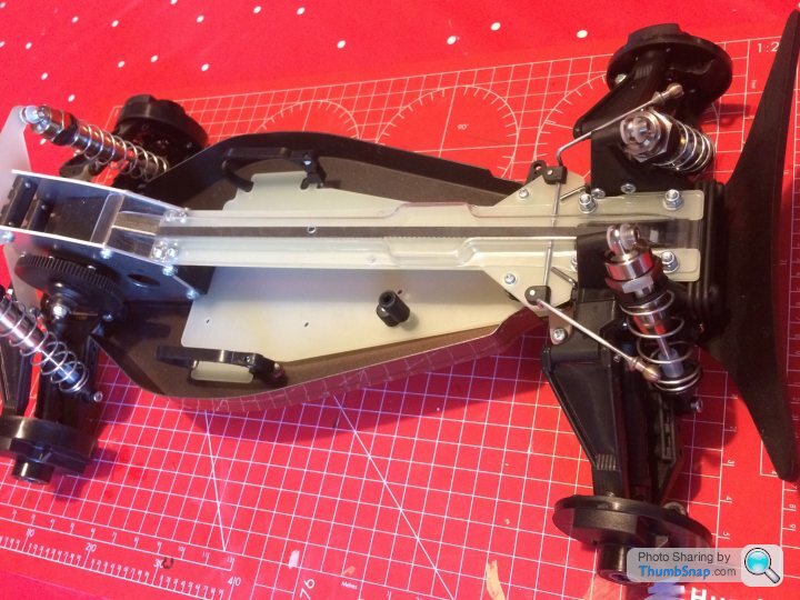
Built the rear wing mount, the brackets for the upper wishbones needed a little bit of cleaning up but go together nicely.

After that I tackled the steering linkage. This took a little while as the arms are slightly thicker than the brass bushes so if built as supplied it binds when you nip the screws up. Carefully removed some material until the bushes were just proud of the arms and now it all moves smoothly but with no play. Lots of tiny washers to get in the right places and small bits which have to be threadlocked on. Satisfying when it’s all together and working well though.

Built the rear wing mount, the brackets for the upper wishbones needed a little bit of cleaning up but go together nicely.
After that I tackled the steering linkage. This took a little while as the arms are slightly thicker than the brass bushes so if built as supplied it binds when you nip the screws up. Carefully removed some material until the bushes were just proud of the arms and now it all moves smoothly but with no play. Lots of tiny washers to get in the right places and small bits which have to be threadlocked on. Satisfying when it’s all together and working well though.
Sprayed the undertray tonight, I realise this was probably a waste of time as it will get scratched to hell in use but I enjoyed it and wanted to see how the colours worked together before I decide on the colour scheme for the bodyshell. Love peeling off the masking to reveal shiny underneath!

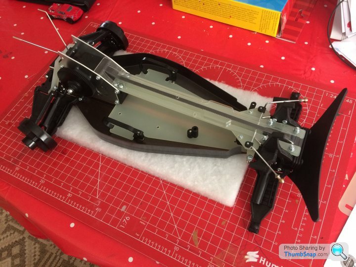
one Of the he kids was up early so took the opportunity to ream out all the holes in the undertray and screw it on, along with the front bumper and crashback pivot blocks. Everything lined up nicely, put the screws in one at a time to hold things in line, then squeezed the decks together to hold it in place while I put the bumper on. Feels nice and solid now. Next step is to tension the belts. Any tips?

Thanks that worked well  could’ve done with another hand to keep the front belt taught while nipping the screws up though!
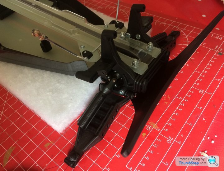
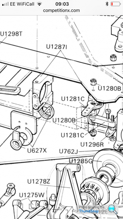
Pretty much plain sailing to the end now, rear transmission cover and lower wishbones in place. Need to find a suitable spanner to tighten the bits on the long stud through the upper wishbone brackets as there’s not enough space to get a socket on. Might replace it with a long bolt and a nyloc.
Got the crashback system and lower wishbones on the front too, bit of a fiddle getting the pivot pins through
could’ve done with another hand to keep the front belt taught while nipping the screws up though!Pretty much plain sailing to the end now, rear transmission cover and lower wishbones in place. Need to find a suitable spanner to tighten the bits on the long stud through the upper wishbone brackets as there’s not enough space to get a socket on. Might replace it with a long bolt and a nyloc.
Got the crashback system and lower wishbones on the front too, bit of a fiddle getting the pivot pins through
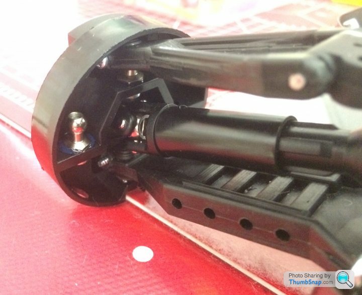
Been looking at the suspension arms and rear hub carriers. Unusual design but quite clever in that it uses the same part for each side, cheaper mould tool and one less spare to carry.
I deviated from the instructions slightly and found it was easier to assemble the hub carrier to the lower wishbones before putting the driveshaft in, as the UJ was getting in the way of the ball joint. Once in place a screw is inserted into the wishbone to lock the ball in place similar to 1:1 cars I’ve worked on.
Suspension is remarkably smooth and slop free in operation, puts tamiya to shame.
Rear shocks last night. These are lovely machined aluminium and have a brass insert at the bottom to support the shock shaft and house the seal pack:
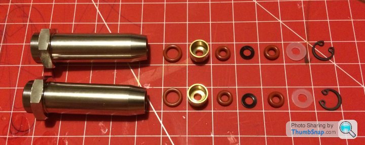
That lot is held in with a tiny circlip, hence the need for the circlip pliers mentioned above. Goes together pretty easily when you have the right tools!
The shock pistons are hen built up with the shaft, nice fiddly e-clips, managed to not ping any accross the room:
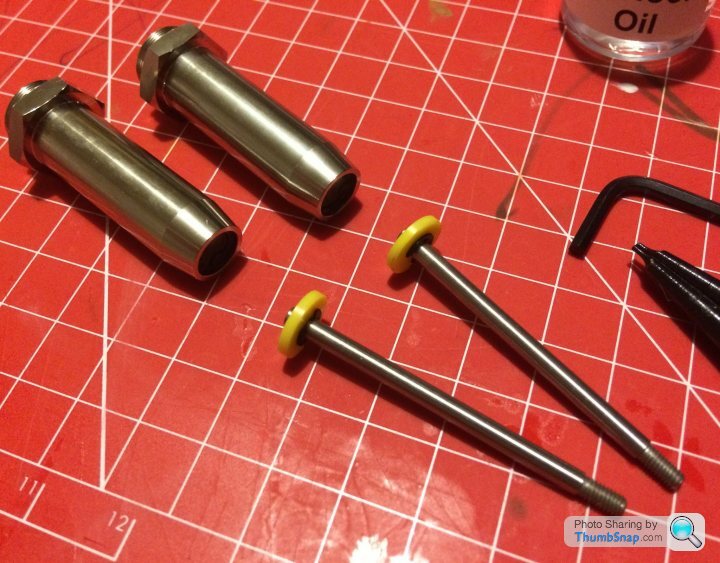
Then it’s just a case of cutting the bump stops to length and filling with oil, getting the bubbles out and fitting the gland and top cap on. Lovely little assemblies that really stand out
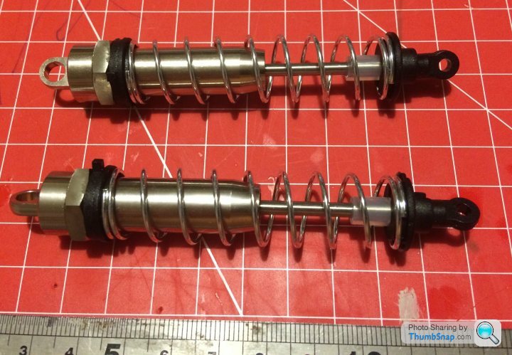
Then they are fitted to the chassis with some nylon bushes taking care to ensure they are not binding but don’t have any slop
That lot is held in with a tiny circlip, hence the need for the circlip pliers mentioned above. Goes together pretty easily when you have the right tools!
The shock pistons are hen built up with the shaft, nice fiddly e-clips, managed to not ping any accross the room:
Then it’s just a case of cutting the bump stops to length and filling with oil, getting the bubbles out and fitting the gland and top cap on. Lovely little assemblies that really stand out
Then they are fitted to the chassis with some nylon bushes taking care to ensure they are not binding but don’t have any slop
Thanks for the tip, have done the front suspension last night so the turnbuckles are next on the list. I vaguely remember doing that on my SST axis touring car but had completely forgotten about it! It’s just the track rods on this as the upper arms are fixed length.
Edited by lufbramatt on Friday 22 May 16:47
If I feel the need for adjustable upper arms I'll either make something from acetal on the milling machine at work (assuming I ever get back to the office!) or CAD something up and get my friendly prototyping guy to 3D print it in a suitable material. The turnbuckles and ball sockets are pretty cheap.
Turnbuckles on and roughly adjusted. Was a bit confused as the manual says to set the front track rod arms to 38mm but doing this resulted in a huge amount of toe in, then I remembered I had fitted the wide track steering link which is longer than the kit part so the track rods have to be shorter :-)
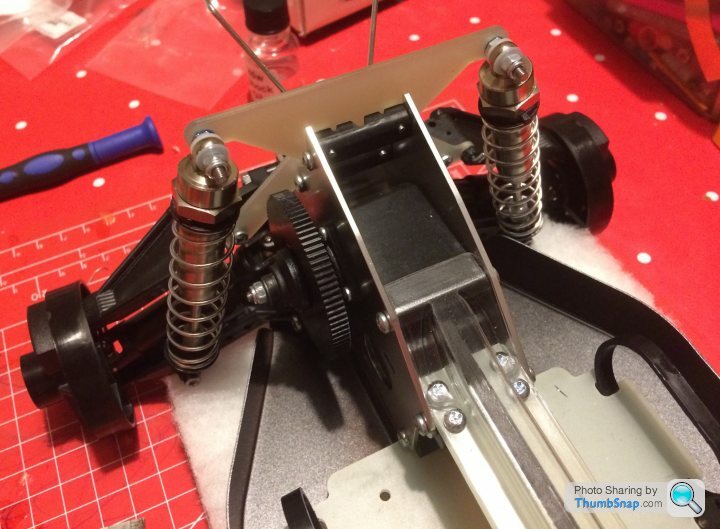
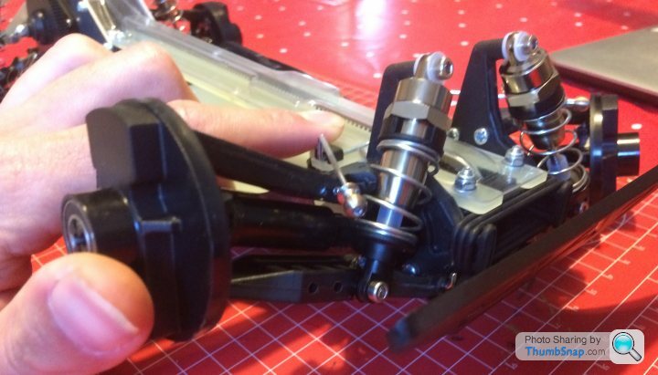
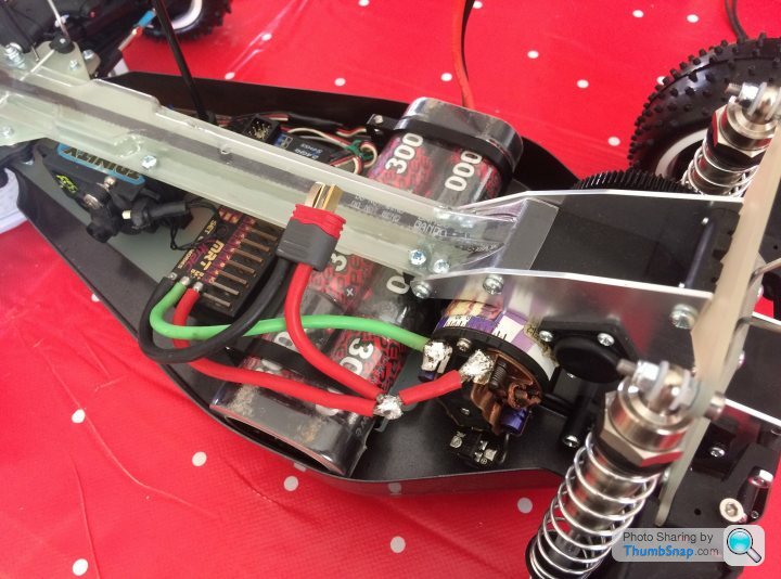
Came accross this issue though when I put the servo mounts in, the right hand brace that links the top and bottom decks is exactly where the wires come out of my servo. (Look where the silver screw is) I can either space the servo over to the left by putting washers between the servo and the posts or leave out the brace. Thoughts?

Came accross this issue though when I put the servo mounts in, the right hand brace that links the top and bottom decks is exactly where the wires come out of my servo. (Look where the silver screw is) I can either space the servo over to the left by putting washers between the servo and the posts or leave out the brace. Thoughts?
Soldering iron out last night, electronics all in, getting closer to finishing 
Need to replace all the tamiya plugs on our batteries with deans. Servo choke wired up to esc, and battery/motor cables re done to fit the cat chassis layout better. Schottky diode and motor suppressor caps fitted too. Still need to tidy up the signal wires from the receiver to servo and esc and wrap some self amalgamating tape around the joint in the red wire but ran out of evening.
Just waiting on a different servo saver (kit one is 25 spline, I need a 23 spline for the KO servo) then I can go for a test drive!
Edited by lufbramatt on Tuesday 26th May 09:34
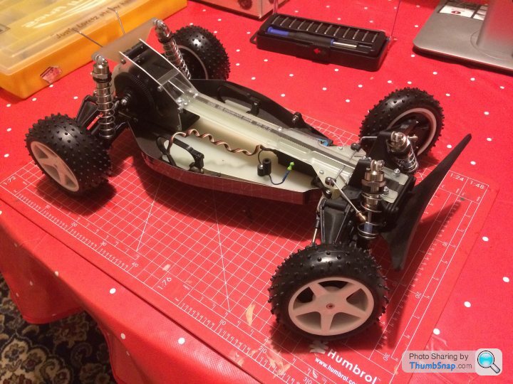
Got the correct servo saver eventually through the post so finished the rolling chassis tonight and had a quick buzz round the garden :-)
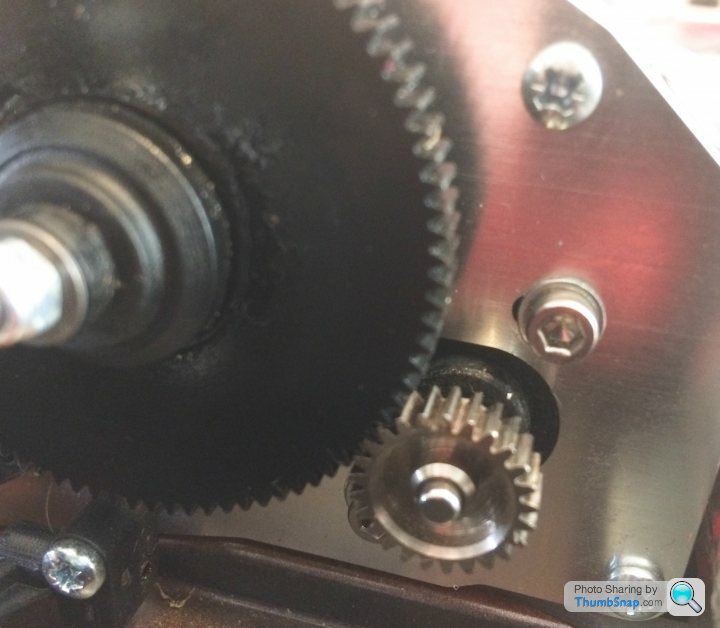
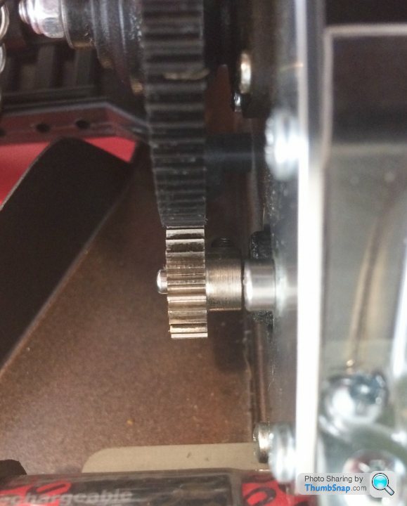
Drives ok but it seems really noisy? Seems to be a whining noise coming from the spur gear. Belts don't seem to be slipping. Are they all like this or have I done something wrong- gear mesh too loose/tight?
Pinion is a 25t that I had on my SST axis touring car which appears to use the same 48dp tooth pitch as the re-re CAT.
Thanks Nigel- Nail on the head with your first comment! I had been an idiot and managed to pick up a Tamiya pinion from my TA-03 instead of the Schumacher pinion! Very similar pitch but slightly different. Not run it again but feels instantly better rotating things by hand.
I only ran it for about 20 seconds earlier as it was obvious something wasn't right so don't think I've damaged anything.
I only ran it for about 20 seconds earlier as it was obvious something wasn't right so don't think I've damaged anything.

Spent last night soldering Deans connectors on to all our batteries and charger leads, so was able to give the CAT a proper run in the garden today.
Transmission is nice and quiet, happy with that now.
It's a bit pointy compared to my lads 2wd Racing Fighter! don't have to use the brakes to get it to turn in. Full brakes with steering lock will get the back to step out. I know what people mean now when they say the old CATs were fast but tricky to get the best out of.
It's suprizingly quick, even with the brushed motor in, will wheelspin all 4 wheels about 2m up the garden, great fun seeing the back squat down. Does nice drifts too where the lawn is a bit worn out (kids playing in the garden every day during lockdown!). Not sure what the top speed is like as the garden isn't big enough!
Next step is to get the wing and shell cut out and painted.
Gassing Station | Scale Models | Top of Page | What's New | My Stuff