Paper Ship: Bismarck, HMV, 1:250
Discussion


Squirrelofwoe said:
dr_gn said:
lufbramatt said:
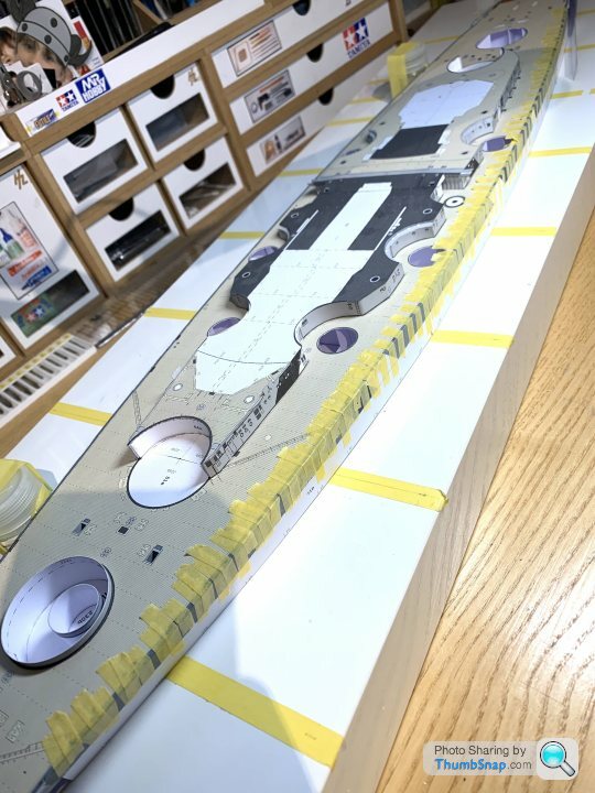
The sheer size of this has just dawned on me- one of my colleagues bought a Tamiya 1:350 Yamato last week and that’s massive, this is way bigger!
I can’t begin to fathom how you have he patience to see these builds through!
Yes it’s a bit on the large size - just over 1m. I’ve put an Ikea shelf up to keep it on just for this build.I can’t begin to fathom how you have he patience to see these builds through!
Someone I know has the Tamiya 1:350 Bismarck, this one is infinitely more detailed. Unfortunately all that detail has to be cut out, folded up and glued together...
Edited by dr_gn on Thursday 16th January 21:56

I am a patient person, but something like this would break me just cutting out all of the parts...

El stovey said:
https://play.acast.com/s/dansnowshistoryhit/f78365...
There’s a great BBC history hit podcast by Dan Snow about hunting the Bismarck just out, I was listening to this morning that I thought might be good to listen to Dr.
I think it’s the second one in.
His podcasts are pretty good if anyone’s interested.
Thanks very much - I'll have a listen this weekend.There’s a great BBC history hit podcast by Dan Snow about hunting the Bismarck just out, I was listening to this morning that I thought might be good to listen to Dr.
I think it’s the second one in.
His podcasts are pretty good if anyone’s interested.
archie456 said:
dr_gn said:
Turn7 said:
Is UHU still the hideous stringy, gets everywhere stuff I remember from my childhood ?
Yes, it’s absolutely hopeless to work with on anything more critical than large bits of model which will never be seen again.It certainly does the job when used in the right places though.
ferrisbueller said:
This had dropped off my watchlist for some reason so I've only just caught up on the tragic events of January. Heartened to see another one underway and racing to a finish.
Amazing work, as per.
Wouldn’t say “racing”! Amazing work, as per.
I looked at it again on Thursday evening, and immediately ran into an unfathomable assembly on the first bit of superstructure...
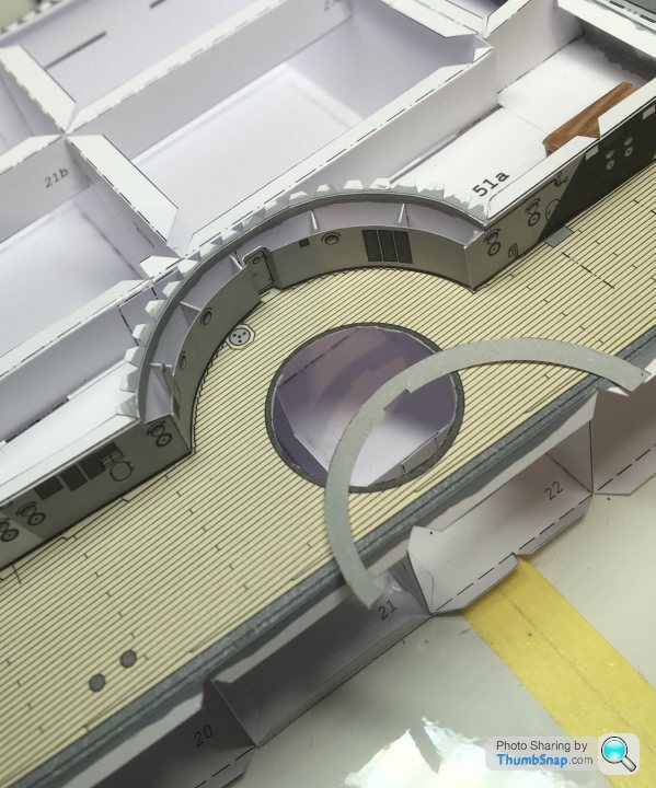
That prompted me to get on with it today. I’ve 90% figured out the area between the two main superstructure blocks. It’s a complex assembly of faceted plates and cantilevered overhangs that somehow form a roof over the gap, with the catapult off to one side:
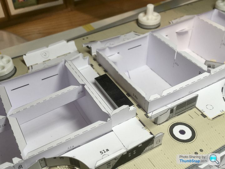
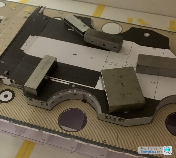
Here are some of the parts:
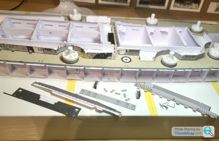
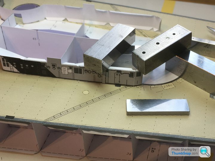
I’ve cut some of the more complicated z-folds out of their original parts - makes alignment easier. Also painted the exposed edges, and used the first bits of laser-cut card: bulkhead stiffeners.
Here are some of the parts:
I’ve cut some of the more complicated z-folds out of their original parts - makes alignment easier. Also painted the exposed edges, and used the first bits of laser-cut card: bulkhead stiffeners.
Here’s a fairly typical problem with tolerance stacks and paper models: the first piece of the superstructure wall needs to fit exactly on its footprint on the deck, butt up to the catapult trough, and match up with a curved piece, which is itself part of an assembly. All need to match precisely with the roof of the superstructure , which is one piece, so can’t easily be adjusted:
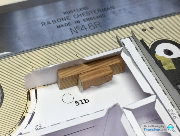
Trouble is, the superstructure wall piece is about 1mm too far back, so won’t match the curved piece. This will throw the whole lot out. I’ve glued a wood strip to the back of the wall, and another to the deck. I’m hoping to put some glue on the mating faces and force the wall forward slightly until the glue sets.
Trouble is, the superstructure wall piece is about 1mm too far back, so won’t match the curved piece. This will throw the whole lot out. I’ve glued a wood strip to the back of the wall, and another to the deck. I’m hoping to put some glue on the mating faces and force the wall forward slightly until the glue sets.
I’ve replaced the horizontal tabs of the decks with doubled paper pva’d into their slots. Their absence made deck fitting easier, but the structure lost a bit of stiffness. All back now. Now adding the first superstructure sides, inch-by-inch:
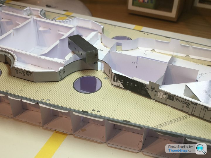
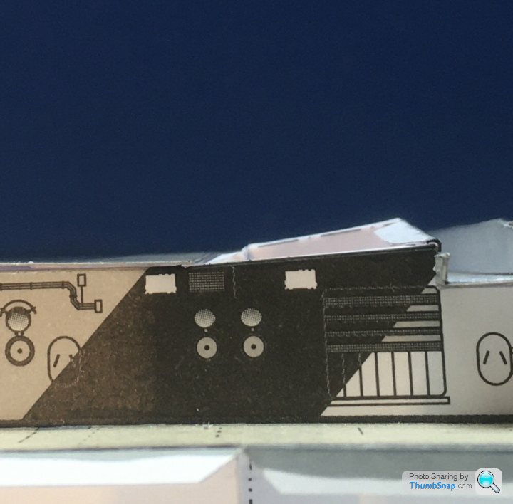
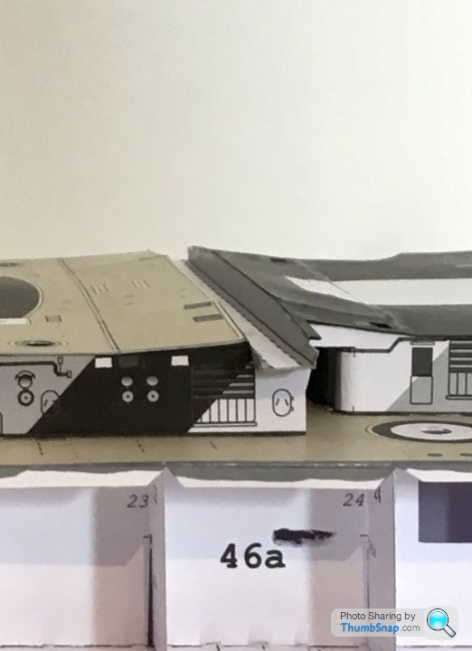
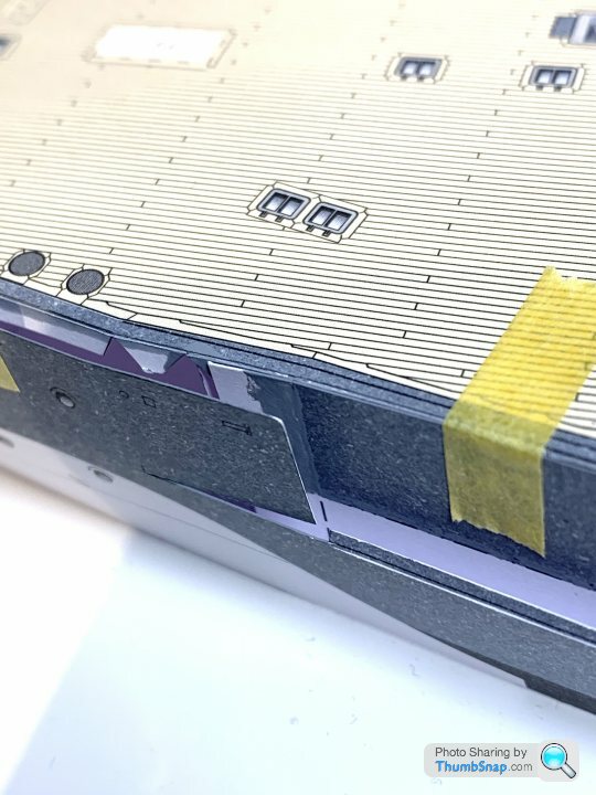
Alignment with the next deck is all over the place (see the door between the metal blocks, and how it’s deck plate is offset), but that’s how it goes with paper models of this complexity...
Also, part numbering can be hit and miss, which can get confusing:
Should be part 65B.
Alignment with the next deck is all over the place (see the door between the metal blocks, and how it’s deck plate is offset), but that’s how it goes with paper models of this complexity...
Also, part numbering can be hit and miss, which can get confusing:
Should be part 65B.
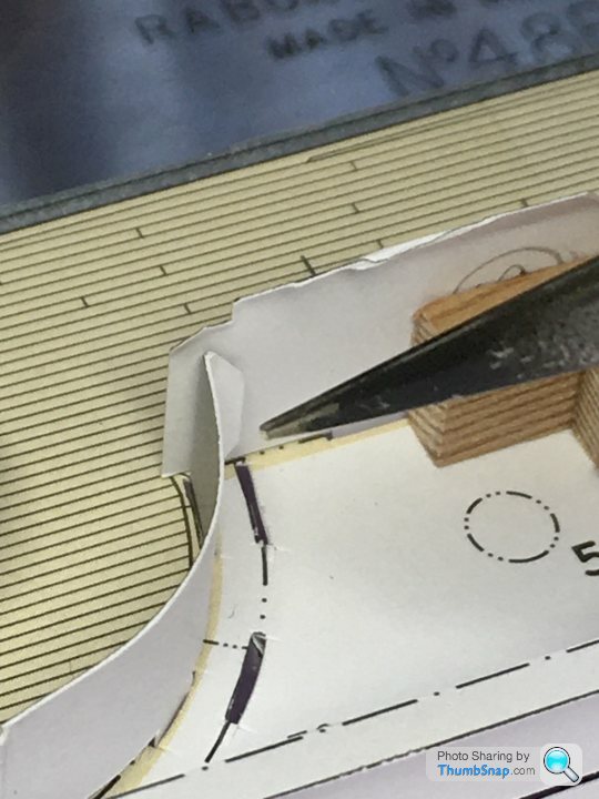
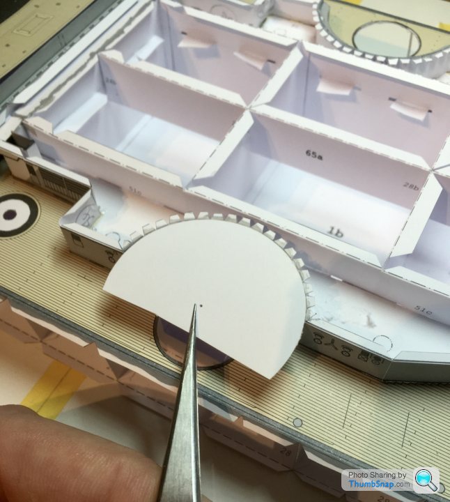
First of the upper decks: Not too bad a fit, but some slight overhangs, especially in the secondary turret circular cut-outs. I cut a template disc with the Olfa circle cutter, and got it to be a perfect fit in the curve:
Then used the female part of the template to mark the underside of the deck, as a trimming guide:
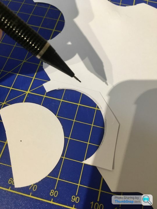
Still fettling to do, but it’ll hopefully be a big improvement:
Then used the female part of the template to mark the underside of the deck, as a trimming guide:
Still fettling to do, but it’ll hopefully be a big improvement:


As predicted, the catapult trough area has been tricky; it’s an odd combination of angled decks, that don’t seem to have enough score lines to define the surfaces accurately. Reference images show it as a kind of impossible blended form:

I ended up cutting the adjacent decks, adding additional score lines, and trimming everything to suit:


The end result - I guess must be sort of what the model designer intended:

I might try to neaten up the joints on the black areas - not my best work. The trough itself should have vertical sides, but they’ve ended up slopes. Not sure how, because any adjustment would mean the decks wouldn’t line up somewhere else. Luckily there’s a load of other stuff to fit in and around it:

I ended up cutting the adjacent decks, adding additional score lines, and trimming everything to suit:
The end result - I guess must be sort of what the model designer intended:
I might try to neaten up the joints on the black areas - not my best work. The trough itself should have vertical sides, but they’ve ended up slopes. Not sure how, because any adjustment would mean the decks wouldn’t line up somewhere else. Luckily there’s a load of other stuff to fit in and around it:
rolster said:
Hi there, I was wandering if there was any progress, with this one over the last few months of global crisis?
Hello, afraid not - I've been trying to progress a few other half finished builds. In the end, I've only suceeded in starting yet another model, but I also finished that one!I've found that switching from paper to plastic to metal to engineering models isn't easy.
Thought I’d bite the bullet with this one while waiting for airbrush spares for the Vulcan.
I remember now why I paused it (at the beginning of the first lockdown): The hull sides make or break a paper ship model, and this one is a monster. Multiple pieces to try to make invisible joins, doubled and tapered areas around the armour belt, and compound curves at the bow and stern:
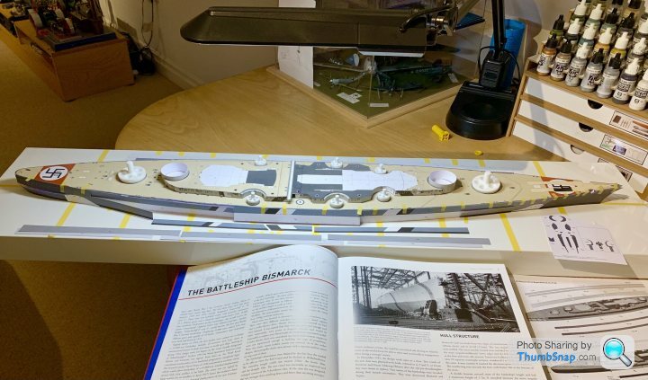


There are also two doubled joins towards either side of, and above the armour belt. None visible in photographs, which is odd for HMV to put steps there if it’s not realistic.
I remember now why I paused it (at the beginning of the first lockdown): The hull sides make or break a paper ship model, and this one is a monster. Multiple pieces to try to make invisible joins, doubled and tapered areas around the armour belt, and compound curves at the bow and stern:
There are also two doubled joins towards either side of, and above the armour belt. None visible in photographs, which is odd for HMV to put steps there if it’s not realistic.
I think I see what they’ve done. The armour belt forms a smooth curve along the waterline, but the upper hull cranks in, rather than the armour bulging out. The deck pieces have corresponding very slightly cranked sides to match. Makes more sense now, but still a bit of fettling to do:
rolster said:
Great to see this project resurected, if but for short time, until the Vulcan takes over again.
I’m enjoying both at the moment - makes a nice contrast in techniques. I’m hoping to make some progress on machining the steam engine as well this holiday (assuming it’s not too cold in the garage); then it’ll be all three modelling types I like: engineering, plastic and paper.Continuing with the hull sides. It’s a tricky stage on any paper ship build, made worse on this one by the sheer size of the parts, the compound curves and the number of joins. I’m aiming for joint line free, smooth surfaces.
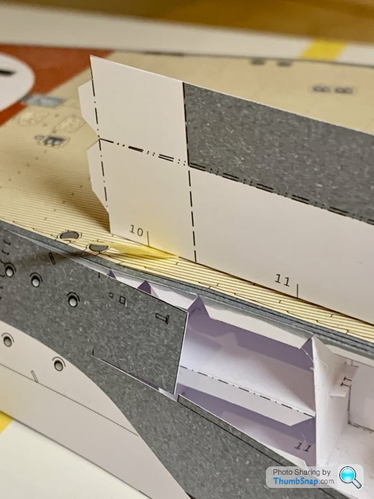
Anyway, I’m continuing to use the technique I’ve been experimenting with, to get almost invisible joins: once the lengths are confirmed, I cut the edges to be butted together at an angle; the angle must be greater than the chamfer of the blade:

Then temporarily tape them together, and run PVA along the “v” shaped interface (formed by the cut) on the back side, and double it up with printer paper. The result is this:

And this is the result if you use a perpendicular cut - the “v” is formed at the outside (corresponding pretty much to the chamfer angle of the blade) resulting in an unsightly line:

So I’ve painted the edges to get rid of the white highlights, and also painted over any dotted construction lines, again I think they don’t look good on a paper model. Now ready for fitting, and work continues on the bow and stern pieces, and the waterline armour belts:
One thing I noticed is that the stern camouflage chevrons seem wrong. The width of the black and the white areas are different on the hull and in the superstructure:

According to my reference book, they should be similar (this is the opposite side, so it’s a mirror image):

I think I read somewhere there was a colour error on this kit, perhaps this was it? Anyway, a bit of work with the airbrush should sort the widths out.
Anyway, I’m continuing to use the technique I’ve been experimenting with, to get almost invisible joins: once the lengths are confirmed, I cut the edges to be butted together at an angle; the angle must be greater than the chamfer of the blade:
Then temporarily tape them together, and run PVA along the “v” shaped interface (formed by the cut) on the back side, and double it up with printer paper. The result is this:
And this is the result if you use a perpendicular cut - the “v” is formed at the outside (corresponding pretty much to the chamfer angle of the blade) resulting in an unsightly line:
So I’ve painted the edges to get rid of the white highlights, and also painted over any dotted construction lines, again I think they don’t look good on a paper model. Now ready for fitting, and work continues on the bow and stern pieces, and the waterline armour belts:
One thing I noticed is that the stern camouflage chevrons seem wrong. The width of the black and the white areas are different on the hull and in the superstructure:
According to my reference book, they should be similar (this is the opposite side, so it’s a mirror image):
I think I read somewhere there was a colour error on this kit, perhaps this was it? Anyway, a bit of work with the airbrush should sort the widths out.
Got the stbd. mid sides on (the ones I made yesterday). Began by setting a datum in the middle:

Then temporarily taped the upper edges making sure there were no bows or wrinkles. This gave me a definite end point so I could modify the end detail:
Try as I might, I couldn’t figure out the intentions of the designer - seemingly no way to avoid doubling the skins in that region, so reluctantly I modified them to geometry I knew would work - in theory at least:

Then replaced to the centre datum, and gradually pva’d and taped along the top edges:

This is the modified end detail, which will allow the upper sides of the stern and bow sections to crank inwards neatly:

Tomorrow I’ll secure the lower edge, and then start on the port side.
Then temporarily taped the upper edges making sure there were no bows or wrinkles. This gave me a definite end point so I could modify the end detail:
Try as I might, I couldn’t figure out the intentions of the designer - seemingly no way to avoid doubling the skins in that region, so reluctantly I modified them to geometry I knew would work - in theory at least:
Then replaced to the centre datum, and gradually pva’d and taped along the top edges:
This is the modified end detail, which will allow the upper sides of the stern and bow sections to crank inwards neatly:
Tomorrow I’ll secure the lower edge, and then start on the port side.
driver67 said:
Been following with interest.
This will be superb when finished.
Congrats on the work so far !
Dougie.
Thanks very much. I tend to put things off when it gets to this stage in a paper model - one wrong scalpel cut, or misplaced part while glueing can ruin an assembly that’s taken months. Strange, but in that way it’s similar to the diametric opposite of paper modelling -model engineering - where you are often one wrong handwheel turn from ruining a part that’s had hours of machining done to it. At least with plastic you can usually salvage any errors relatively easily.This will be superb when finished.
Congrats on the work so far !
Dougie.
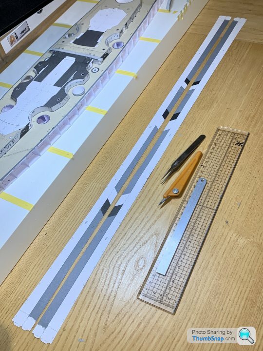
Continuing with the hull sides which are by far the most difficult bits of paper modelling I’ve done so far. Not only do the camo chevrons have to line up, but they are obviously attached to the bow and stern pieces which must align with various anchor cut-outs:

…and deck cranks. Add into that that the long strips are subtly curved, and must be joined invisibly to get an acceptable result, it’s no wonder several attempts were needed - each one eating into the length of paper I’m working with:


There’s only one ideal position for each piece, so if the adjustments go too far, an entirely new spare piece needs splicing in:

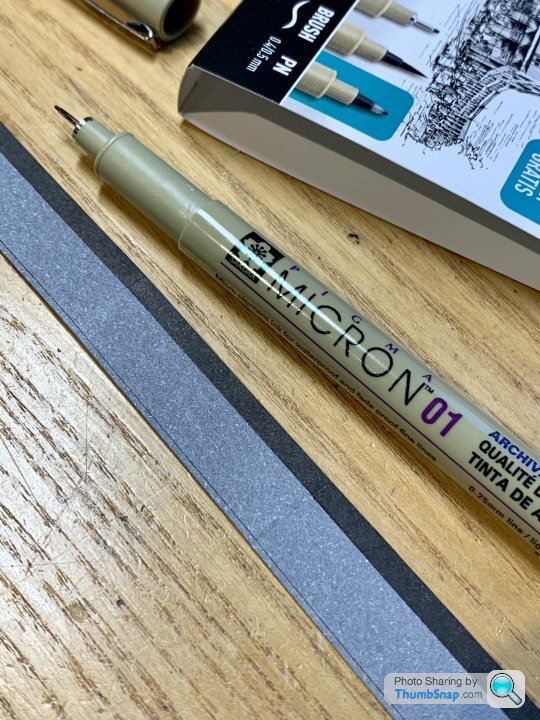
The black upper edge of the waterline didn’t line up on that repair, so I used my son’s drawing pens to add a bit in:
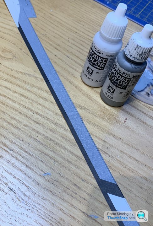
I found Vallejo paint can be mixed to a very good match, and after touching in any white bits, the results aren’t too bad:
The other complication with these sides is that they have a return along the top, which forms the upper ledge of the armour belt. These aren’t perfectly straight, so I came up with taping the strips to make them temporarily straight, which made scoring much easier:

So after multiple goes at temporarily taping all the bits into place, I got a decent result. This is the front half:

The back half is now done, and the plan is to fit the bow and stern sections in isolation, then make the final mid point splice along a camo line, so that the inevitable cutting error can be more easily disguised.
…and deck cranks. Add into that that the long strips are subtly curved, and must be joined invisibly to get an acceptable result, it’s no wonder several attempts were needed - each one eating into the length of paper I’m working with:
There’s only one ideal position for each piece, so if the adjustments go too far, an entirely new spare piece needs splicing in:
The black upper edge of the waterline didn’t line up on that repair, so I used my son’s drawing pens to add a bit in:
I found Vallejo paint can be mixed to a very good match, and after touching in any white bits, the results aren’t too bad:
The other complication with these sides is that they have a return along the top, which forms the upper ledge of the armour belt. These aren’t perfectly straight, so I came up with taping the strips to make them temporarily straight, which made scoring much easier:
So after multiple goes at temporarily taping all the bits into place, I got a decent result. This is the front half:
The back half is now done, and the plan is to fit the bow and stern sections in isolation, then make the final mid point splice along a camo line, so that the inevitable cutting error can be more easily disguised.
Gassing Station | Scale Models | Top of Page | What's New | My Stuff