Stuart Twin Victoria (Princess Royal) Mill Engine
Discussion


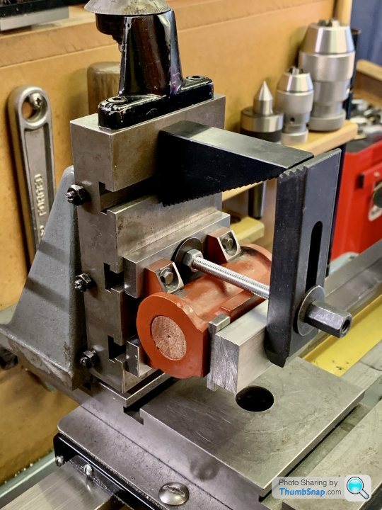
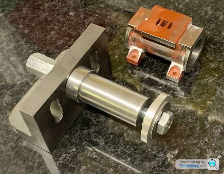
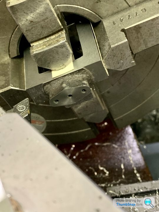
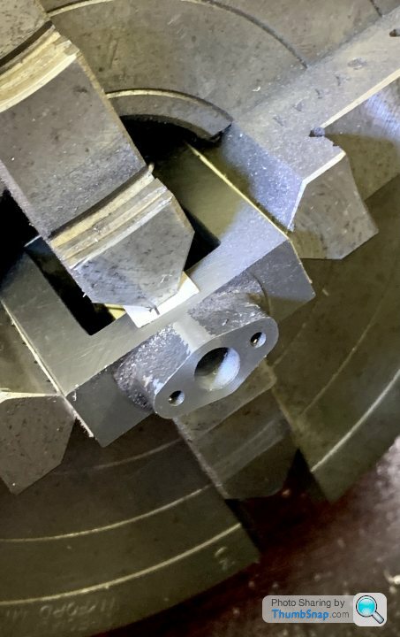
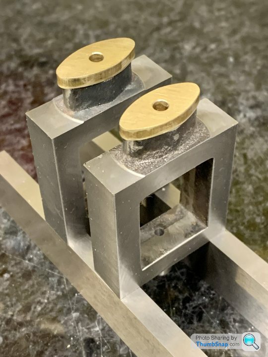
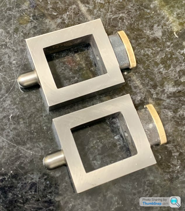
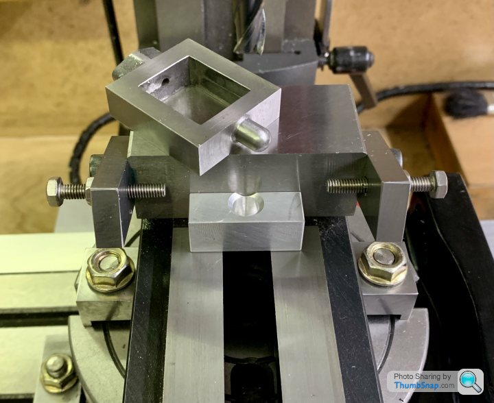
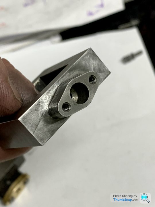
After some advice over on the ME forum, I changed the fixture to give more security:
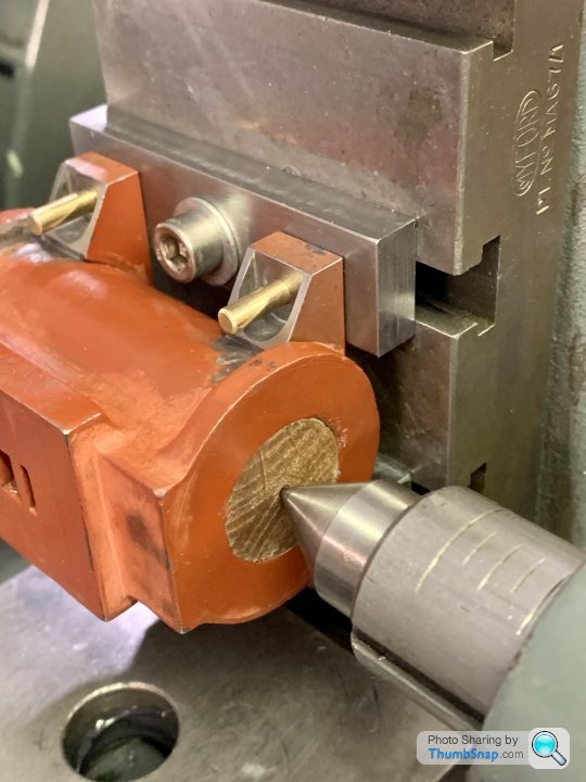
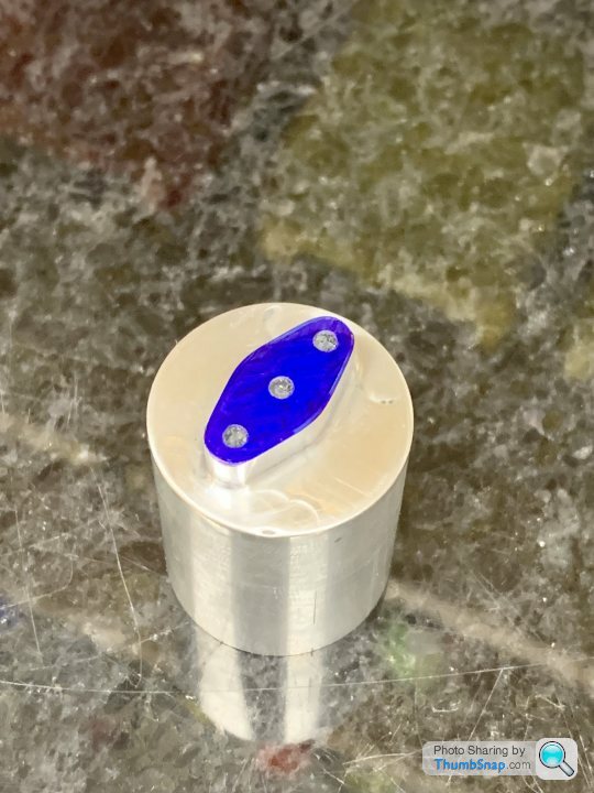
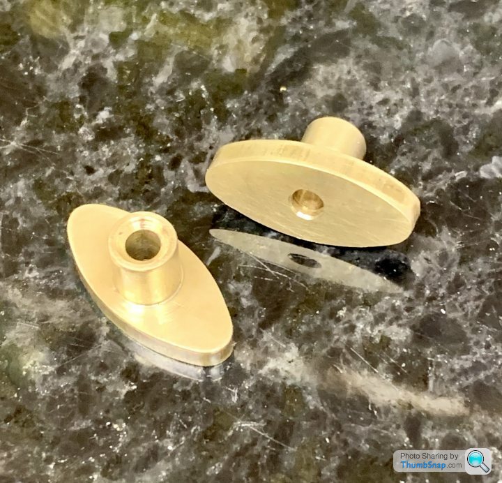
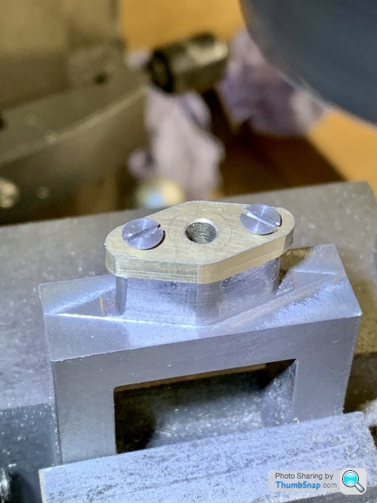
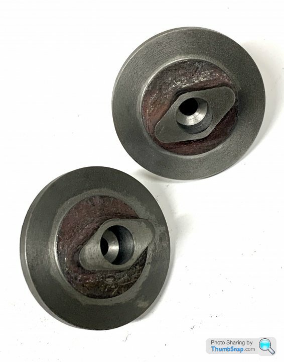
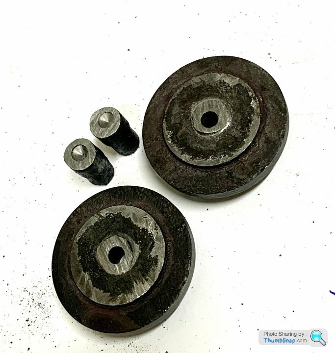
Made some brass pins to check alignment of the feet:
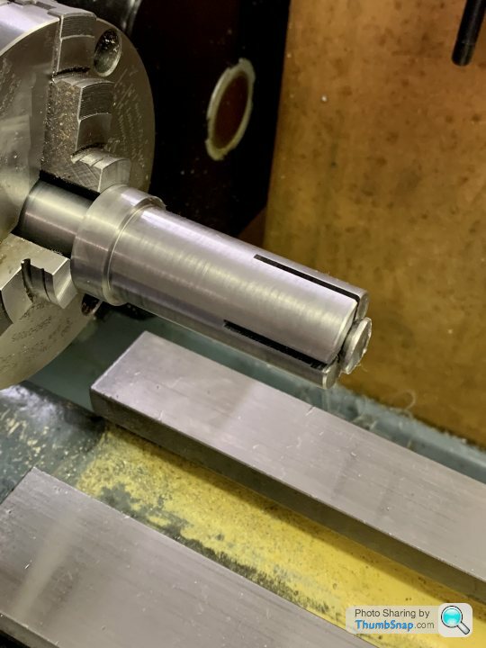
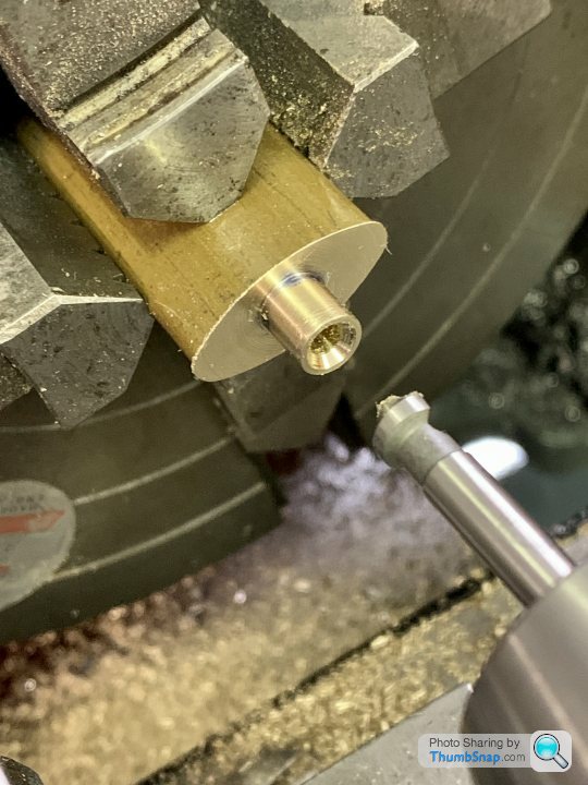
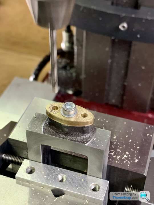
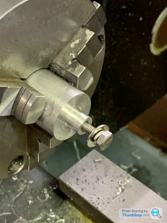
Then aligned the plug centres with the lathe centres:
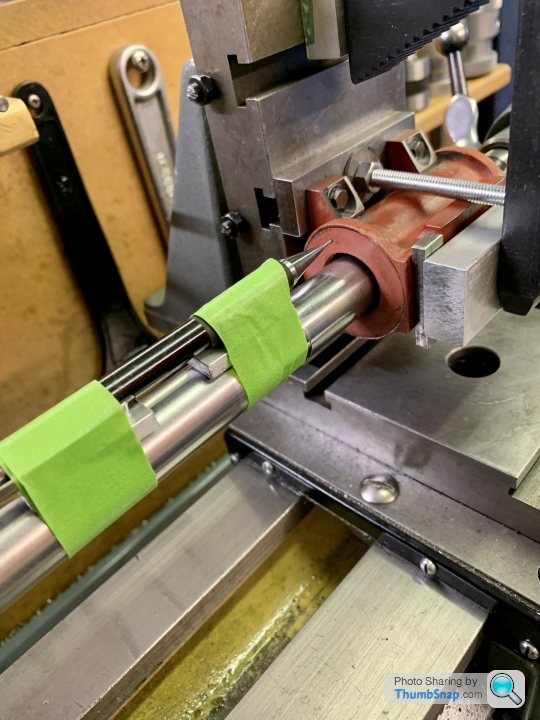
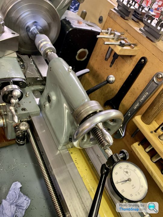
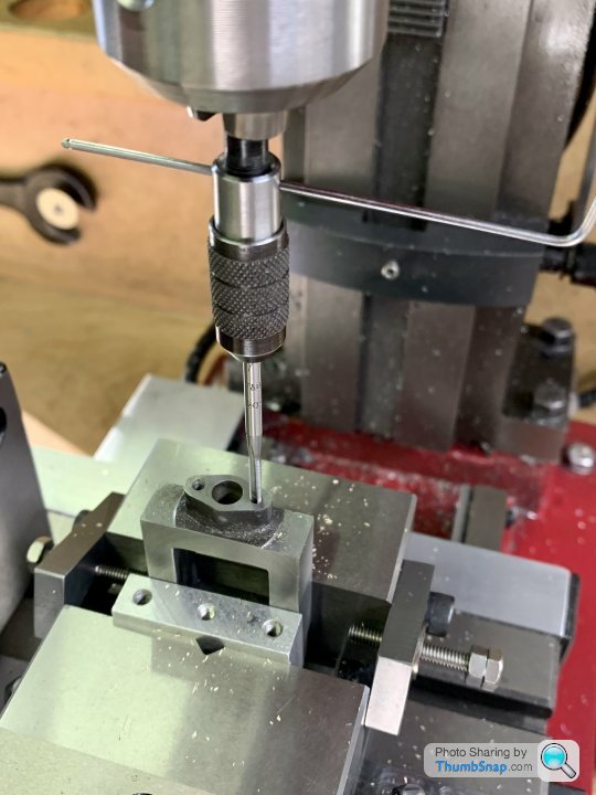
Then fitted the bar and taped a pencil to it to check concentricity with the cast flanges:
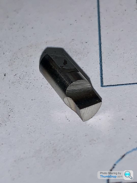
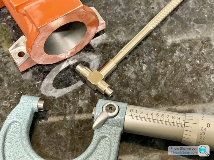
Then ground a tool bit:
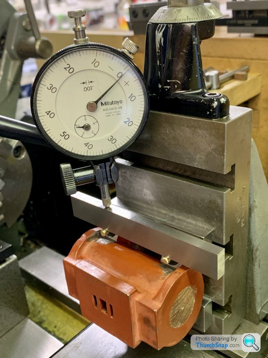
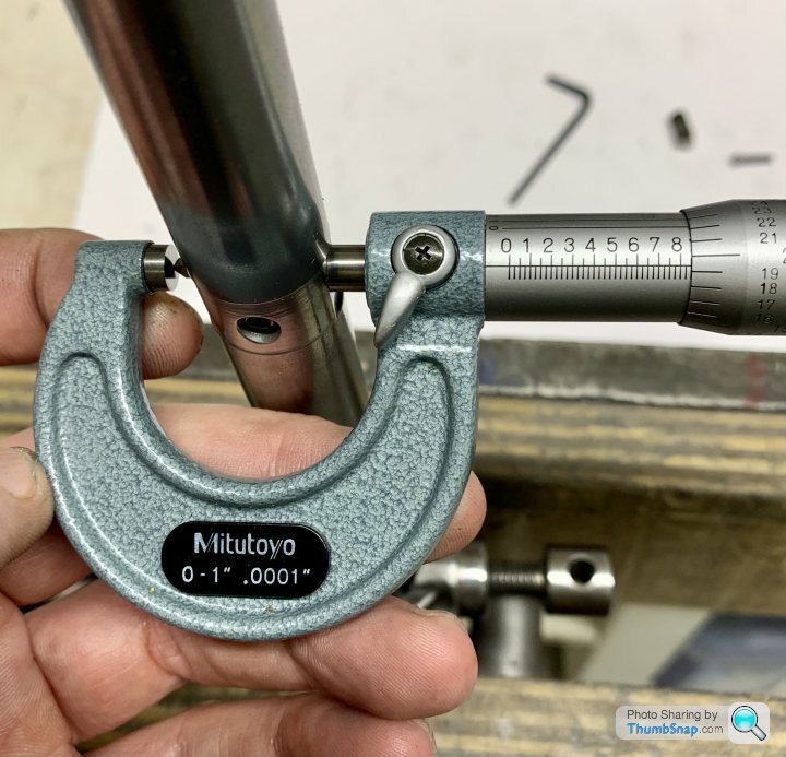
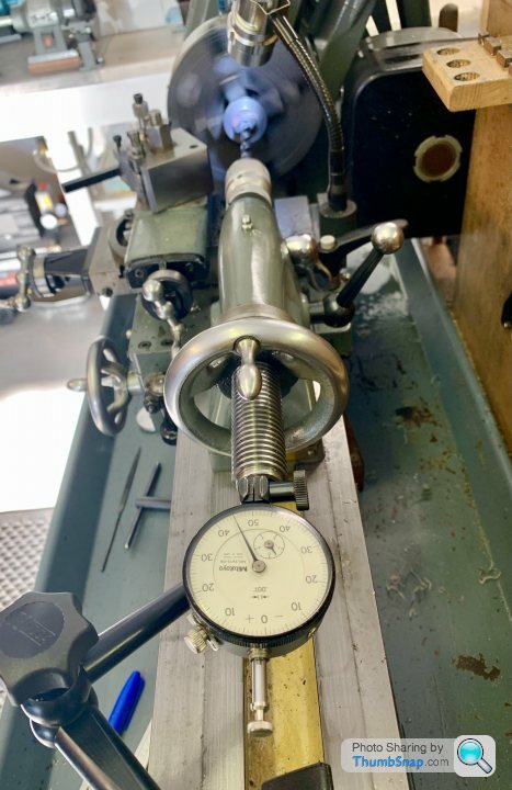
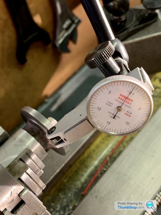
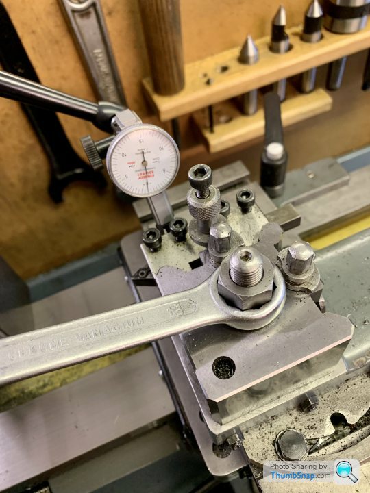
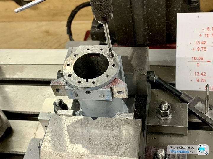
Set up with the micrometer as a baseline for subsequent adjustments:
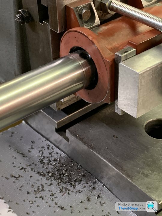
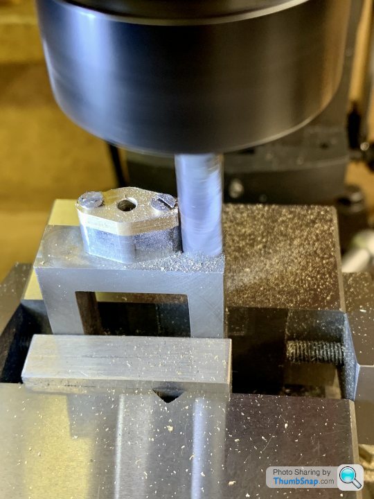
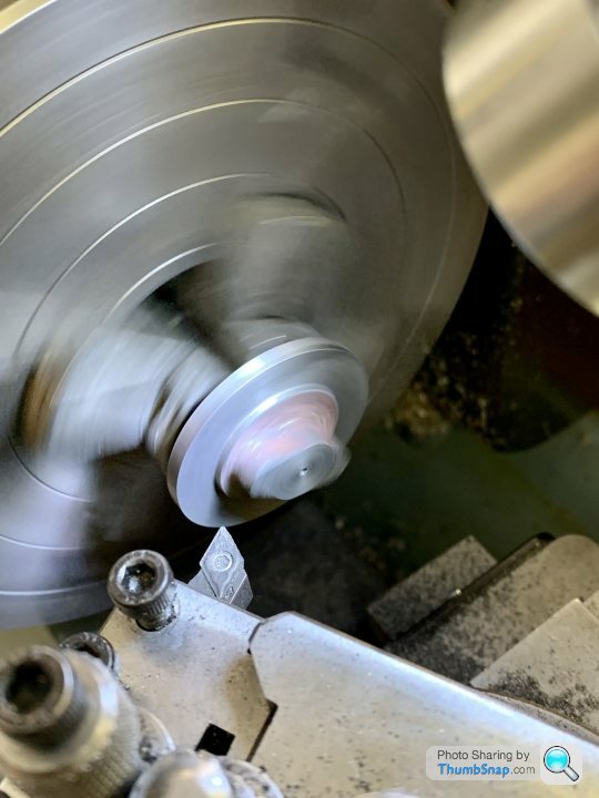
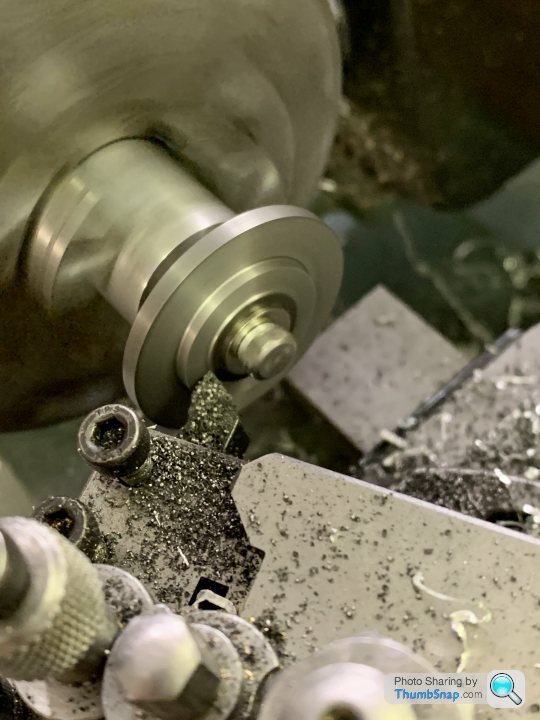
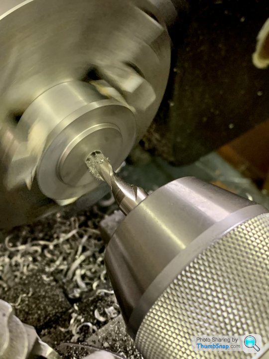
Then bit the bullet and made a start:
Seemed to go ok so for the final cuts made a radiussed bit to give a better surface finish:
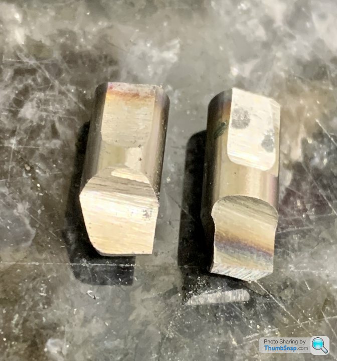
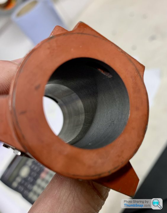
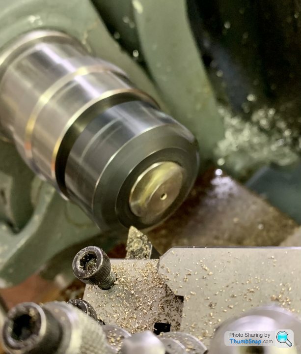
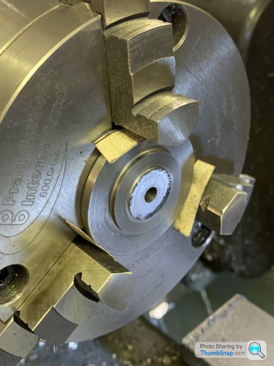
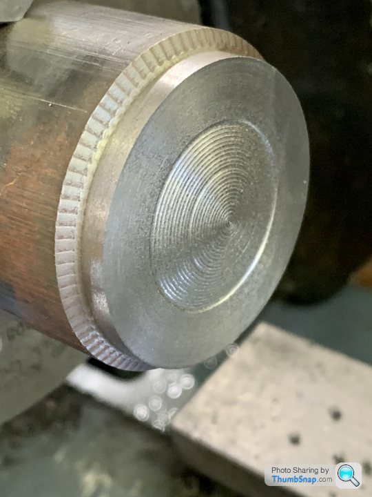
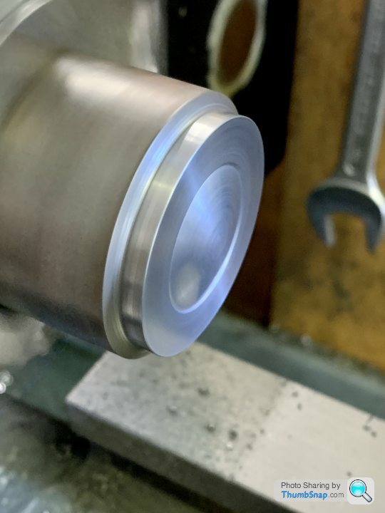
After a bit of re-profiling, got a good result, and managed to increment the cuts up to size:

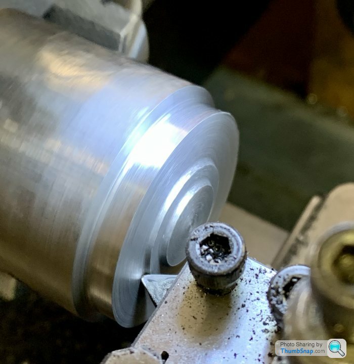
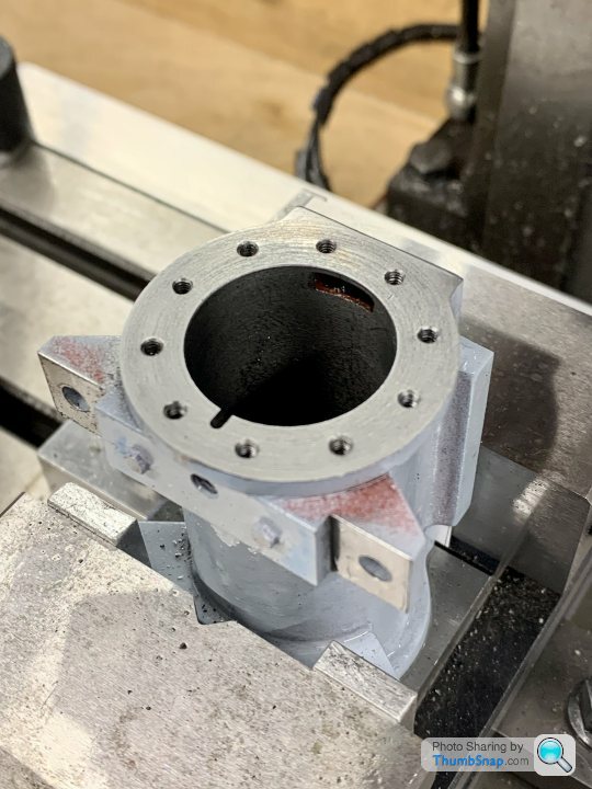
Cylindrical too, so I called it a result. There was a mystery discolouration half way along the bore; no ridge, and the same diameter all the way. A hard spot or inclusion slightly taking the edge off the tool was a suggested reason. Anyway, this effect should disappear with the super finishing later on:
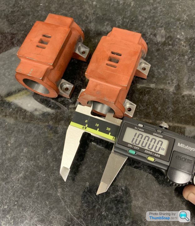
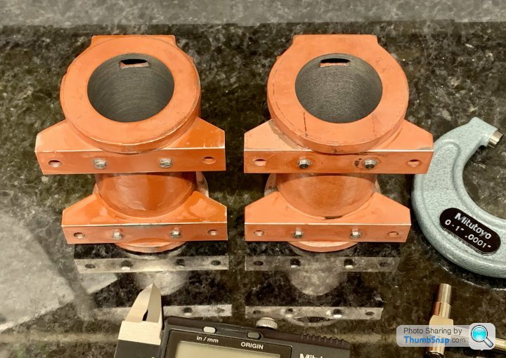
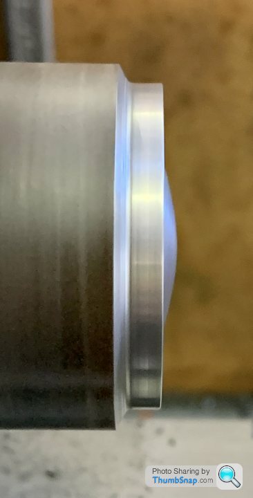
Second cylinder no problem:
Next job is to make a couple of mandrels for facing.
Made some brass pins to check alignment of the feet:
Then aligned the plug centres with the lathe centres:
Then fitted the bar and taped a pencil to it to check concentricity with the cast flanges:
Then ground a tool bit:
Set up with the micrometer as a baseline for subsequent adjustments:
Then bit the bullet and made a start:
Seemed to go ok so for the final cuts made a radiussed bit to give a better surface finish:
After a bit of re-profiling, got a good result, and managed to increment the cuts up to size:
Cylindrical too, so I called it a result. There was a mystery discolouration half way along the bore; no ridge, and the same diameter all the way. A hard spot or inclusion slightly taking the edge off the tool was a suggested reason. Anyway, this effect should disappear with the super finishing later on:
Second cylinder no problem:
Next job is to make a couple of mandrels for facing.
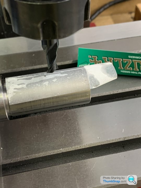
Always wanted to try using Rizla paper to find the surface of something, 0.0005” according to the verniers, so there we go…
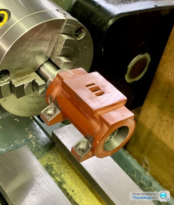
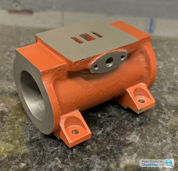
Then machined the feet using the valve face as a reference:
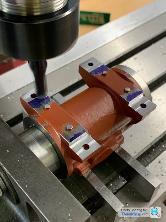
Set up at 90 degrees to the valve face using a 1-2-3 block
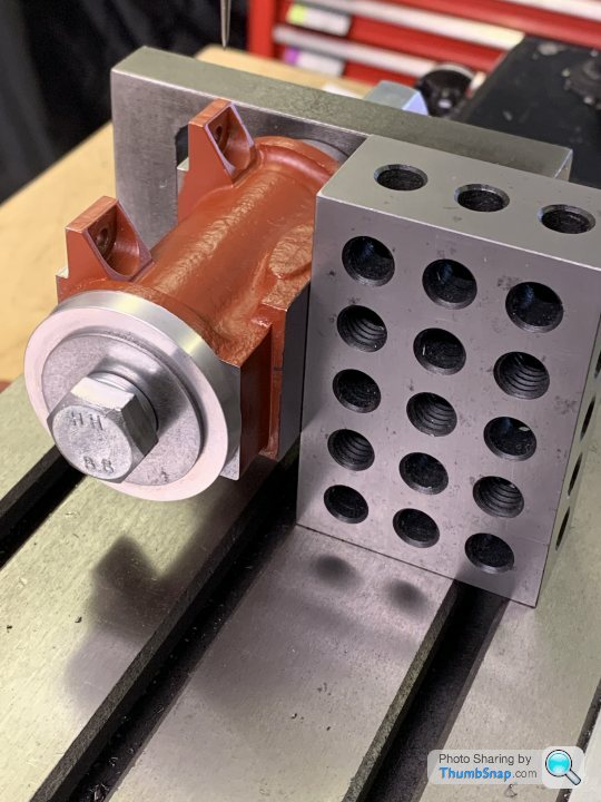
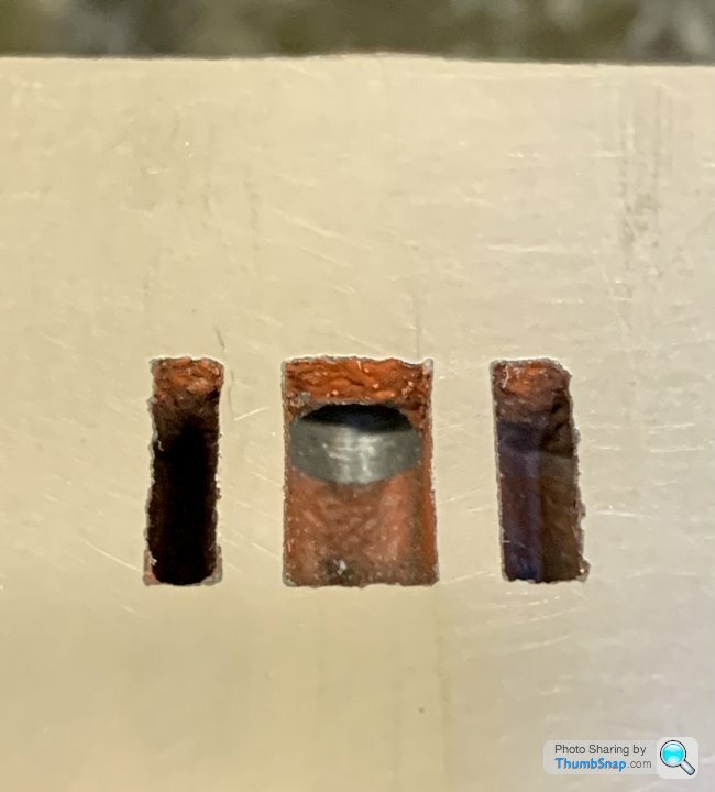
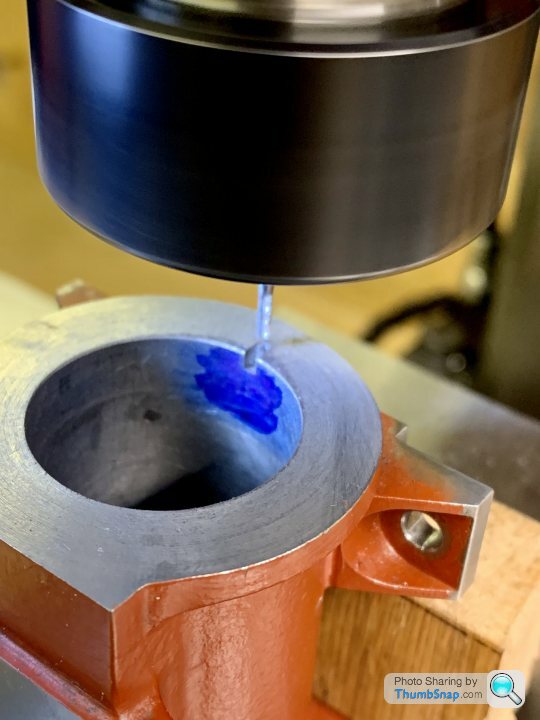
Then faced the exhaust pad with a 12mm end mill. It only just cleaned up at the specified offset from the axis
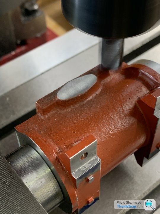
Then puzzled over whether to centre using the valve pad as the reference, or the cylinder ends. There was a very slight difference. Same with the offset from the valve face. Only a matter of 0.004” or so in both cases, but in the end I used the valve pad and the exhaust pad as references:
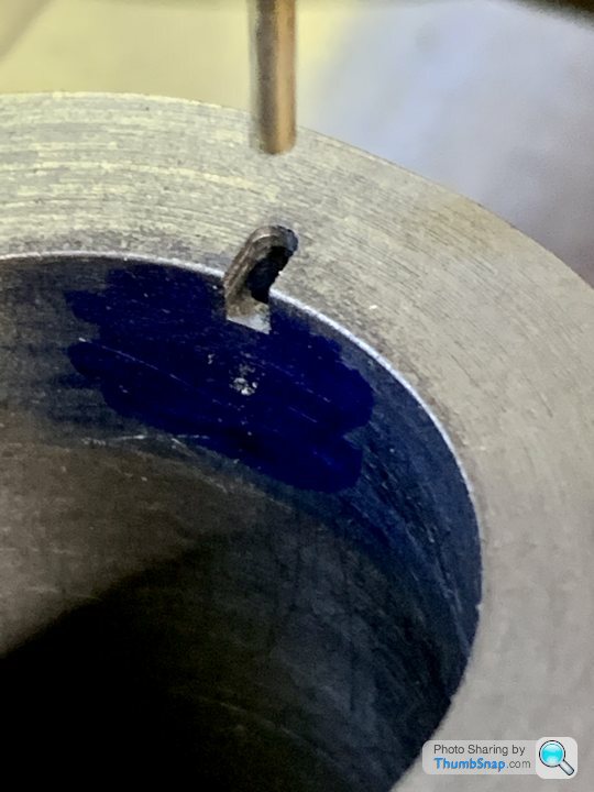
Double-check with the port seemed to confirm it was about right:
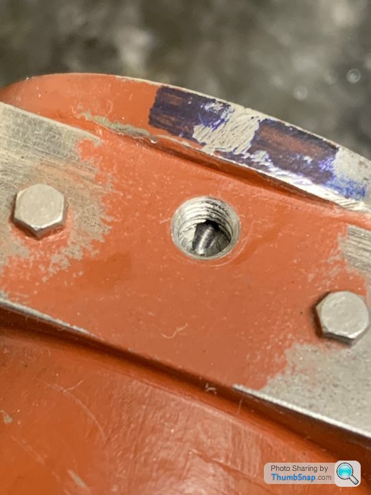
And since I’m using the DROs, I ignored the instructions to mark from the port block, and drilled and tapped the securing holes:
The exhaust hole broke through right where it should:
Now to do it all over again with the other cylinder.
Then machined the feet using the valve face as a reference:
Set up at 90 degrees to the valve face using a 1-2-3 block
Then faced the exhaust pad with a 12mm end mill. It only just cleaned up at the specified offset from the axis
Then puzzled over whether to centre using the valve pad as the reference, or the cylinder ends. There was a very slight difference. Same with the offset from the valve face. Only a matter of 0.004” or so in both cases, but in the end I used the valve pad and the exhaust pad as references:
Double-check with the port seemed to confirm it was about right:
And since I’m using the DROs, I ignored the instructions to mark from the port block, and drilled and tapped the securing holes:
The exhaust hole broke through right where it should:
Now to do it all over again with the other cylinder.
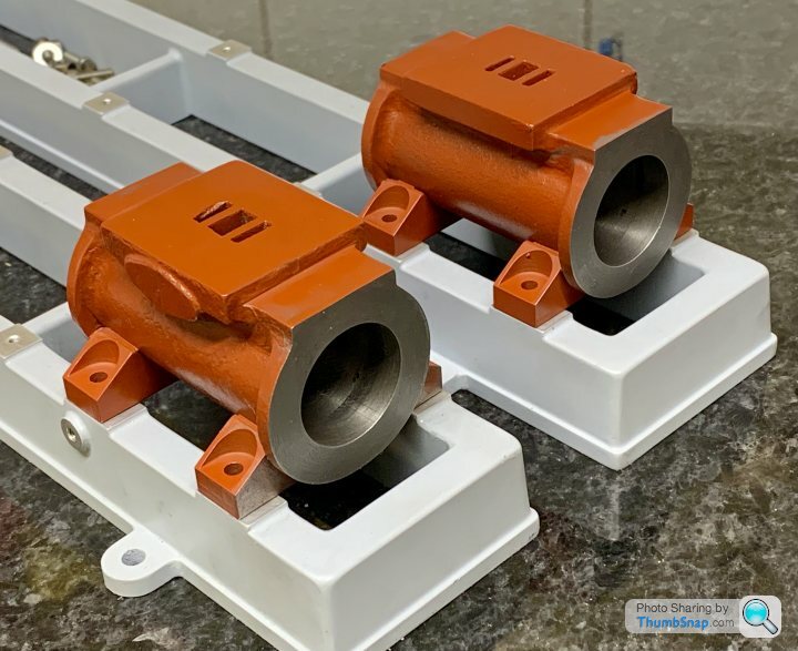
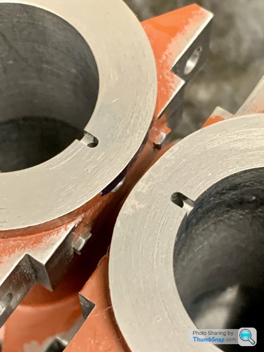
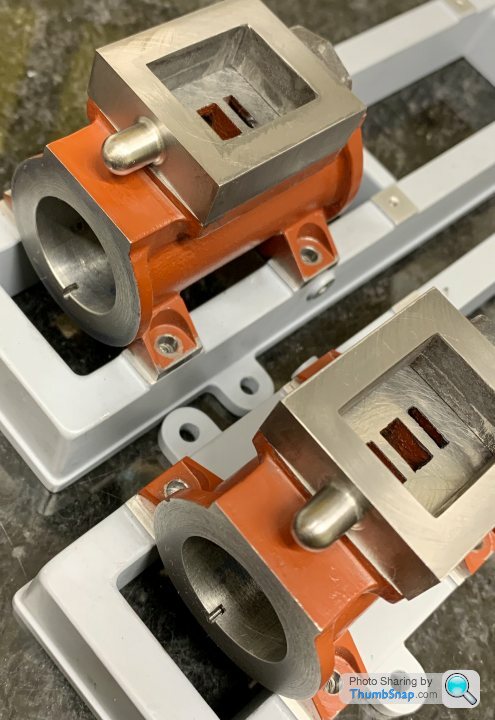
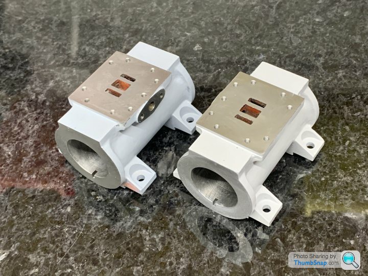
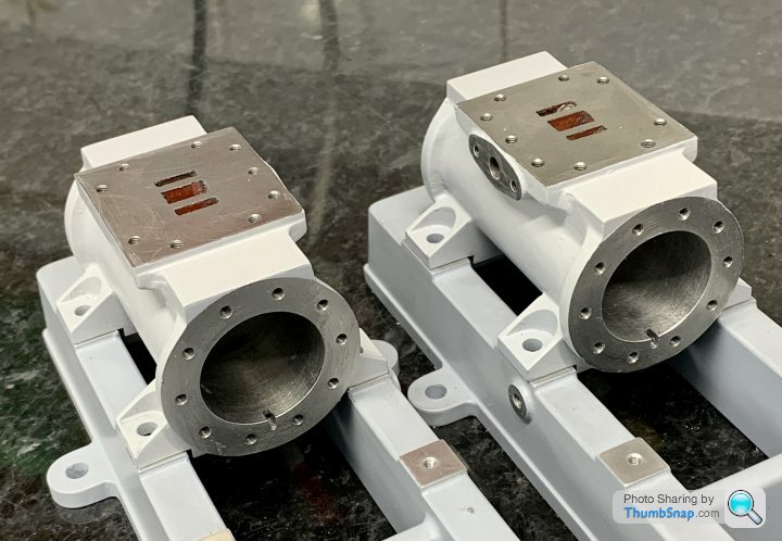
Struggling with motivation do to anything at the moment - maybe I’ve got too many projects on, or maybe it’s delayed lockdown blues. Anyway, got the other cylinder exhaust port and feet done:

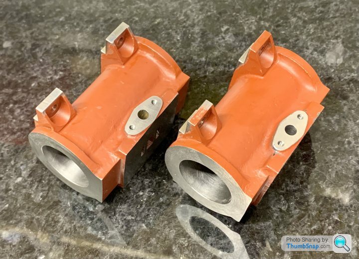
They both seem to be ok in terms of heights and lengths etc., and the thickened Milliput flange isn’t really noticeable either. So the next thing I want to get done are the angled drillings for the drain cocks. I think I’ll drill and tap the feet for the cocks (or unions), then angle the cylinders in the vice and use the long series centre drill to start a hole, then drill and hope it breaks into the drain cock hole…
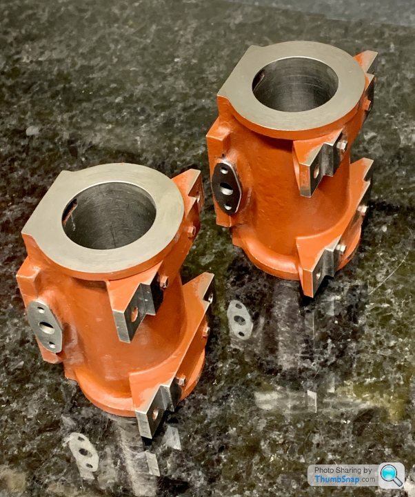
Then it’ll be on to drilling the cylinder cover holes and figuring out some revised hole positions for the valve chests:

That will be interesting seeing as they are a bit small, and the corner holes seem to have wafer thin edges.
They both seem to be ok in terms of heights and lengths etc., and the thickened Milliput flange isn’t really noticeable either. So the next thing I want to get done are the angled drillings for the drain cocks. I think I’ll drill and tap the feet for the cocks (or unions), then angle the cylinders in the vice and use the long series centre drill to start a hole, then drill and hope it breaks into the drain cock hole…
Then it’ll be on to drilling the cylinder cover holes and figuring out some revised hole positions for the valve chests:
That will be interesting seeing as they are a bit small, and the corner holes seem to have wafer thin edges.
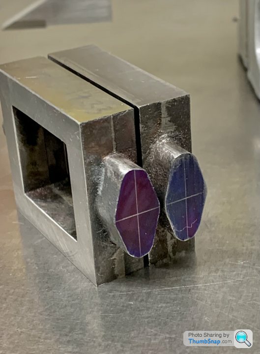
Made some progress on the steam chests today. I may have done this arse about face, but it seems to have worked…
Started by putting the chests in the 4-jaw and cleaning up the gland faces (not to any particular dimension)
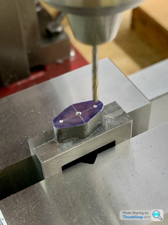
Then using the height gauge, scribing the centres of the ovals by measuring the major and minor dims, and offsetting the scriber by half:

From there I could easily figure out how much to remove from the previously cleaned-up faces:


Then the sides, making them all the same as the minimum clean-up side:
Then set up in the mill to drill some pilot holes for the flanges:
Then setup in the 4-jaw to get the valve rod hole centred (its offset). Once set, I loosened 2 of the jaws, and spun the part 180 degrees so I could machine the dome end:
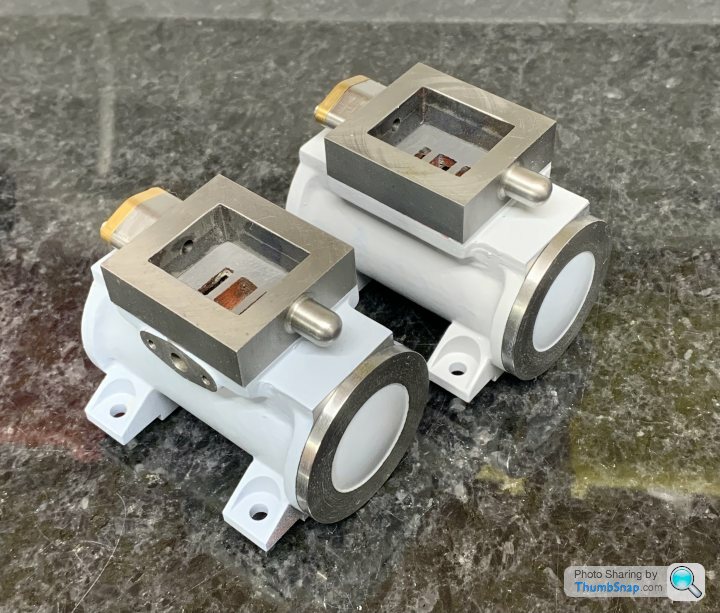
This cleaned up OK:
And the other:
They actually measure within a few thou of each other in overall height, which is surprising since the end facing of the ovals wasn’t to a dimension yet:

Slightly concerning that even without the oval ends being machined, they’re very short to the valve face pads:
Still, I only did the absolute minimum clean-up so it is what it is:

Very pleased with the height gauge - it got lots of use already, and made things so much easier for these parts. Now waiting for the RT to arrive - just in time for profiling the oval bosses.
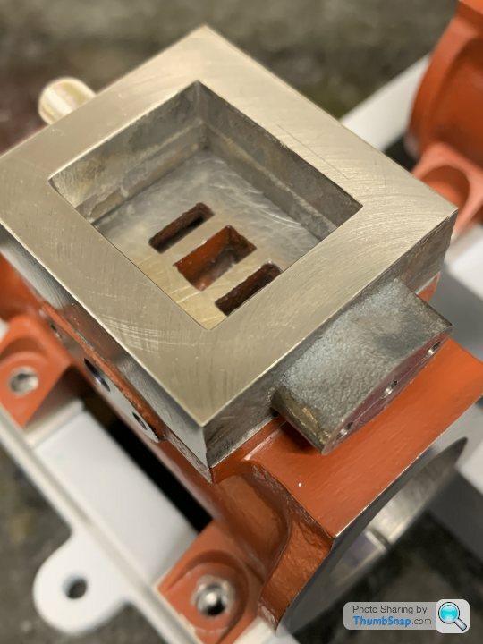
BTW, also increased the drain slots from 2mm to 3mm long.
Started by putting the chests in the 4-jaw and cleaning up the gland faces (not to any particular dimension)
Then using the height gauge, scribing the centres of the ovals by measuring the major and minor dims, and offsetting the scriber by half:
From there I could easily figure out how much to remove from the previously cleaned-up faces:
Then the sides, making them all the same as the minimum clean-up side:
Then set up in the mill to drill some pilot holes for the flanges:
Then setup in the 4-jaw to get the valve rod hole centred (its offset). Once set, I loosened 2 of the jaws, and spun the part 180 degrees so I could machine the dome end:
This cleaned up OK:
And the other:
They actually measure within a few thou of each other in overall height, which is surprising since the end facing of the ovals wasn’t to a dimension yet:
Slightly concerning that even without the oval ends being machined, they’re very short to the valve face pads:
Still, I only did the absolute minimum clean-up so it is what it is:
Very pleased with the height gauge - it got lots of use already, and made things so much easier for these parts. Now waiting for the RT to arrive - just in time for profiling the oval bosses.
BTW, also increased the drain slots from 2mm to 3mm long.
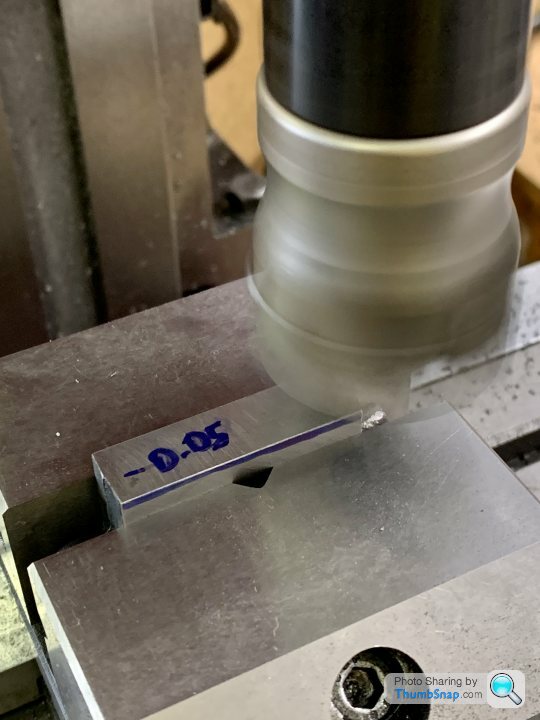
Had a day off work today, so cracked on with the valve rod gland bosses. I want the gunmetal glands to match the shape of the bosses, at the moment they are different. I figured out some geometry that should enable me to use the R/T to mill them together. Did a test on some aluminium, that worked ok:
So on to the real thing: mounted the chests in the 4 jaw chuck and skimmed the faces to give a consistent depth datum to mill to:
Then drilled the valve rod holes and packing space:
Also faced the boss again to get the right protrusion:
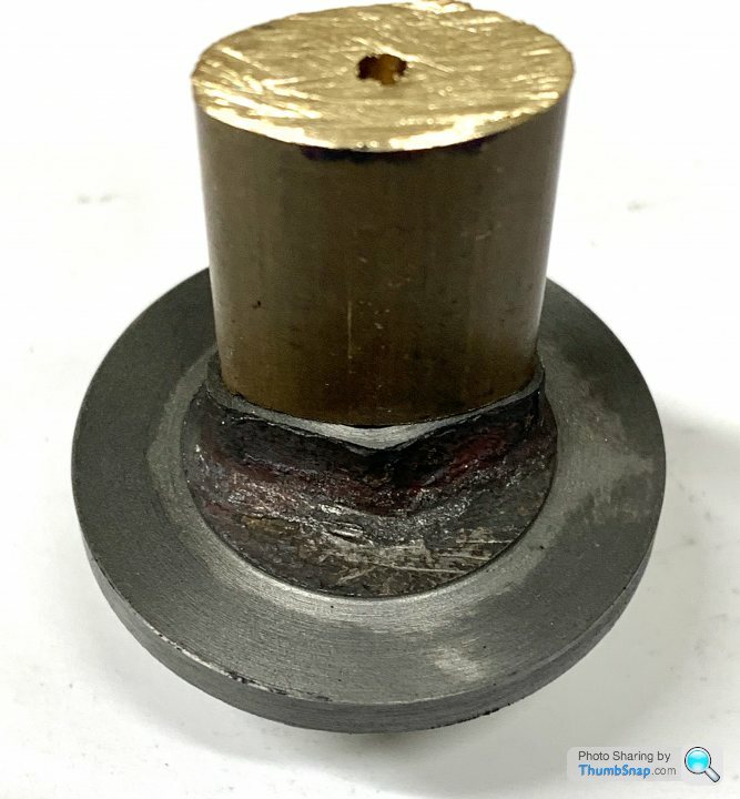
Then set the gunmetal extrusion in the 4-jaw and turned the spigot to fit the packing hole:
Didn’t fancy parting it off, so went at it with the hacksaw:

Then reversed it and put in the collet chuck to face the front:
Finished:
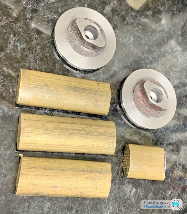
Just need the 7BA clearance holes drilling, then I can bolt them to the chests for milling the sides:
You can see how oversized the gunmetal is here:

If I’ve done my sums right, the mill profile should just skim the cast iron boss and in the process take the excess gunmetal with it, leaving them identical.
So on to the real thing: mounted the chests in the 4 jaw chuck and skimmed the faces to give a consistent depth datum to mill to:
Then drilled the valve rod holes and packing space:
Also faced the boss again to get the right protrusion:
Then set the gunmetal extrusion in the 4-jaw and turned the spigot to fit the packing hole:
Didn’t fancy parting it off, so went at it with the hacksaw:
Then reversed it and put in the collet chuck to face the front:
Finished:
Just need the 7BA clearance holes drilling, then I can bolt them to the chests for milling the sides:
You can see how oversized the gunmetal is here:
If I’ve done my sums right, the mill profile should just skim the cast iron boss and in the process take the excess gunmetal with it, leaving them identical.
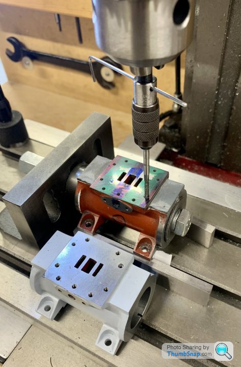
Temporarily clamped the bosses to the castings, and drilled the 7BA clearance holes using the DROs:
Then tapped the stud holes:
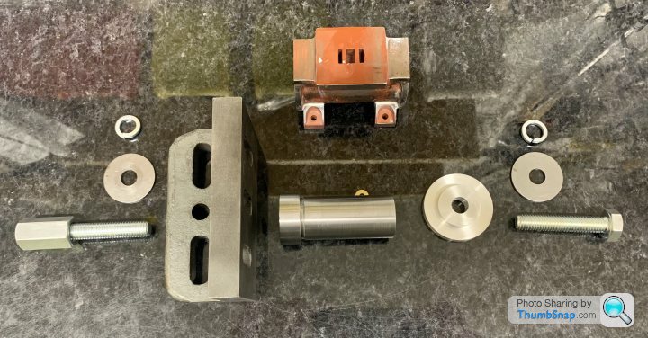
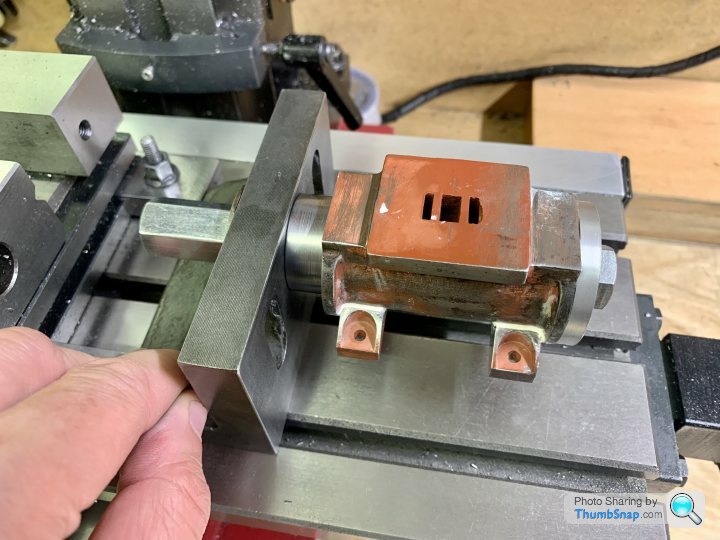
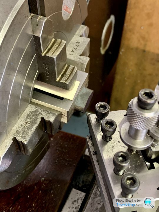
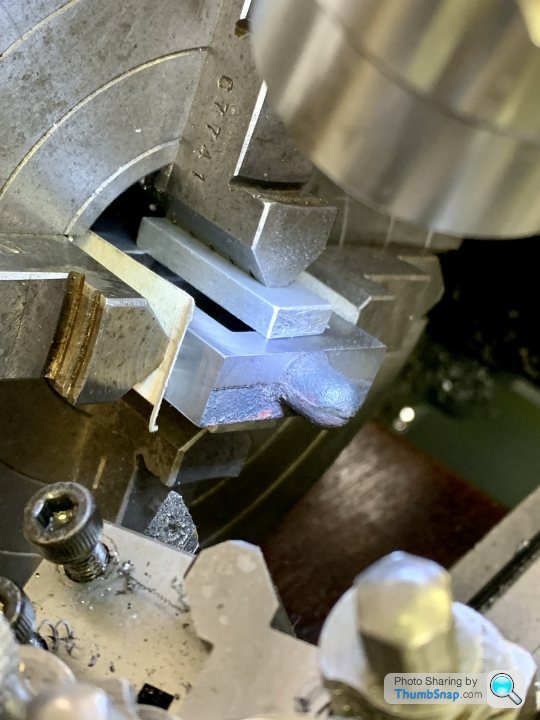
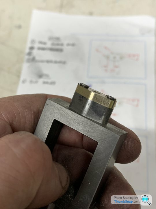
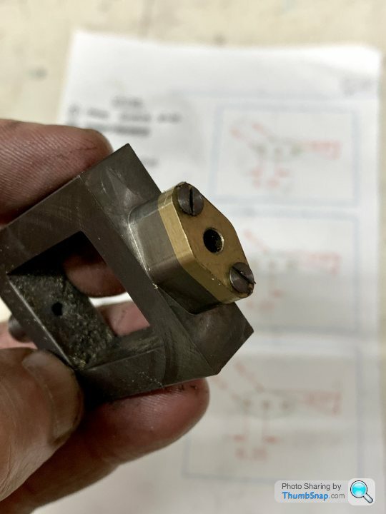
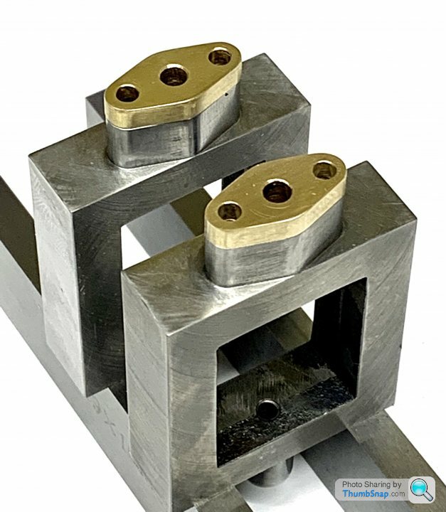
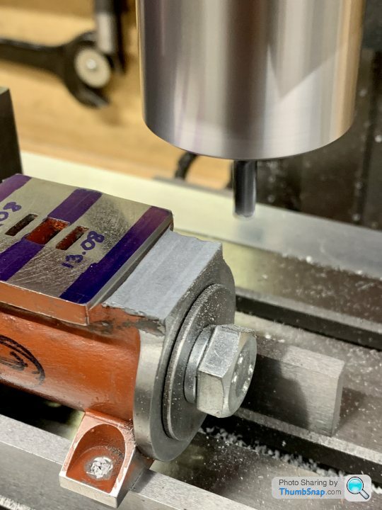
Then fixed them using 7BA csk screws ready for machining, and centered the vice on the R/T:
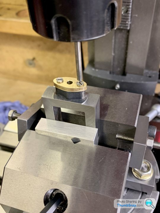
I’d previously made this adjustable fixture for the vice so I could slide the chest side to side to get the right offsets for centering on the rotary table for the mid and end radii:
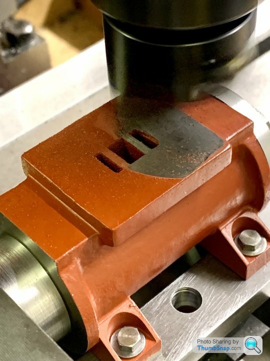
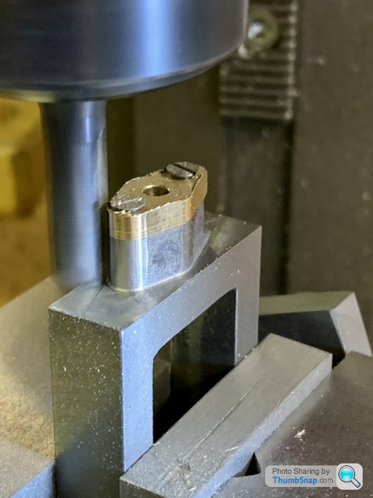
Then, after much adjustment, centering and angle calculation, made a start on milling the profile while periodically moving in x, then rotation in z, at gradually increasing depts of cut:
Then re-centered on each end, using the vice stops, and rotated the table to give the radii:
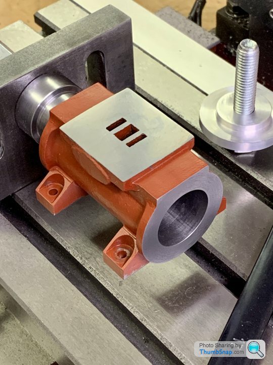
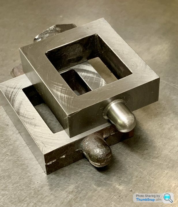
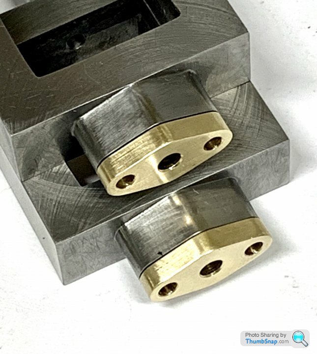
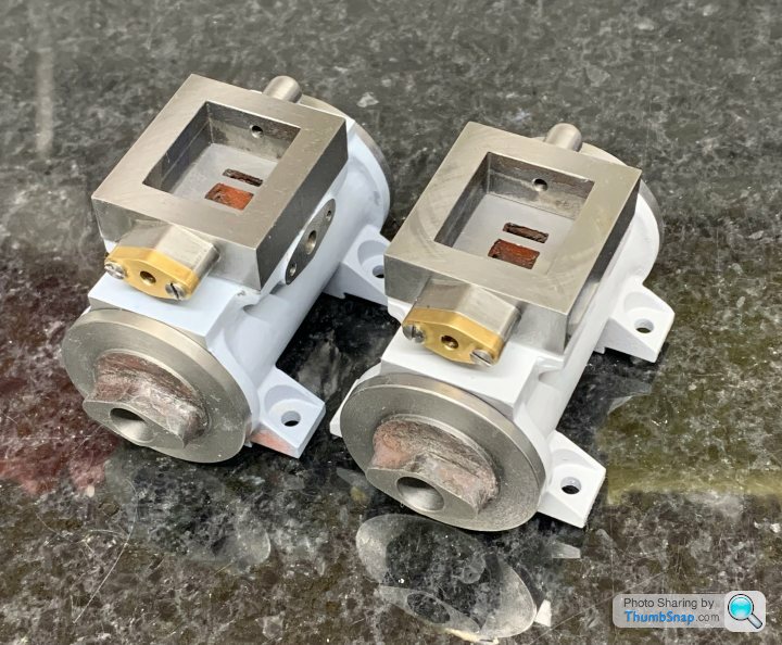
Turned out OK for a first attempt:
Before and after:

Needs some flatting of the machining marks. Not a big deal because they will be painted eventually:
Now for the other one…
Then tapped the stud holes:
Then fixed them using 7BA csk screws ready for machining, and centered the vice on the R/T:
I’d previously made this adjustable fixture for the vice so I could slide the chest side to side to get the right offsets for centering on the rotary table for the mid and end radii:
Then, after much adjustment, centering and angle calculation, made a start on milling the profile while periodically moving in x, then rotation in z, at gradually increasing depts of cut:
Then re-centered on each end, using the vice stops, and rotated the table to give the radii:
Turned out OK for a first attempt:
Before and after:
Needs some flatting of the machining marks. Not a big deal because they will be painted eventually:
Now for the other one…
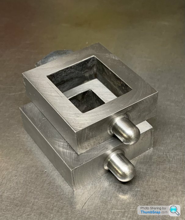
Got the other side done this morning:
I was given a set of small files, so used them to get rid of the larger machining marks. I found using a flat one, bowed very slightly convex was good for dealing with the surfaces away from the edges:
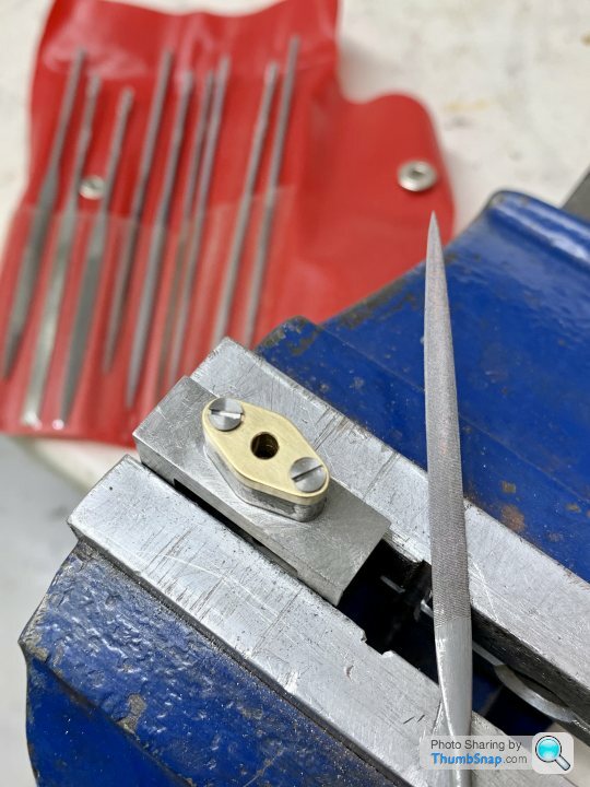
I do t have any Emery cloth, but used some #250 and #400 wet and dry lubricated with WD40. I would have gone further if they were to be left as bare metal, but I think as they are will give a good key for the primer:
This is the result:
I aimed to remove the absolute minimum from the castings, and the result was that a few places were missed:
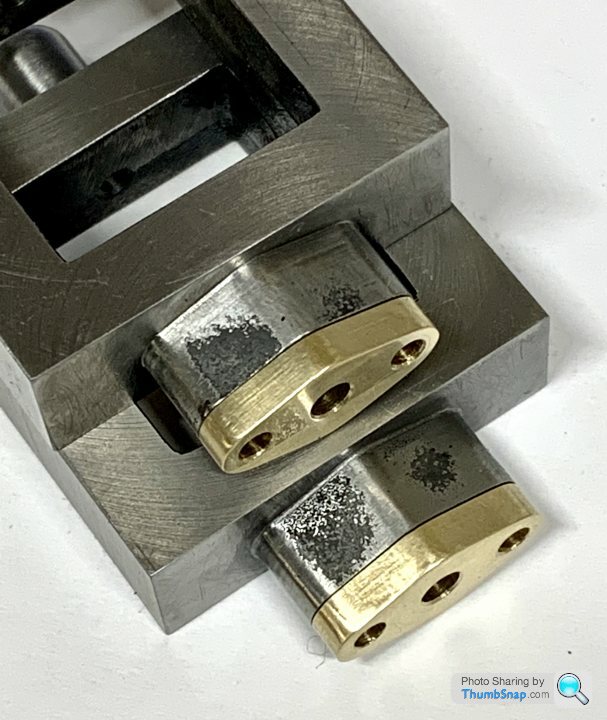
I opted to leave them because a) I think they are the undersides, and won’t be visible once assembled, and b) Once painted it won’t be obvious anyway.
I was given a set of small files, so used them to get rid of the larger machining marks. I found using a flat one, bowed very slightly convex was good for dealing with the surfaces away from the edges:
I do t have any Emery cloth, but used some #250 and #400 wet and dry lubricated with WD40. I would have gone further if they were to be left as bare metal, but I think as they are will give a good key for the primer:
This is the result:
I aimed to remove the absolute minimum from the castings, and the result was that a few places were missed:
I opted to leave them because a) I think they are the undersides, and won’t be visible once assembled, and b) Once painted it won’t be obvious anyway.
anonymous said:
[redacted]
I’ve got to live long enough to finish it first…I bought some Traction engine castings recently. I’m the third owner; first owner died, second owner got too old to start the model. The certified boiler for that engine is made to order, and has a two year waiting list. People die before taking delivery, so sometimes they have one for immediate collection.
What a hobby.
I had a go at the cylinder covers this afternoon. I’ve read the article method loads of times, but still couldn’t make head or tail of the descriptions: It says machine the plain cover spigot first, to a good fit to the cylinder, the reason being that it centralises the packing…but there isn’t any packing on that cover.
It then says make the spigot on the gland cover ends (the ones with the packing) a slack fit. It also says to machine the spigot diameter after facing, to ensure concentricity. Surely concentricity doesn’t depend on the face being true, plus if it’s slack, why is it important?
I was left wondering why in those cases bother with either spigot at all since one has nothing to centre, and the other is a slack fit anyway.
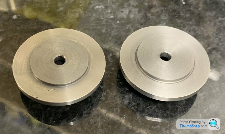
In the end I just went with what seemed logical. I assume when the article was written, the covers didn’t come with cast tails on the back, so I used those to mount in the chuck. I first faced the gland bosses, centre drilled them as best I could on the mill after marking with the verniers, and set up true in the 4 jaw. Then turned the bolt faces and re-faced the gland bosses to the correct depths:
Then drilled the piston rod and packing holes:
The 10V piston hole was reamed, but it says not to bother for this one. Which seems logical since it’s the piston and cross head that seem to define the rod position. Adding a third fit seems pointless, especially when the packing will centralise the rod. Anyway, that got me here:
Then sawed off the tails:
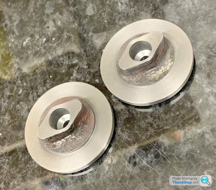
Made a mandrel as per the article:
Set up with a dti (both were within 0.002” O/D and 0.001” on the face, so I thought that was ok:
And turned the inside spigots and the flanges to thickness. I made the spigots a good fit to the cylinders. I can slacken them off if I need to I suppose:
Then finished the spigot faces in the 3 jaw:
I guess there was better way to do it than this, but it seemed to work ok:
The castings where right on the edge of being big enough for the stated dimensions, in fact there are still a couple of pinholes on one of the gasket faces. The brass extrusion I bought was never going to be big enough to make the glands:
Got plenty spare…
I’ve got some brass bar, so I’ll try to make them from that:
Lessons learned: I should have bored the packing holes rather than drilled them - my smallest boring bar will just fit. Oh well, I think they will be ok.
Next job is to make a mounting block for them for the R/T vice, and get them milled as per the valve blocks. I might put some JB Weld around the bosses - they look very close to being undersized despite everything being pretty central.
It then says make the spigot on the gland cover ends (the ones with the packing) a slack fit. It also says to machine the spigot diameter after facing, to ensure concentricity. Surely concentricity doesn’t depend on the face being true, plus if it’s slack, why is it important?
I was left wondering why in those cases bother with either spigot at all since one has nothing to centre, and the other is a slack fit anyway.
In the end I just went with what seemed logical. I assume when the article was written, the covers didn’t come with cast tails on the back, so I used those to mount in the chuck. I first faced the gland bosses, centre drilled them as best I could on the mill after marking with the verniers, and set up true in the 4 jaw. Then turned the bolt faces and re-faced the gland bosses to the correct depths:
Then drilled the piston rod and packing holes:
The 10V piston hole was reamed, but it says not to bother for this one. Which seems logical since it’s the piston and cross head that seem to define the rod position. Adding a third fit seems pointless, especially when the packing will centralise the rod. Anyway, that got me here:
Then sawed off the tails:
Made a mandrel as per the article:
Set up with a dti (both were within 0.002” O/D and 0.001” on the face, so I thought that was ok:
And turned the inside spigots and the flanges to thickness. I made the spigots a good fit to the cylinders. I can slacken them off if I need to I suppose:
Then finished the spigot faces in the 3 jaw:
I guess there was better way to do it than this, but it seemed to work ok:
The castings where right on the edge of being big enough for the stated dimensions, in fact there are still a couple of pinholes on one of the gasket faces. The brass extrusion I bought was never going to be big enough to make the glands:
Got plenty spare…
I’ve got some brass bar, so I’ll try to make them from that:
Lessons learned: I should have bored the packing holes rather than drilled them - my smallest boring bar will just fit. Oh well, I think they will be ok.
Next job is to make a mounting block for them for the R/T vice, and get them milled as per the valve blocks. I might put some JB Weld around the bosses - they look very close to being undersized despite everything being pretty central.
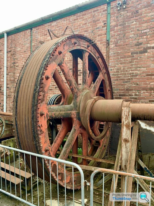
In other news, went to the Kelham Island museum this morning (it’s only 30 minutes from home). Parked next to a double flywheel similar to the one on the Twin Victoria. Never seen one before, it looks like it was part of some electrical machine judging by the circumferential details:
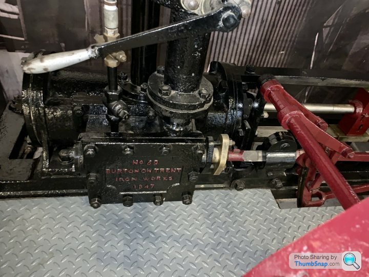
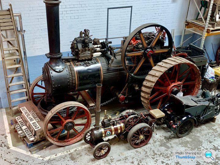
A few other engines:

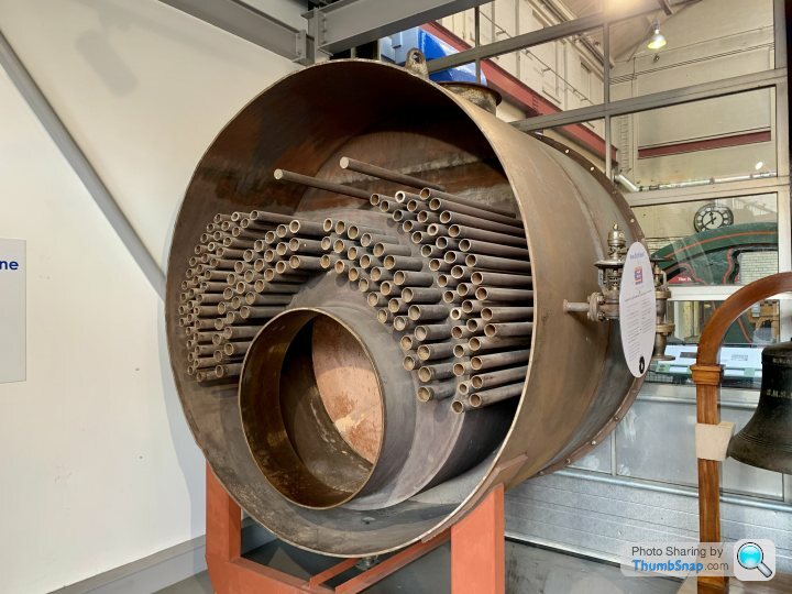
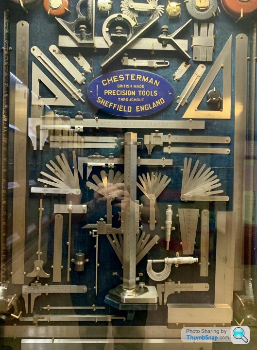
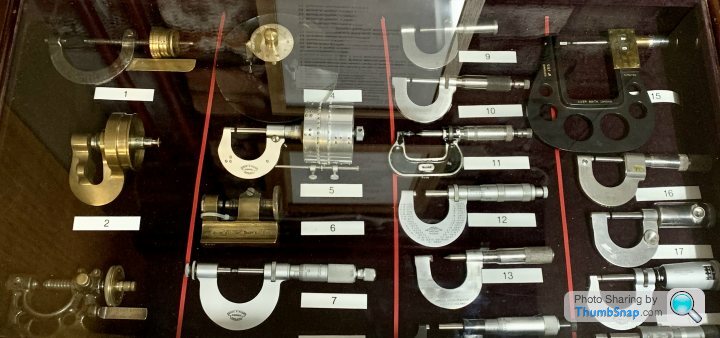
And things in glass cases (always good):
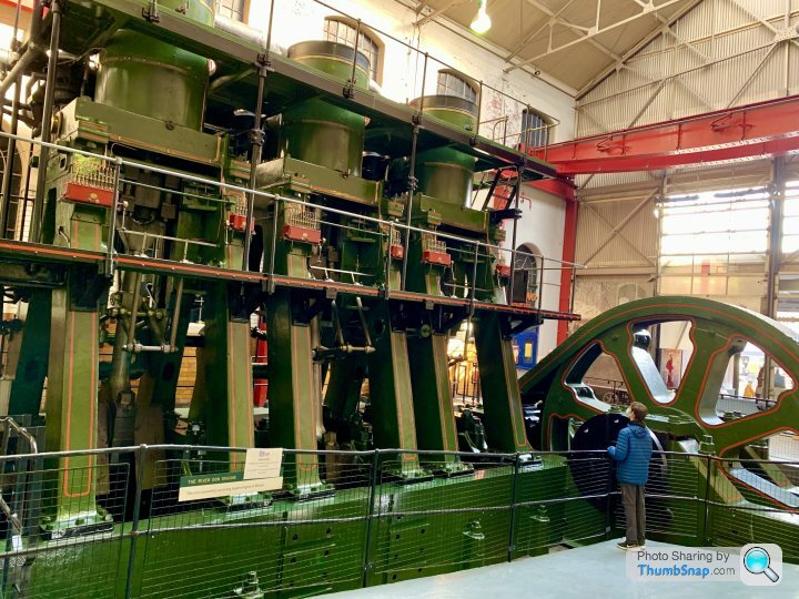
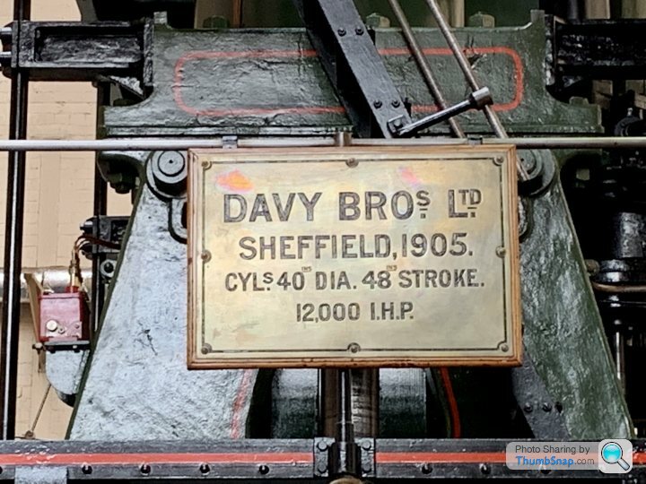
And of course the 12,000hp River Don engine:
Bought myself a poster for the workshop:
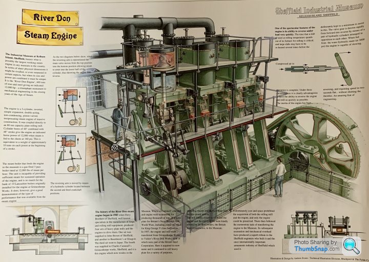
Unfortunately it wasn’t running today due to a boiler issue. I’m always amazed it can go from full forward speed to full reverse speed in 2 seconds, without shutting the throttles. It’s one of those things where you can feel the power just by standing near to it when it’s working. Same awesomeness as a Typhoon display, or being on the pit wall at Silverstone when the old 3.5 litre V10 F1 cars were current.
Other random stuff:
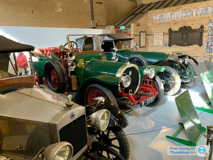
Sheffield Simplex:
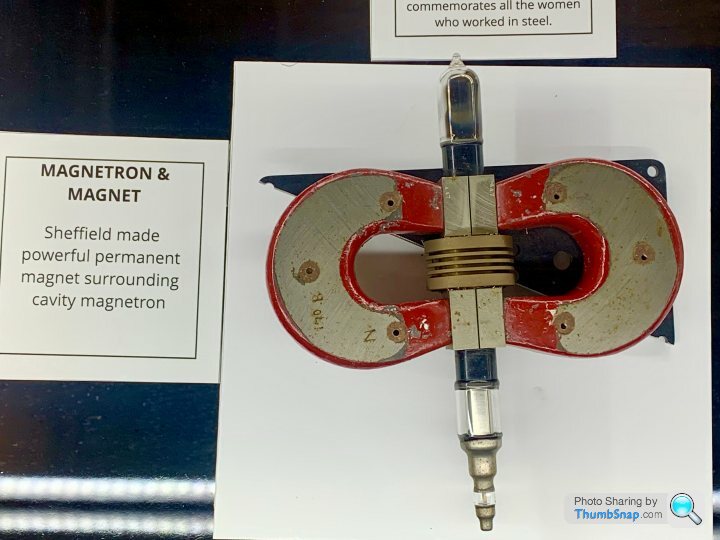
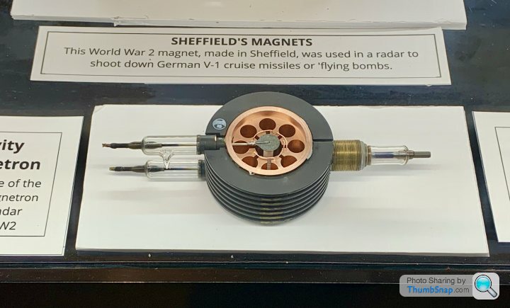
Cavity magnetron (with Sheffield made magnet!):
Anyway, a great museum, and it’s free (of course made a donation though).
A few other engines:
And things in glass cases (always good):
And of course the 12,000hp River Don engine:
Bought myself a poster for the workshop:
Unfortunately it wasn’t running today due to a boiler issue. I’m always amazed it can go from full forward speed to full reverse speed in 2 seconds, without shutting the throttles. It’s one of those things where you can feel the power just by standing near to it when it’s working. Same awesomeness as a Typhoon display, or being on the pit wall at Silverstone when the old 3.5 litre V10 F1 cars were current.
Other random stuff:
Sheffield Simplex:
Cavity magnetron (with Sheffield made magnet!):
Anyway, a great museum, and it’s free (of course made a donation though).
dudleybloke said:
dr_gn said:
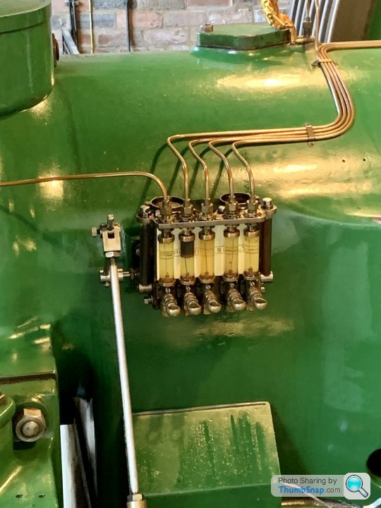
Are they the ones with an arm that rotates?
They have a reservoir Inline with the centre of rotation that looks like its defying gravity.Best example I've seen is on the huge mill engine at Trencherfield Mill in Wigan.
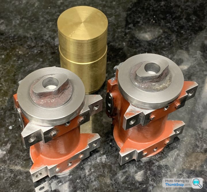
The back cylinder caps are domed, and this was a challenge. I took the advice I understood from the ME forums, and drew out the profile in CAD, then machined from a bar of cast iron:

I set the tool parallel to the bed:
And using more CAD:

Roughed the domes out:
Then using co-ordinates, approximated the profile:
Then using a combination of a dremel, files and abrasive paper:

Smoothed to shape:
Parted off using the home made rear post from earlier this year (worked great):

Then made a spacer ring and reversed in the chuck to turn and mill the inside details:
Took a few goes, but eventually I got a decent result:
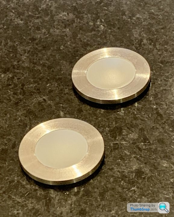
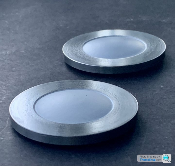
The domes are primed; they’ll be painted blue eventually.
I set the tool parallel to the bed:
And using more CAD:
Roughed the domes out:
Then using co-ordinates, approximated the profile:
Then using a combination of a dremel, files and abrasive paper:
Smoothed to shape:
Parted off using the home made rear post from earlier this year (worked great):
Then made a spacer ring and reversed in the chuck to turn and mill the inside details:
Took a few goes, but eventually I got a decent result:
The domes are primed; they’ll be painted blue eventually.
It’s been a while since I did anything on this for one reason or another (mainly a broken foot, then Covid, combined with a freezing cold garage over the winter).
I did some work on the first cylinder back in November, but didn’t get around to posting: First marked it out ready for drilling the valve chest holes:
Then put it back on the mandrel for machining:
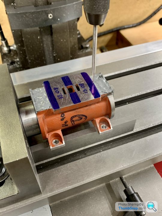
The cast flats either side of the valve faces were slightly too shallow to match the cylinder cap diameter, so I used JB Weld to add material, which was then milled back. The offset from each cylinder end also defined the edges of the valve face:
Then after finding the centre of the valve face, I offset the hole positions and drilled and tapped the 7BA holes:
Then this evening (6 months later!) I repeated the process on the other cylinder. I think I mentioned previously that there’s a slight asymmetry on this one in terms of a difference in length from valve port centre to cylinder ends. I made it a best fit, and at the end of the day it’s only about 0.6 mm out, so not obvious to the eye when everything is assembled. In fact by the time the gaskets are fitted, and considering selective assembly of the cylinder caps, the overall cylinder assemblies will probably be pretty much identical:
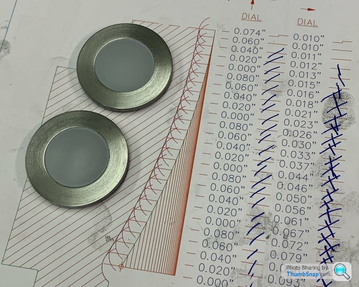
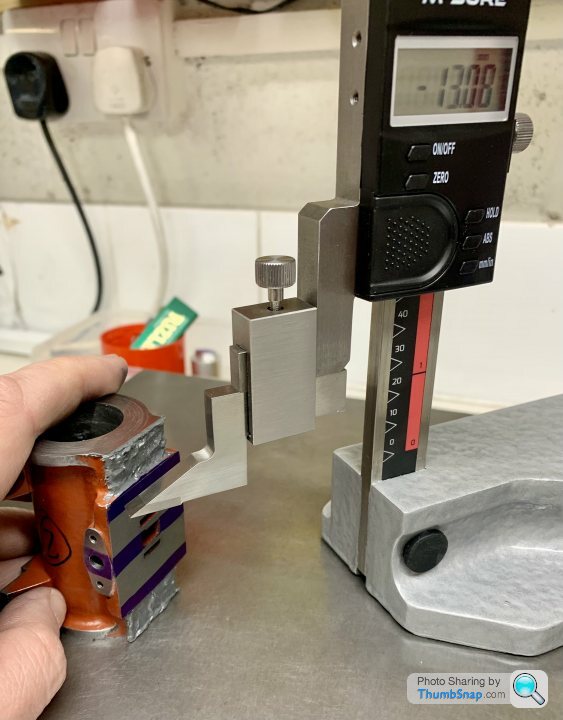
A quick check with the height gauge shows they’re pretty much spot-on identical in terms of valve face height:
And the end cap diameters now match the flats, so there’s no unsightly step:
Again, a matter of 10ths of a mm, but for some reason the castings were just undersized.
Still some minor cosmetic filing and filling to do, but pretty much there:
The bosses on the cylinder caps still need milling in the rotary table, but I think I’ll drill and tap the cylinder cap stud holes next, while the milling vice is set up square.
I did some work on the first cylinder back in November, but didn’t get around to posting: First marked it out ready for drilling the valve chest holes:
Then put it back on the mandrel for machining:
The cast flats either side of the valve faces were slightly too shallow to match the cylinder cap diameter, so I used JB Weld to add material, which was then milled back. The offset from each cylinder end also defined the edges of the valve face:
Then after finding the centre of the valve face, I offset the hole positions and drilled and tapped the 7BA holes:
Then this evening (6 months later!) I repeated the process on the other cylinder. I think I mentioned previously that there’s a slight asymmetry on this one in terms of a difference in length from valve port centre to cylinder ends. I made it a best fit, and at the end of the day it’s only about 0.6 mm out, so not obvious to the eye when everything is assembled. In fact by the time the gaskets are fitted, and considering selective assembly of the cylinder caps, the overall cylinder assemblies will probably be pretty much identical:
A quick check with the height gauge shows they’re pretty much spot-on identical in terms of valve face height:
And the end cap diameters now match the flats, so there’s no unsightly step:
Again, a matter of 10ths of a mm, but for some reason the castings were just undersized.
Still some minor cosmetic filing and filling to do, but pretty much there:
The bosses on the cylinder caps still need milling in the rotary table, but I think I’ll drill and tap the cylinder cap stud holes next, while the milling vice is set up square.
Cylinder cap stud holes today (all 40 of them!).
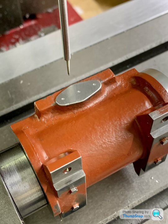
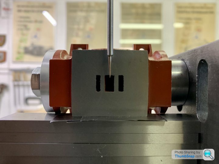
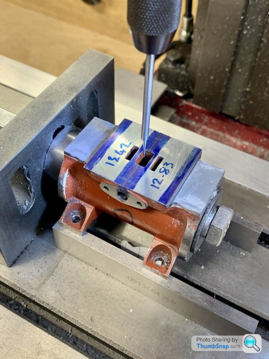
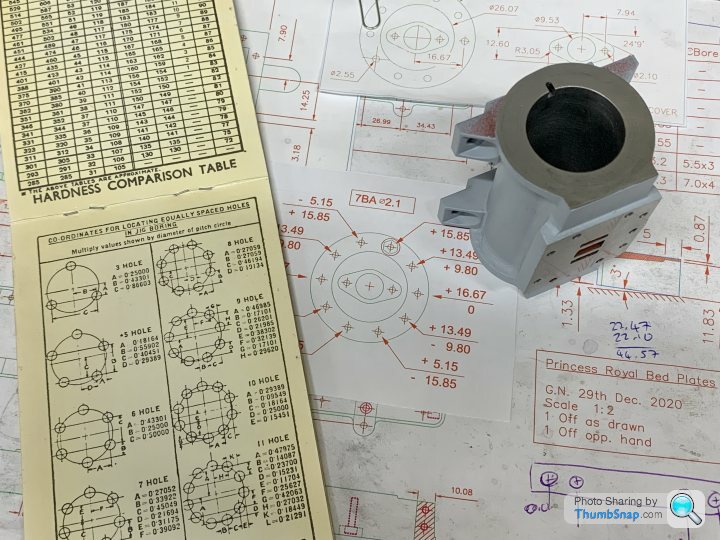
Checked the hole PCDs were right - I wanted the studs mid way between the cap o/ds and the central cast bits. This turned out to be slightly different from the plans. I got the co-ordinates from CAD, double-checked with the formula in my Zeus booklet:
Then, in the vice, checked the face for flatness:

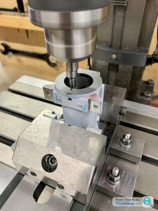
Got the centre of the face with the finder:
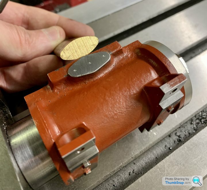
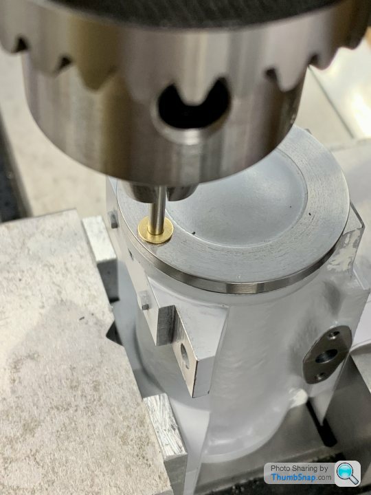
Double-checked the co-ordinates using a 7BA washer (looked OK):
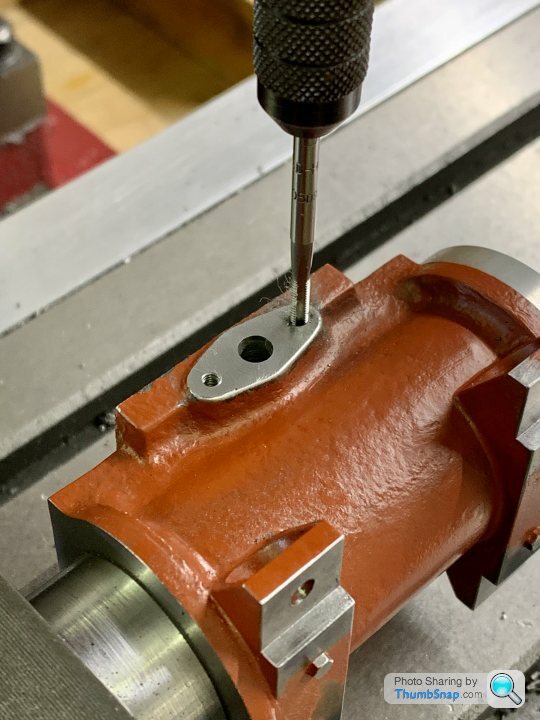
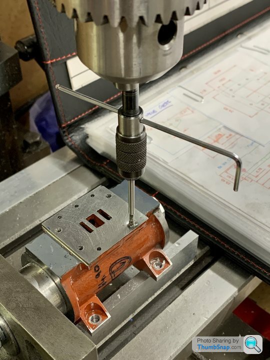
Then co-ordinate drilled the holes using the DRO. I went to 3mm deep, making sure I didn’t break through the flanges:
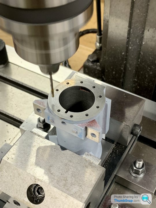
Tapped to 7BA using a plug tap:
Then went round each one by hand with a countersink to remove any burrs:
So a bit more progress:

Next job I think I’ll drill the valve chests.
Checked the hole PCDs were right - I wanted the studs mid way between the cap o/ds and the central cast bits. This turned out to be slightly different from the plans. I got the co-ordinates from CAD, double-checked with the formula in my Zeus booklet:
Then, in the vice, checked the face for flatness:
Got the centre of the face with the finder:
Double-checked the co-ordinates using a 7BA washer (looked OK):
Then co-ordinate drilled the holes using the DRO. I went to 3mm deep, making sure I didn’t break through the flanges:
Tapped to 7BA using a plug tap:
Then went round each one by hand with a countersink to remove any burrs:
So a bit more progress:
Next job I think I’ll drill the valve chests.
Gassing Station | Scale Models | Top of Page | What's New | My Stuff