Stuart 10V Vertical Steam Engine
Discussion


silverfoxcc said:
dr-gn
Myford and DRO
Got mine from Machine DRO, i did have some like yours on my WarcoWM16 but wasnt happy with them,
The M-DRO are a revalation if you get the Essien( need to check on the name) it even works out PCD and hole centres!!!
That one reads out to .0002 and the Lather one goes down to 0.00010
However this cured ,or i thought it did, the backlash, no more faffing about with watching the micro dial etc. BUT i was still getting duff measurements even though the digital read out was ok ,UNTIL one day noticed that the top slide had some play of about 10 thous Ahhh backlash, but no,after checking various bit it was a worn thread. got replacement from Myfords and now all is well again in the shed!
So tip to all check the worm and nut, it could be the best 100.00 you spend
Thanks for that. Big question is cost. TBH the cheap scales I put on the mill have been great so far. I don't expect them to last forever, but there's no doubt that I couldn't have got this far with the build without them.Myford and DRO
Got mine from Machine DRO, i did have some like yours on my WarcoWM16 but wasnt happy with them,
The M-DRO are a revalation if you get the Essien( need to check on the name) it even works out PCD and hole centres!!!
That one reads out to .0002 and the Lather one goes down to 0.00010
However this cured ,or i thought it did, the backlash, no more faffing about with watching the micro dial etc. BUT i was still getting duff measurements even though the digital read out was ok ,UNTIL one day noticed that the top slide had some play of about 10 thous Ahhh backlash, but no,after checking various bit it was a worn thread. got replacement from Myfords and now all is well again in the shed!
So tip to all check the worm and nut, it could be the best 100.00 you spend
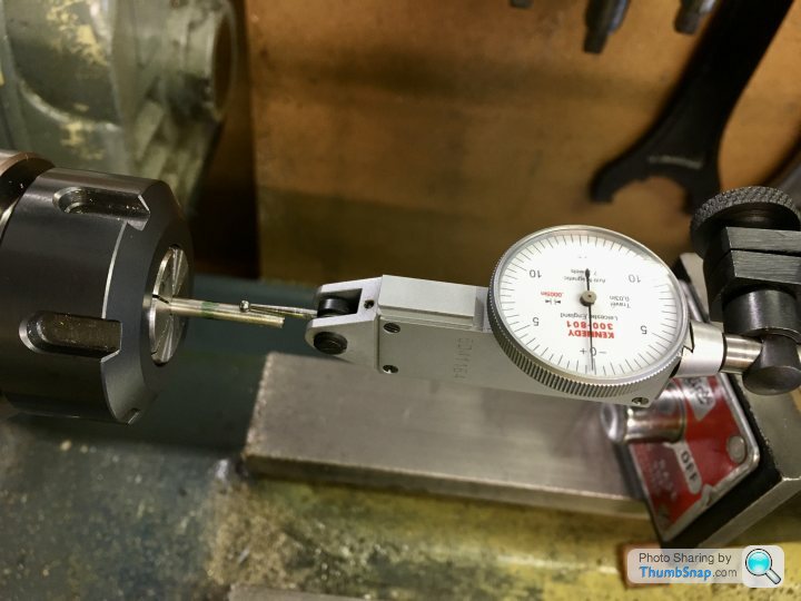
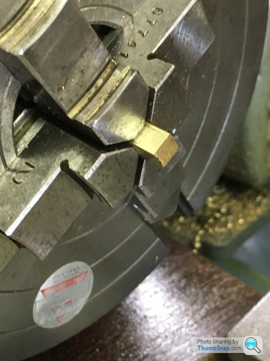
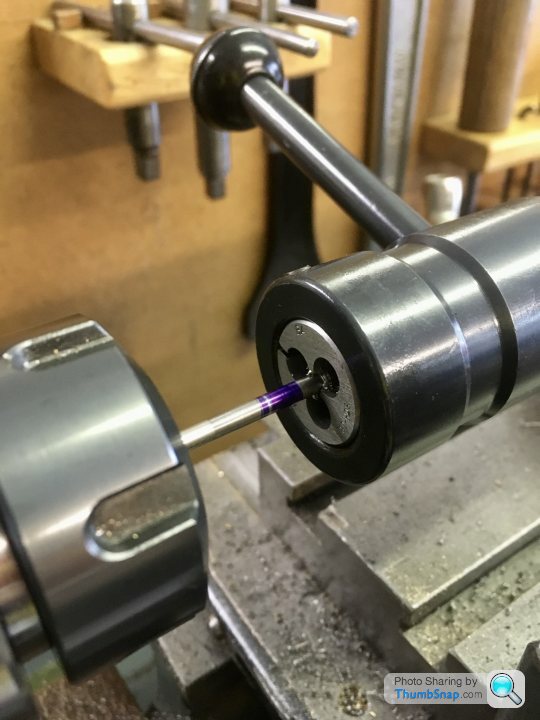
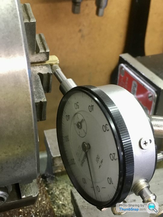
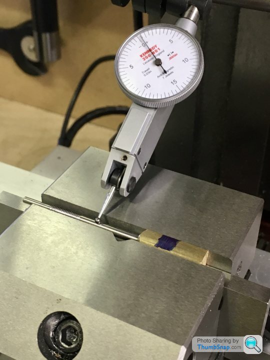
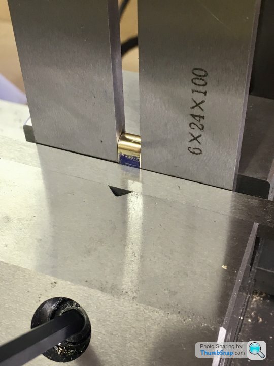
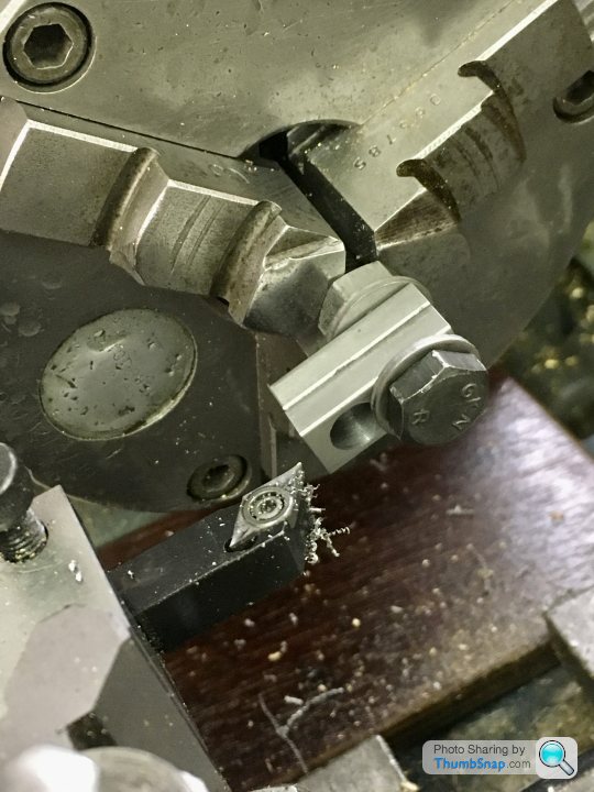
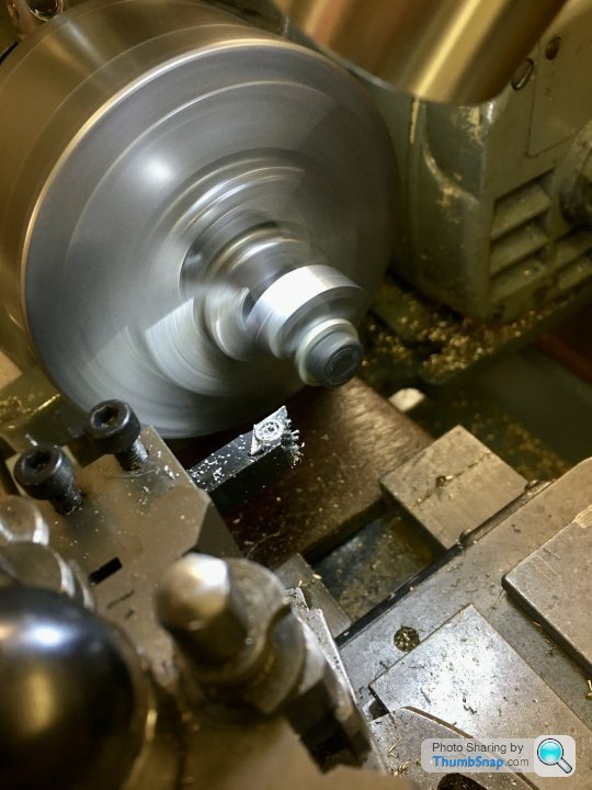
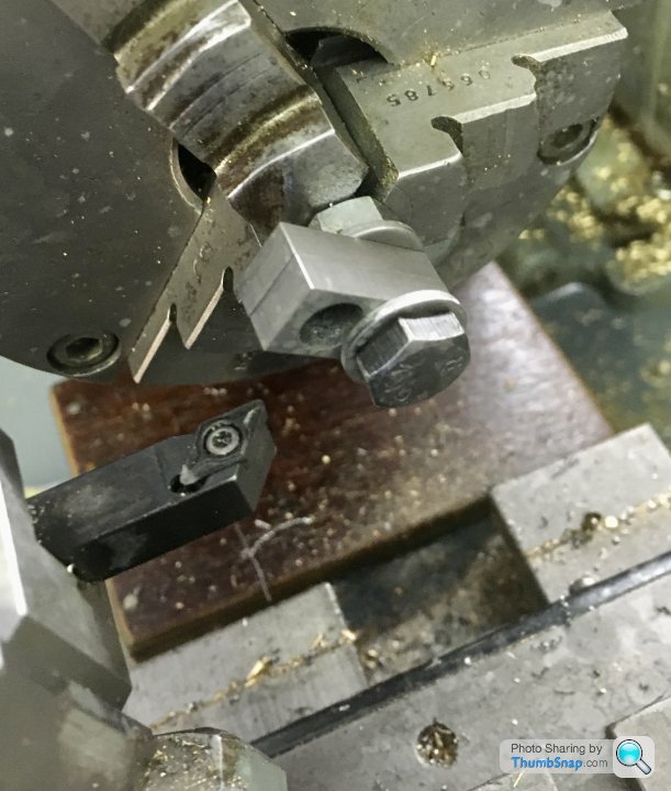
So tonight I re-set the scrap valve rod in the lathe and sawed the threaded end off. I found that putting it in a collet gave me 0.0015” runout, so I stuck with that rather than messing about with the split bush and 3-jaw chuck:
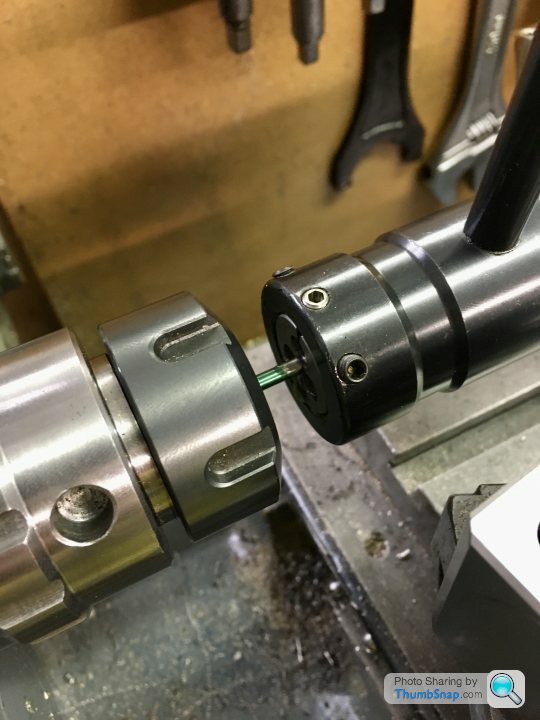
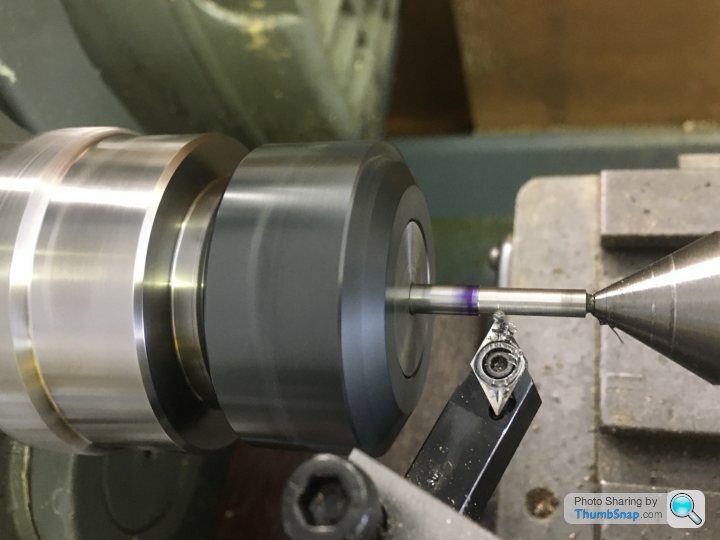
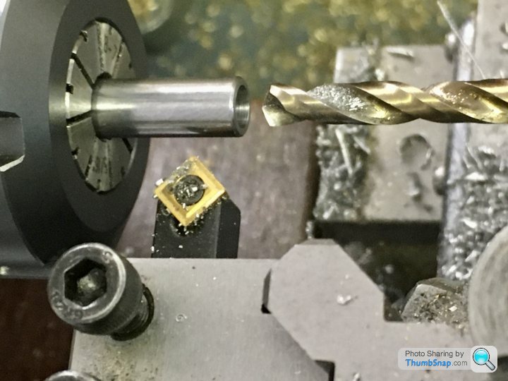
Centre drilled, and turned down to size with a DCGT insert, then tried the 5BA die. This time it worked. I needed to turn a pointed grub screw to open the die though:
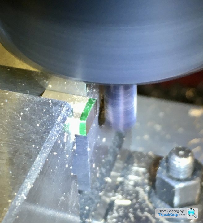
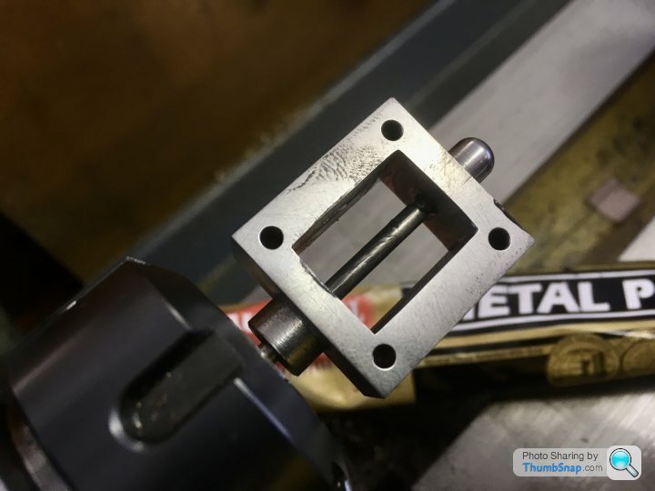
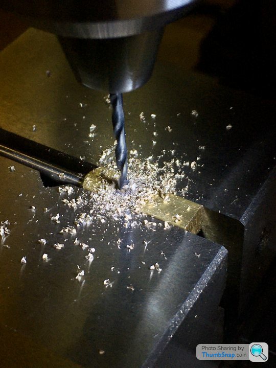
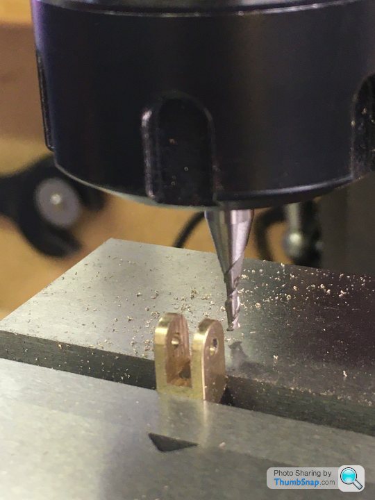
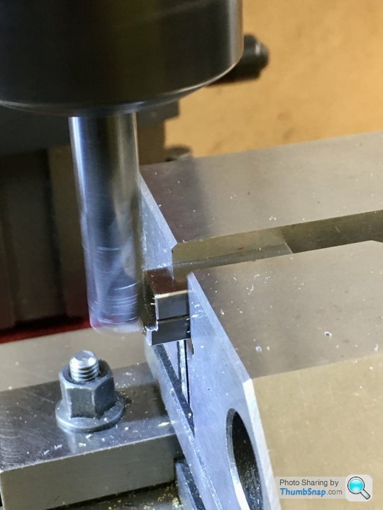
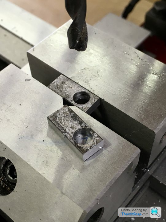
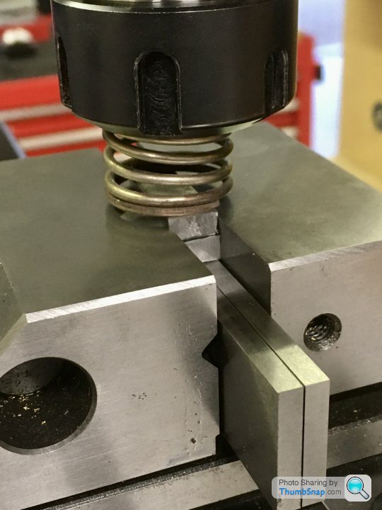
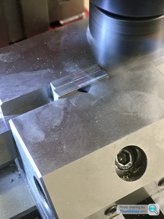
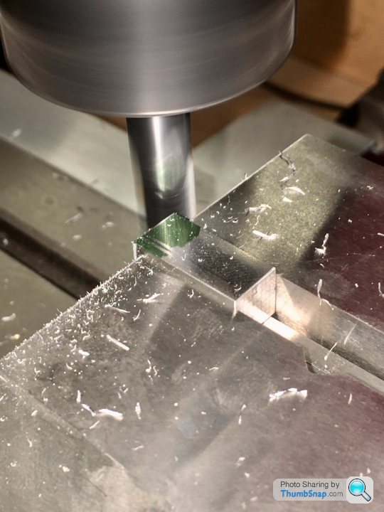
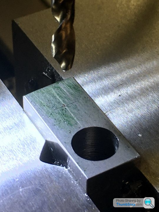
There was about 1mm to spare. Flushed with success, I milled the valve plate to size:
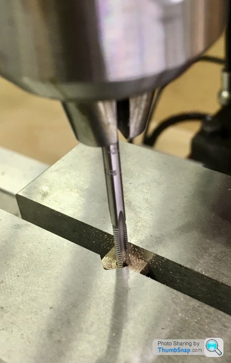
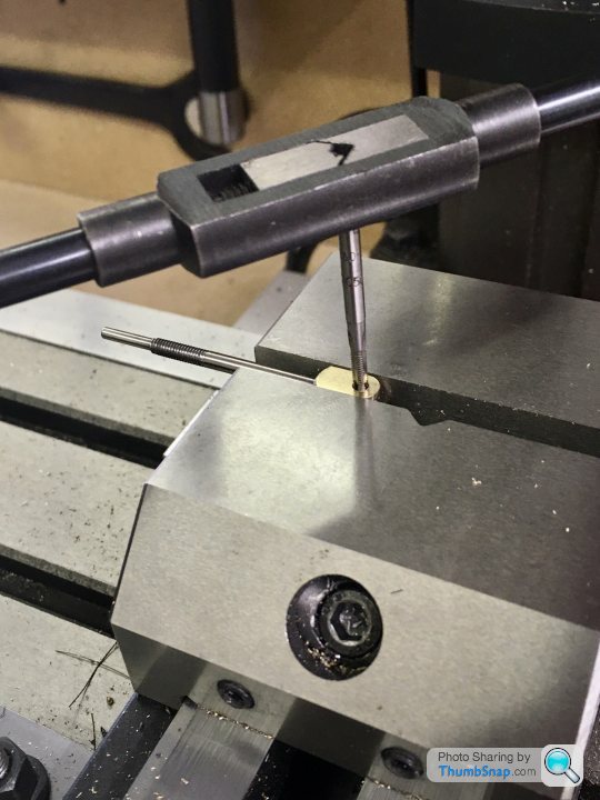
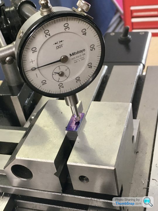
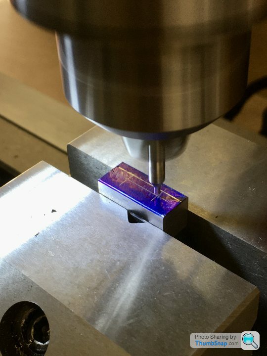
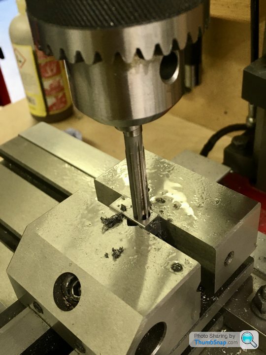
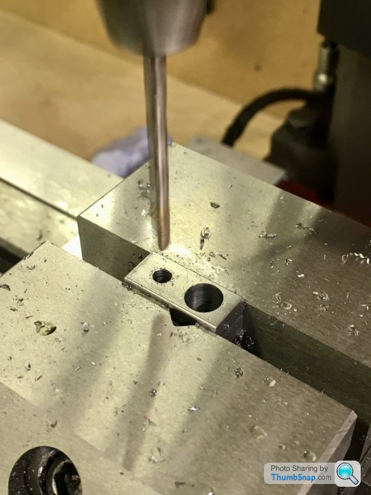
And drilled and tapped it after centering using the edge finder:
Fit in the rod was spot-on.
So then onto cleaning-up the valve Itself and the rest of the parts. The fit of the rod in the chest is pretty good, if a bit sticky at the top of the travel, but only in one orientation. Might need a bit of lapping or something to get it perfect. I think it’s Probably fine as it is though.
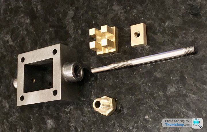
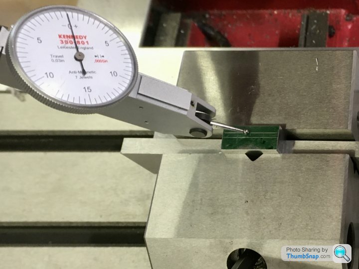
All seems to fit together well:
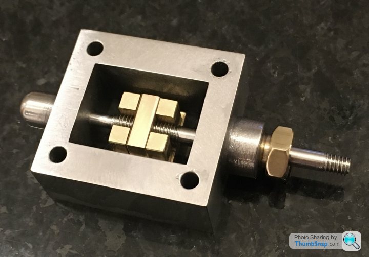
And I think the travel is OK for the ports too:
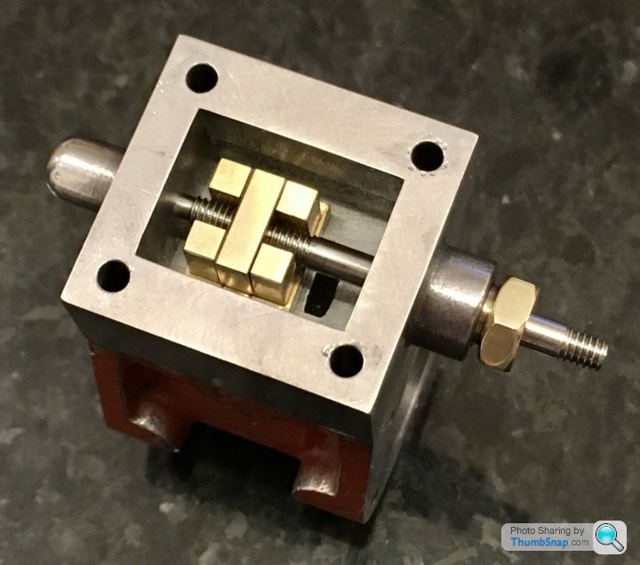
Just need to make sure the eccentric throw is spot-on.
Centre drilled, and turned down to size with a DCGT insert, then tried the 5BA die. This time it worked. I needed to turn a pointed grub screw to open the die though:
There was about 1mm to spare. Flushed with success, I milled the valve plate to size:
And drilled and tapped it after centering using the edge finder:
Fit in the rod was spot-on.
So then onto cleaning-up the valve Itself and the rest of the parts. The fit of the rod in the chest is pretty good, if a bit sticky at the top of the travel, but only in one orientation. Might need a bit of lapping or something to get it perfect. I think it’s Probably fine as it is though.
All seems to fit together well:
And I think the travel is OK for the ports too:
Just need to make sure the eccentric throw is spot-on.
silverfoxcc said:
dr-gn
I agree with the cost side, BUT since having them fitted on the 7 and the WM16 the scrap box is looking a lot emptier!! In fact my son often said i had enough bits in there to make another three engines!!
I did start off with the kit you have got, but when i saw the MDRO set up i was smitten!! start saving, you will not regret it
OK I'll look into it. I'm planning on building a Sturat Twin Victoria and Beam engine after the 10V. That should scratch the model engineering itch.I agree with the cost side, BUT since having them fitted on the 7 and the WM16 the scrap box is looking a lot emptier!! In fact my son often said i had enough bits in there to make another three engines!!
I did start off with the kit you have got, but when i saw the MDRO set up i was smitten!! start saving, you will not regret it
Thanks, the DRO looks like a production standard item. I’m still not really sure If I’d use anything other than the basic functions I’ve already got on the cheap mill versions. I just touch-on and zero the readouts and figure stuff out from there.
The biggest obstacle For me is going to be cost.
Cheers!
The biggest obstacle For me is going to be cost.
Cheers!
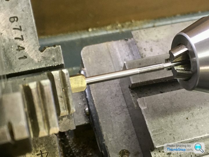
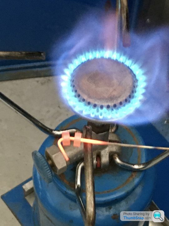
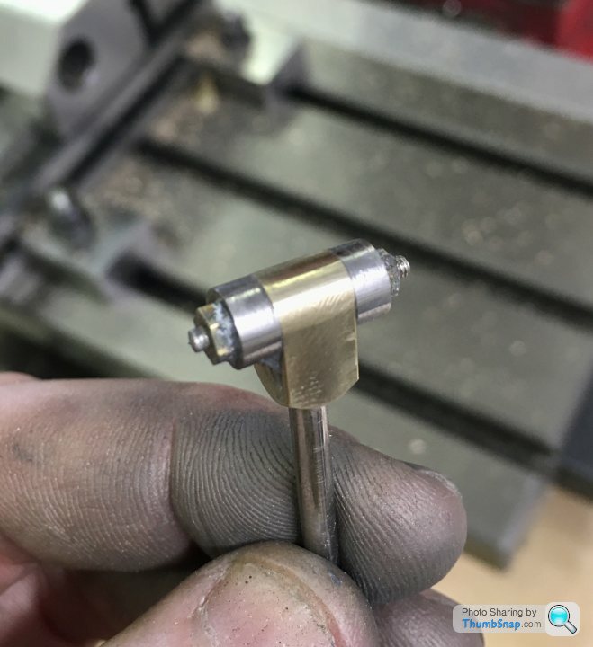
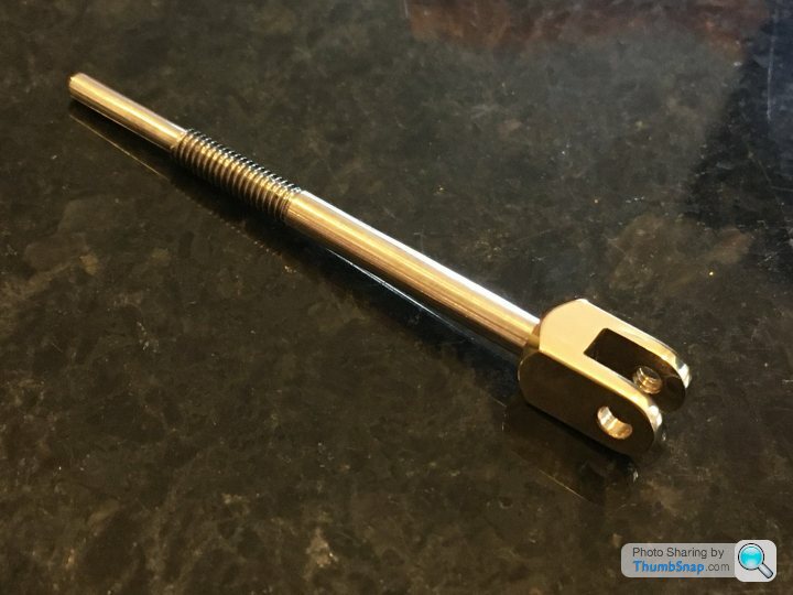
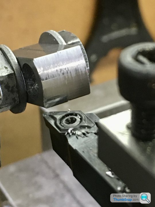
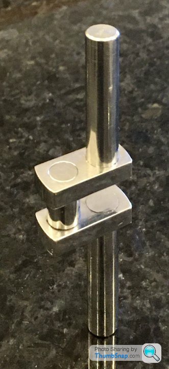
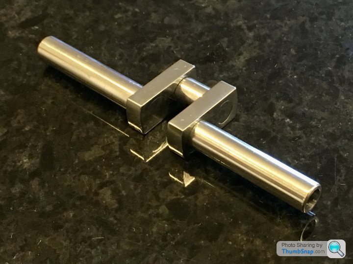
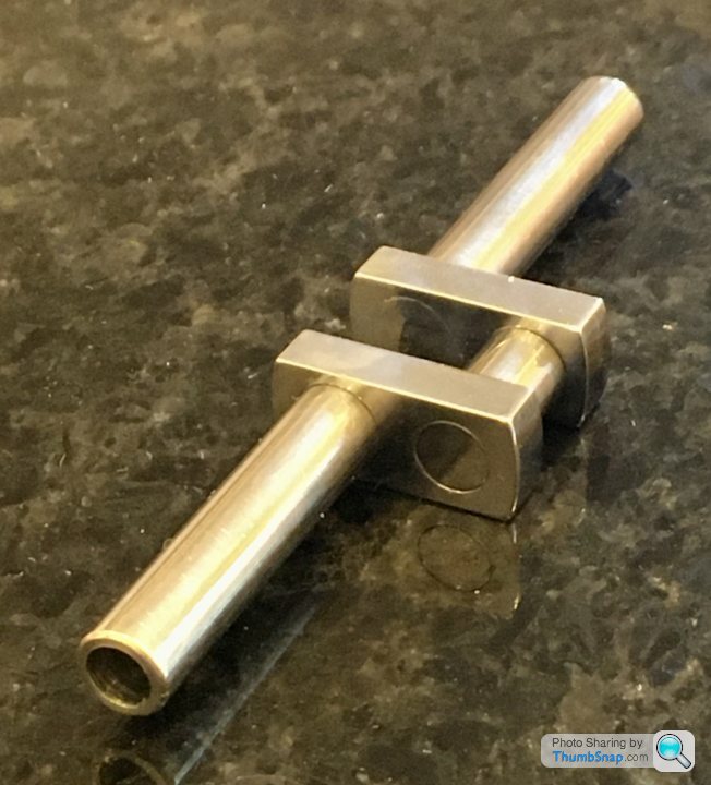
So I made a start on the valve rod fork end:
Full disclosure:
I chamfered the end, drilled, tapped and lightly screwed the rod in with Loctite. Then brought the tail stock chuck in, and gently nipped it around the end of the rod to keep it aligned while the Loctite set.
Turned the chuck Slowly by hand to make sure it was true, the Tailstock chuck grabbed, and twisted the end off the rod.
I think I may take a week off from this project.
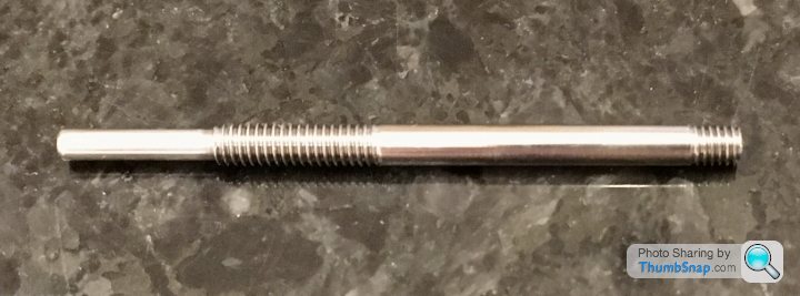
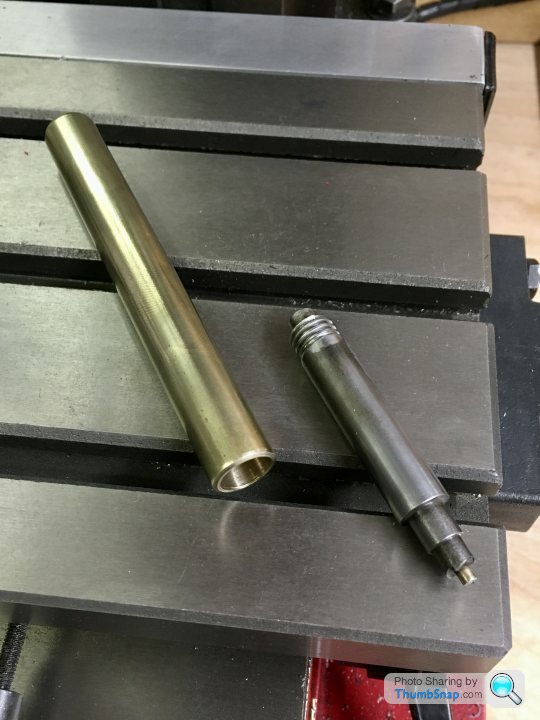
This morning I got a new rod (and some oilers and drain cocks from Stuart Models) and put it in the parts box. This evening took it out and started to machine it. Then test fitted it to the valve block and found I’d picked up the piston rod stock by mistake, which is too thick for the sealing gland. So started for the third time, this time on the right stock. Turned, lapped, threaded and re-set into the brass block. I didn’t turn the chuck this time. So back to where I was on Sunday.
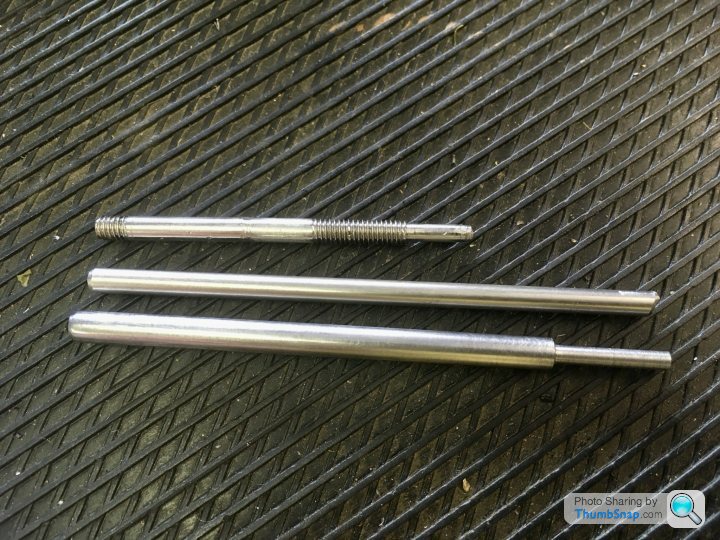
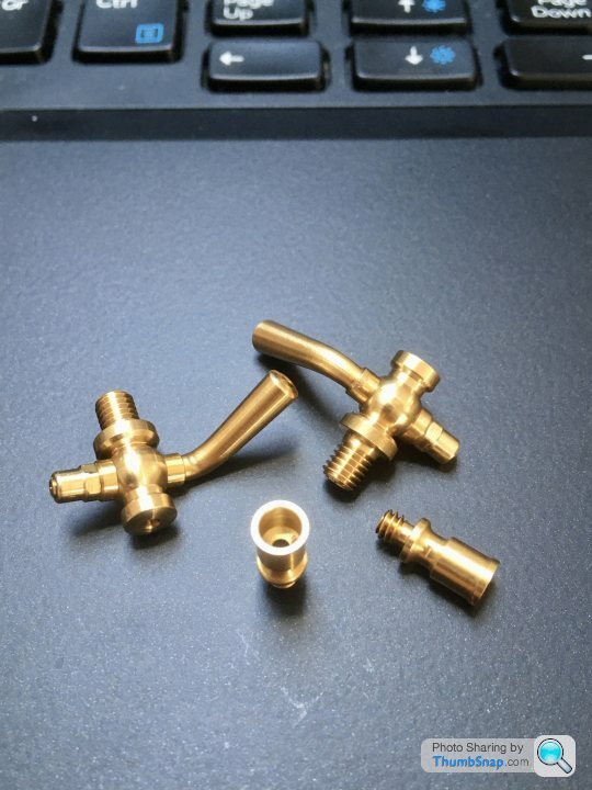
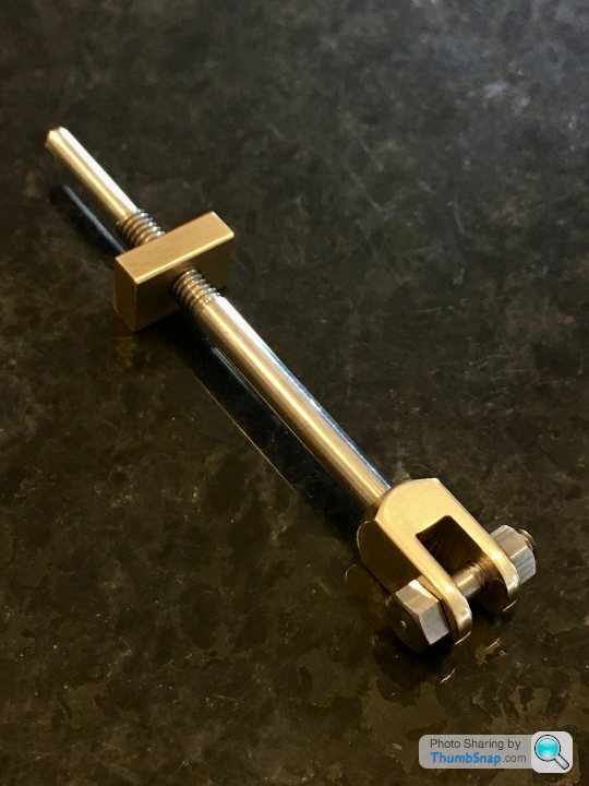
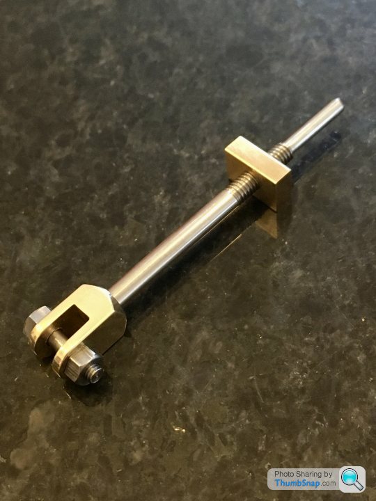
Thanks all, I’m really pleased how it turned out after all those setbacks.
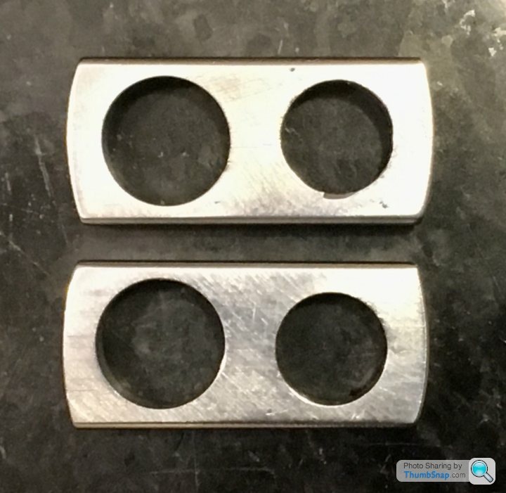
There are different types of filing button - I opted for the hardened and fixed type, but you can use un-hardened buttons that are loose fitted, and spin when the file touches them. You can also just use stainless, but I went with what made sense to me.
There are different types of filing button - I opted for the hardened and fixed type, but you can use un-hardened buttons that are loose fitted, and spin when the file touches them. You can also just use stainless, but I went with what made sense to me.
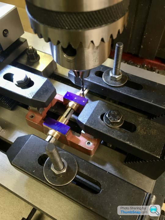
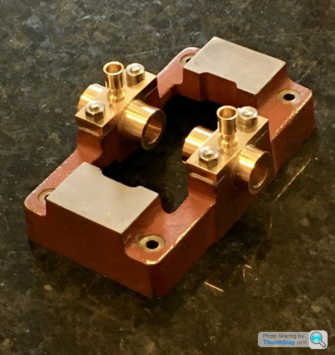
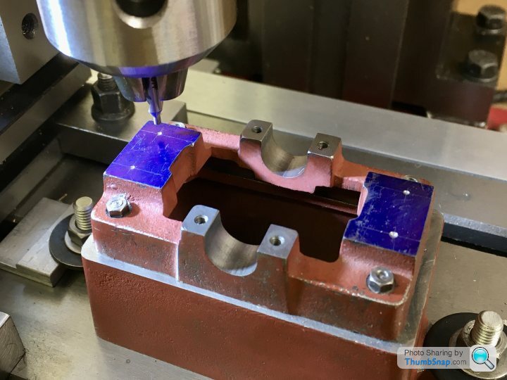
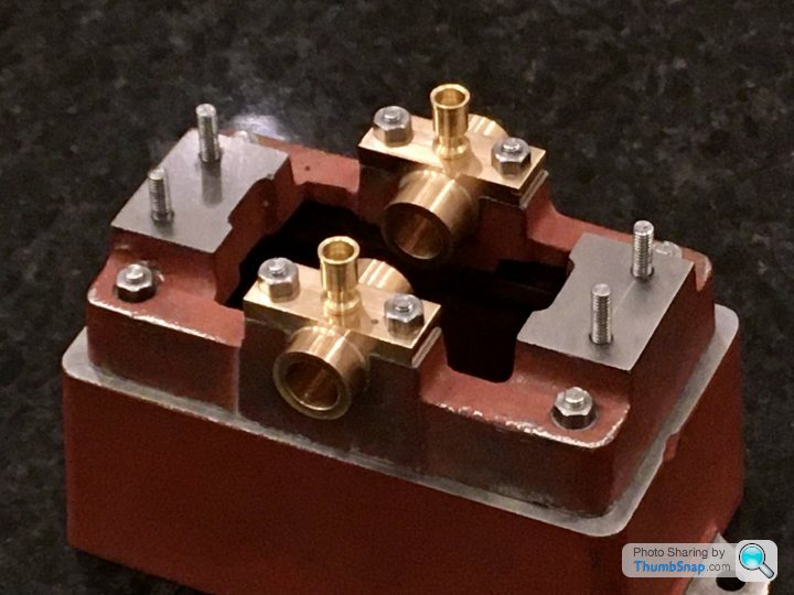
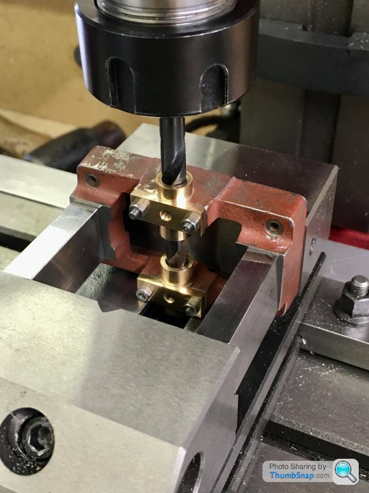
I got a bit distracted with other projects recently, but today I fitted the main bearings to the sole plate.
I set it up so that the plate would remain fixed to the mill bed when the bearings were un-clamped. This was so I could drill with tapping drills, clearance drills or whatever, then remove the blocks and go back to exactly the same co-ordinates for tapping.
I used the plate flange edges as datums, because that’s where the nuts and oilers will be viewed relative to. If there was an error in how central the bores are, and I took the bore centreline as a datum, the whole lot would look off.
Started by drilling through everything with a tapping drill:
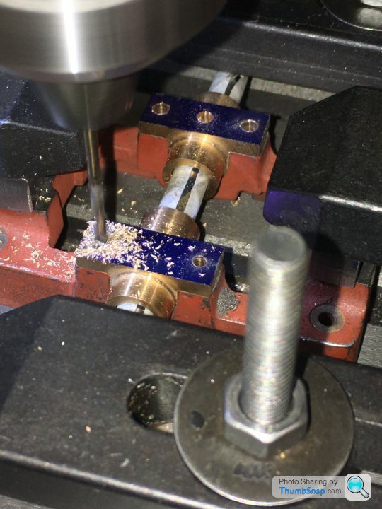
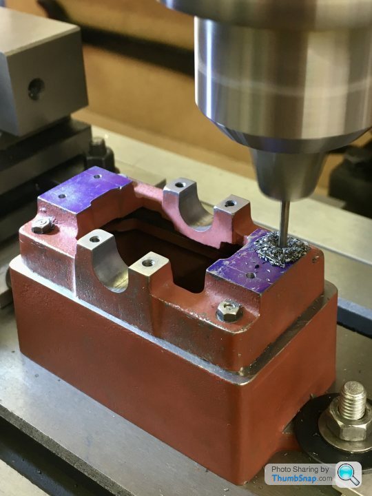
Then opening up just the flanges to clearance:
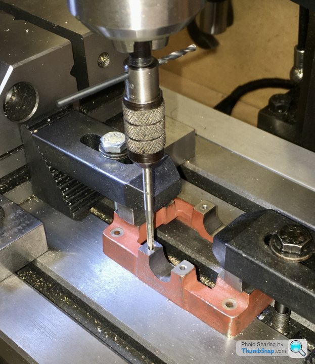
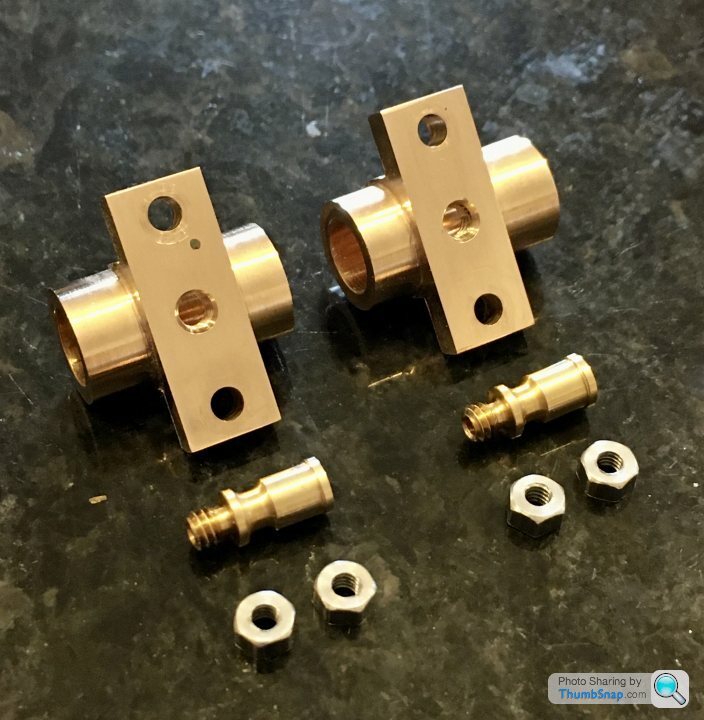
Then removed the bearings and tapped the sole plate:
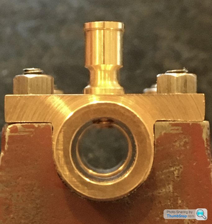
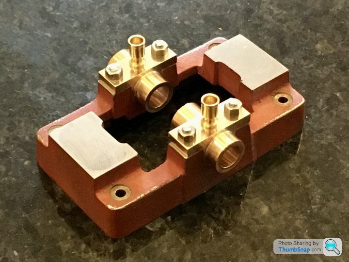
Then re-fitted the bearings using studs and nuts, and tapped the oiler holes:
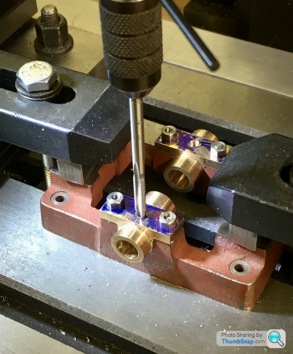
I’m not sure if I should have gone all the way through to the bore with the tapping drill, but too late now. The oilers themselves have a constriction in them. I’ll have to find some fibre washers because they protrude into the journal. Good job I spotted that - could easily have caused some confusion/damage on test assembly:
I didn’t notice that the bearing mount holes were relieved under the sole plate. It looks like everything is on the right place though, so I’m confident the blocks were the right size, and were aligned properly in their pockets:
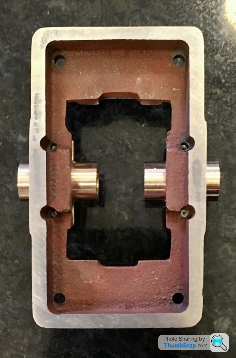
So that’s that:
I set it up so that the plate would remain fixed to the mill bed when the bearings were un-clamped. This was so I could drill with tapping drills, clearance drills or whatever, then remove the blocks and go back to exactly the same co-ordinates for tapping.
I used the plate flange edges as datums, because that’s where the nuts and oilers will be viewed relative to. If there was an error in how central the bores are, and I took the bore centreline as a datum, the whole lot would look off.
Started by drilling through everything with a tapping drill:
Then opening up just the flanges to clearance:
Then removed the bearings and tapped the sole plate:
Then re-fitted the bearings using studs and nuts, and tapped the oiler holes:
I’m not sure if I should have gone all the way through to the bore with the tapping drill, but too late now. The oilers themselves have a constriction in them. I’ll have to find some fibre washers because they protrude into the journal. Good job I spotted that - could easily have caused some confusion/damage on test assembly:
I didn’t notice that the bearing mount holes were relieved under the sole plate. It looks like everything is on the right place though, so I’m confident the blocks were the right size, and were aligned properly in their pockets:
So that’s that:
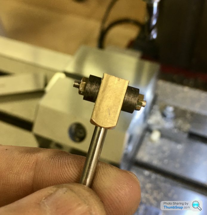
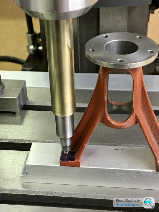
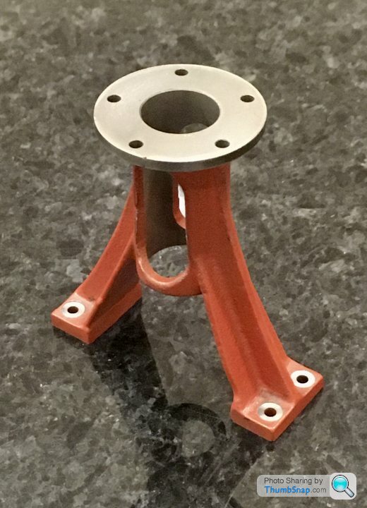
Next job I think will be to mount the standard to the sole plate. I’ve had to make an extension for the spot-face tool I made previously. I drilled and turned some brass bar to be a fit on the spot-face tool shank, and put a thread at the end to secure:
Seems to run true enough for the job.
Seems to run true enough for the job.
After a lot of pondering I started on fitting the standard to the sole plate. I wanted the cylinder bore axis to precisely intersect the crankshaft axis.
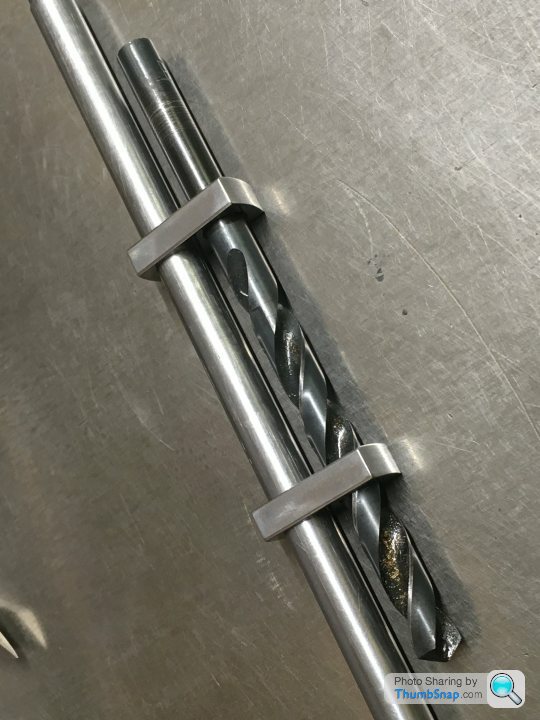
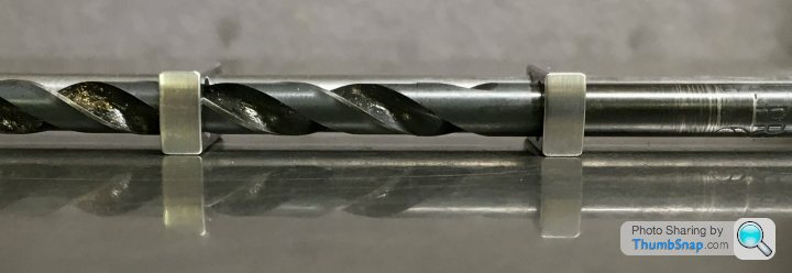
To hold the sole plate, it seemed easiest to fit it to the box-bed and secure that to the x-axis. I aligned the sole plate to the axis by touching-on the sides of the standard pads. I also fitted the bearings and slid a drill through. By touching-on each side I could easily find the axis, and zero the x DRO Then halved the widths off the standard pads to get the y centreline and zero the DRO:
It was then a very simple job to co-ordinate drill and tap the four holes:
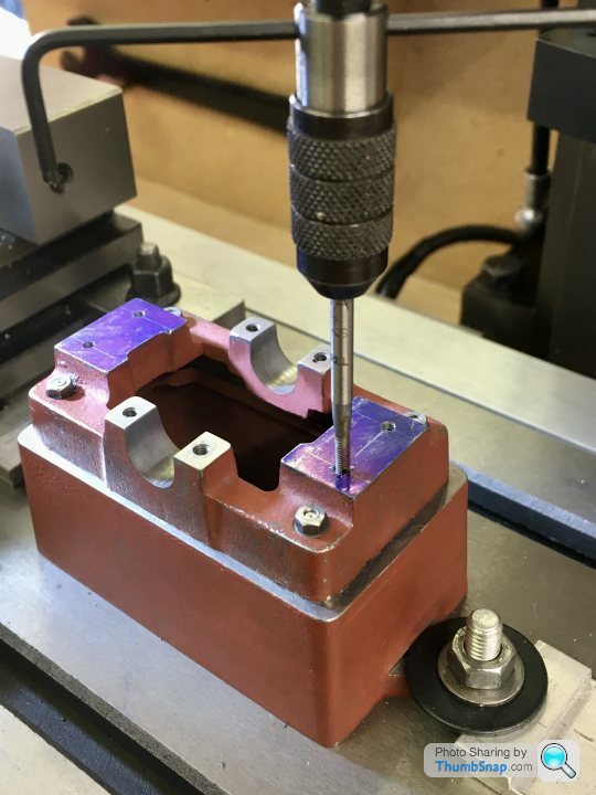
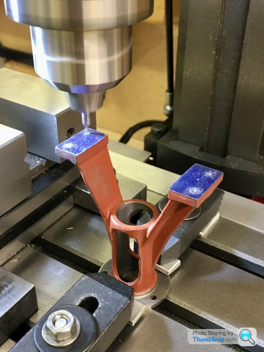
Then the standard itself. I mounted it upside down to make drilling easier. Then aligned the foot pads along the x-axis with the edge finder:
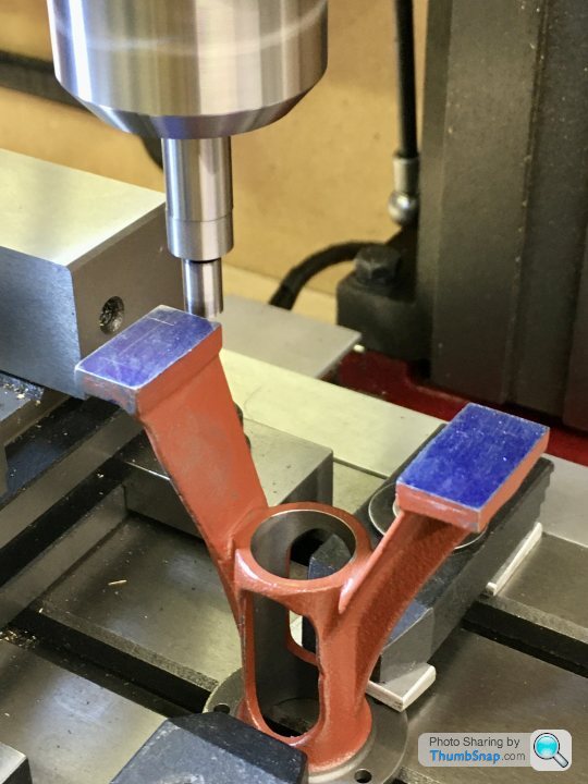
Then got the centre of the slider bore:
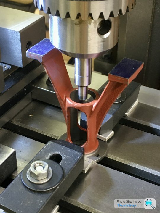
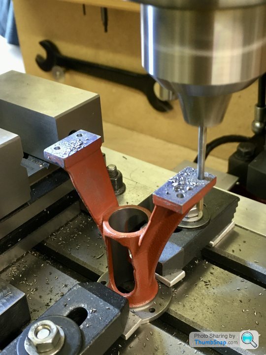
Zeroed the x and y DROs on the centre axis, and again drilled to the same co-ordinates as the sole plate holes:
Then inverted it to use the extended spot-face tool. I aligned it by eye to the holes:
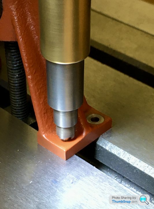
Still works perfectly despite it being covered in surface rust:
The sole plate with studs fitted - I messed up and put a deep score across one of the faces by not fully retracting the tap holder...
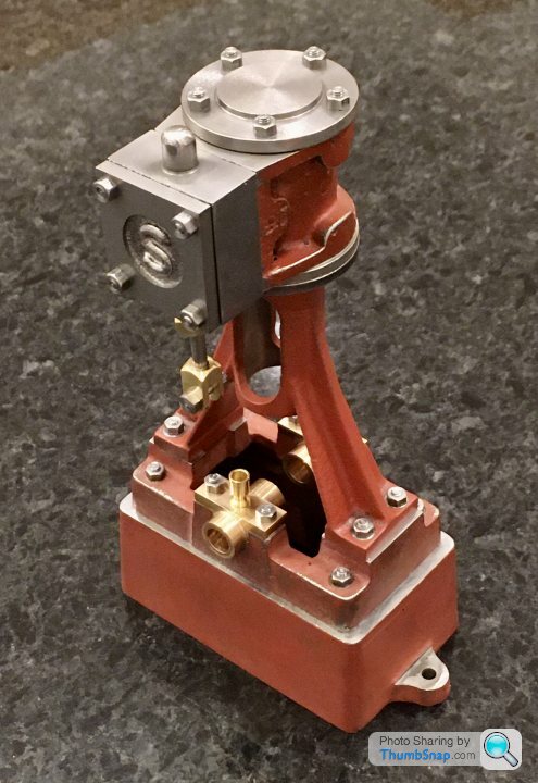
Quick test assembly of everything so far seemed to indicate it’s all square:
Might have a go at the connecting rod next.
To hold the sole plate, it seemed easiest to fit it to the box-bed and secure that to the x-axis. I aligned the sole plate to the axis by touching-on the sides of the standard pads. I also fitted the bearings and slid a drill through. By touching-on each side I could easily find the axis, and zero the x DRO Then halved the widths off the standard pads to get the y centreline and zero the DRO:
It was then a very simple job to co-ordinate drill and tap the four holes:
Then the standard itself. I mounted it upside down to make drilling easier. Then aligned the foot pads along the x-axis with the edge finder:
Then got the centre of the slider bore:
Zeroed the x and y DROs on the centre axis, and again drilled to the same co-ordinates as the sole plate holes:
Then inverted it to use the extended spot-face tool. I aligned it by eye to the holes:
Still works perfectly despite it being covered in surface rust:
The sole plate with studs fitted - I messed up and put a deep score across one of the faces by not fully retracting the tap holder...
Quick test assembly of everything so far seemed to indicate it’s all square:
Might have a go at the connecting rod next.
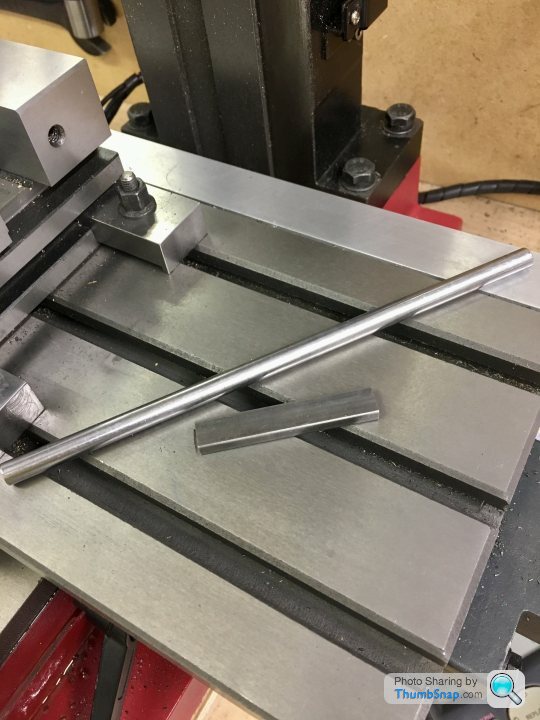
I thought I’d have a go at the crankshaft next, because the connecting rod needs to be fitted to it in terms of width, and the bearings also need shortening to suit it.
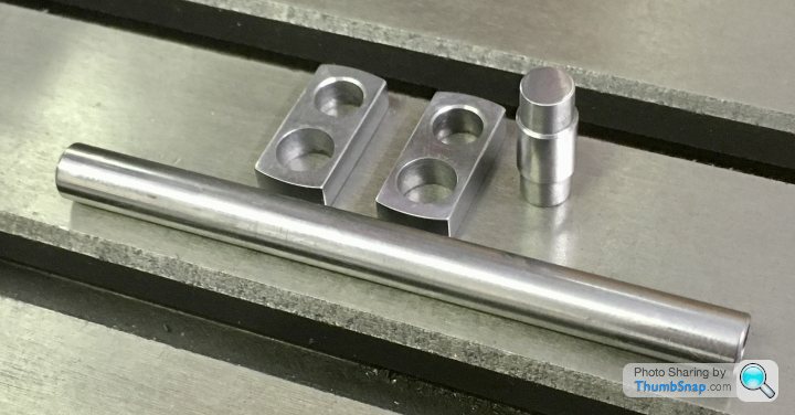
Started with the bar, and steel strip:
Cut the bar in half and soft soldered it together, so that the drilled holes will be perfectly aligned:
Then milled to the correct overall web length:
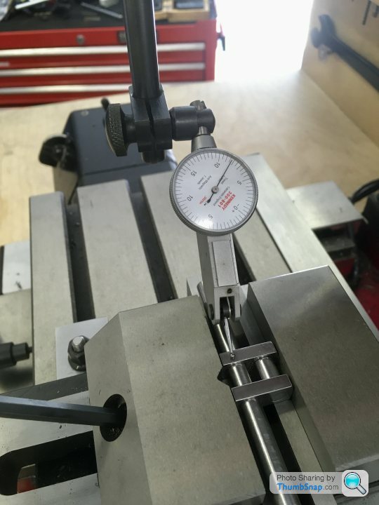
Put in the vice again and checked it for level:
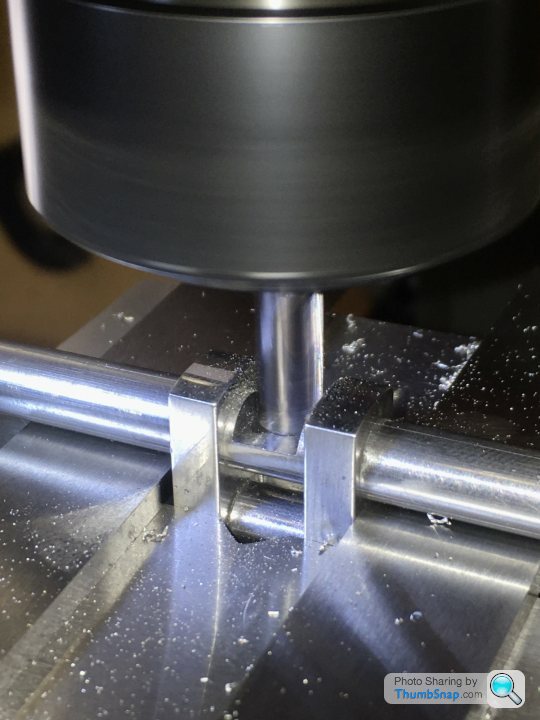
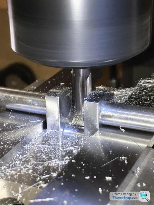
Centre drilled:
Then drilled to pre-ream size...but the solder broke:
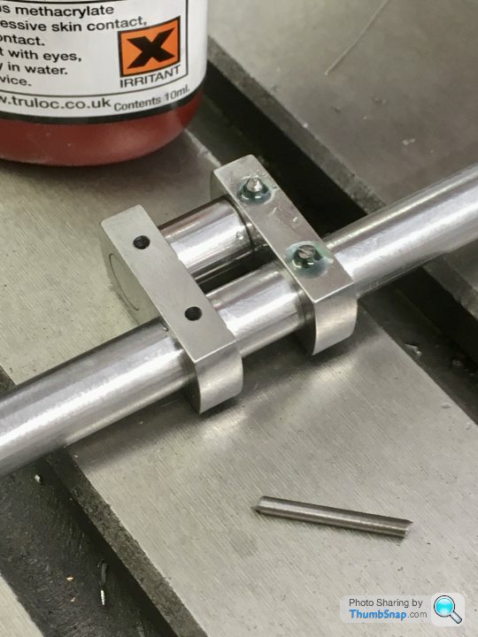
So I bonded them with retainer, using the pre-ream drill to align the halves (and clamped them in the vice to keep them square). Then reamed for the shaft:
And drilled for the crank pin:
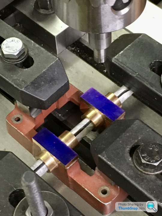
It turned out that the crank web end radii are centred on the opposite holes, so I clamped them with a close fitting bolt and nut, and turned the radii in the lathe:
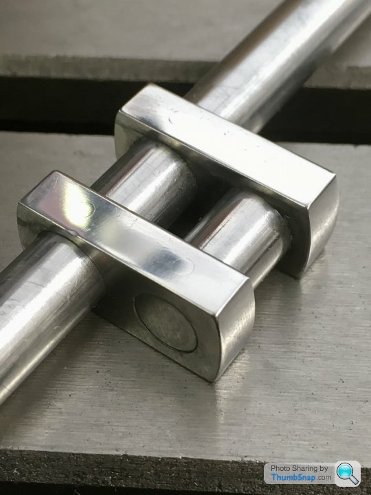
The hole axes appear to be parallel in two planes, and the webs normal to them and parallel to each other:
But unfortunately the crank pin holes are offset in the webs to one side:
I must have made an error in getting the centreline of the web assembly when drilling.
Unfortunately, despite the error having no effect on the function of the crankshaft, I’ll have to get some more material and start again I guess.
Started with the bar, and steel strip:
Cut the bar in half and soft soldered it together, so that the drilled holes will be perfectly aligned:
Then milled to the correct overall web length:
Put in the vice again and checked it for level:
Centre drilled:
Then drilled to pre-ream size...but the solder broke:
So I bonded them with retainer, using the pre-ream drill to align the halves (and clamped them in the vice to keep them square). Then reamed for the shaft:
And drilled for the crank pin:
It turned out that the crank web end radii are centred on the opposite holes, so I clamped them with a close fitting bolt and nut, and turned the radii in the lathe:
The hole axes appear to be parallel in two planes, and the webs normal to them and parallel to each other:
But unfortunately the crank pin holes are offset in the webs to one side:
I must have made an error in getting the centreline of the web assembly when drilling.
Unfortunately, despite the error having no effect on the function of the crankshaft, I’ll have to get some more material and start again I guess.
rolster said:
Or you might just adapt the current webs design and make them individual. Just reshape them symetrically, there are no counterweights on the webs and its not going to effect the running of the unit. Presentation wise the "updated design" would not look out of place as long as the modifications are symetrical. the drawings doesn't give a tollerance for the webs outer dimensions (from memory) so as long as you have enough web thickness around the main journals and the crank pin journal then you should be fine. Mind you my father keeps reminding me, my 10V still needs finishing off (about 90% complete) from when i left off it around 30 years ago! keep up the good work as i do enjoy reading your threads.
Thanks,yes - someone on the ME forum suggesting profiling them to have concentric radii concentric with the drillings at each end, and tapered sides.I think that profiling them like that would actually take longer - for me - to do accurately than making new ones. Not decided yet - after all I've not got any spare material left. A good thing about having arallel sides is that you can use them as an alignment datum for assembly, by placing them on a surface plate.
rolster said:
As always the builders choice is what matters, not us interlopers. I look forward to seeing how you progress on this build.
I appreciate the suggestions, and I actually think a lobed crankshaft would look better than the standard version. For a first model though, I'm conscious that by reprofiling the webs, I'd be compensating for an error. I'd rather try to get it right as per the plans this time. I 'phoned a metal procurement company just up the road and they have half a metre of 3/8" x 3/16" bright mild steel strip for £1. So for that, I'll try again.
So...crank webs part deux. The spare material from Stuart Models is £10.46 (delivered) for a 2” length. My local materials company supplied my 1/2 metre for £1.20. I’ll not comment further on that,
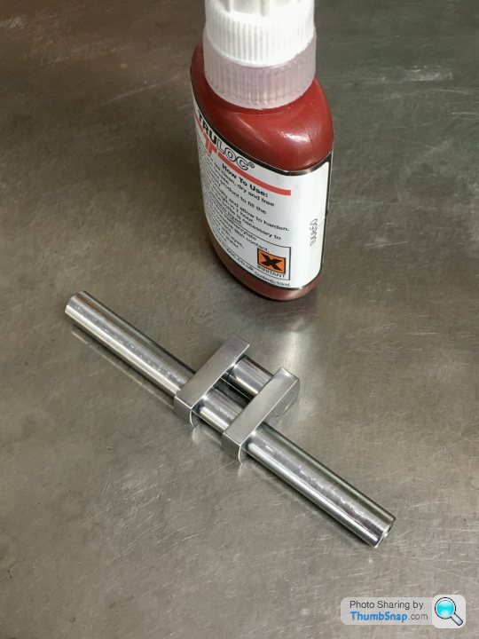
First job - Loctite two pieces together:
Then fly-cut the edges to clean them up a fraction to be perfectly flat and parallel:
Mill the ends to be square:
Mark out, then put in the vice and check for level:
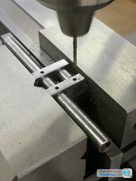
Co-ordinate drill/ream the holes, having first used the edge finder to get the datums. This time I used the marking out as a double-check:
Then used the nut and bolt method to turn the end radii:
Then machined the main shaft. Not sure why there’s a hole in one end, but it’s on the drawing:

Main components ready for assembly:
And Loctited together:
Now re-set in the vice and check for level:
And co-ordinate drilled the pin holes:
Tapped the Loctite-coated pins in with a hammer, and flatted and polished back:
Then put back in the vice, dropped onto a pair of parallels. The sacrificial part of the main shaft was then carefully milled away:
That completed the crankshaft:
So second time around it worked fine.
First job - Loctite two pieces together:
Then fly-cut the edges to clean them up a fraction to be perfectly flat and parallel:
Mill the ends to be square:
Mark out, then put in the vice and check for level:
Co-ordinate drill/ream the holes, having first used the edge finder to get the datums. This time I used the marking out as a double-check:
Then used the nut and bolt method to turn the end radii:
Then machined the main shaft. Not sure why there’s a hole in one end, but it’s on the drawing:
Main components ready for assembly:
And Loctited together:
Now re-set in the vice and check for level:
And co-ordinate drilled the pin holes:
Tapped the Loctite-coated pins in with a hammer, and flatted and polished back:
Then put back in the vice, dropped onto a pair of parallels. The sacrificial part of the main shaft was then carefully milled away:
That completed the crankshaft:
So second time around it worked fine.
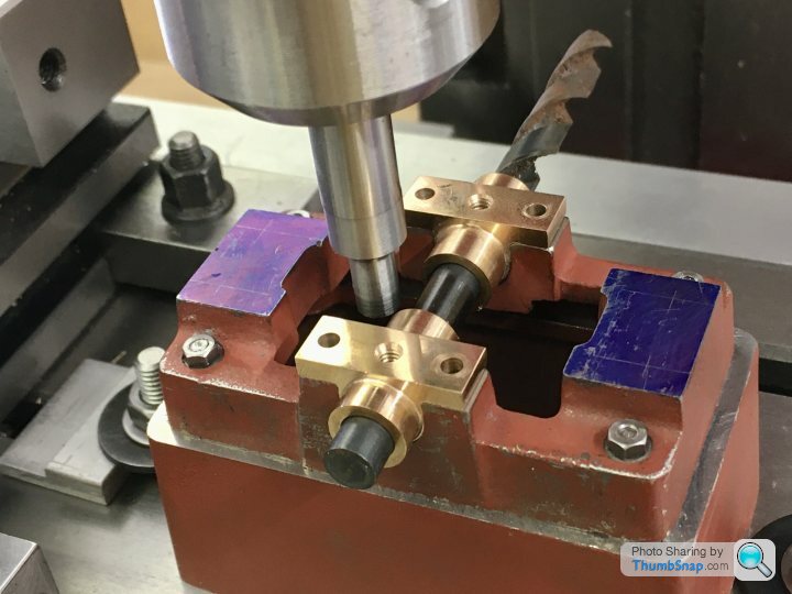
Then straight on to fitting the crankshaft to the bearings.
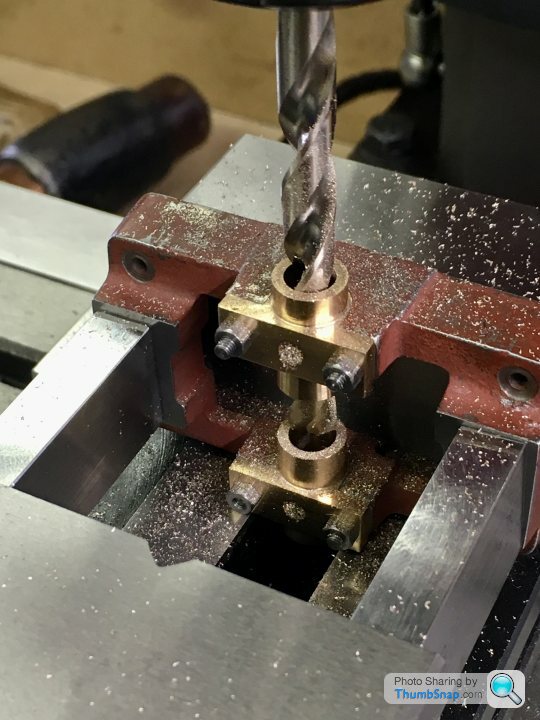
Began by aligning the assembled bearings into the vice using the drill I used to bore them undersized:
Then substituted it with the pre-ream drill:
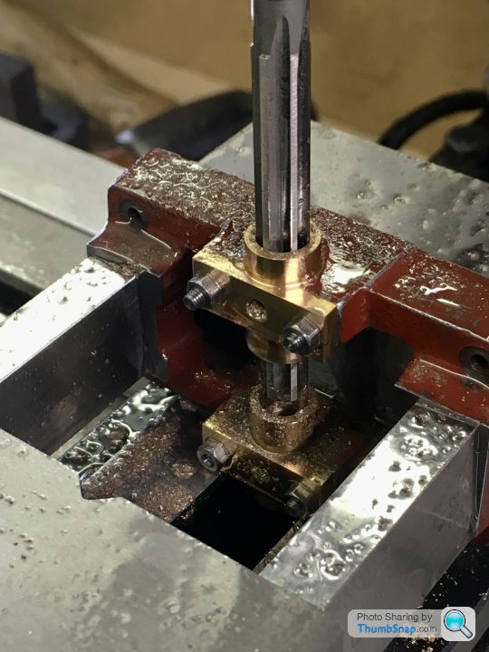
Then the reamer:
Then sized the bearing thrust faces by trial and error turning in the lathe. I should probably have used an expanding mandrel, but the collet chuck seemed to work well enough. The crank pin is now central in the sole plate (let’s hope it’s also aligned correctly under the cylinder bore axis):
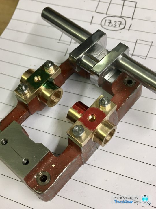
It all fitted together well enough:
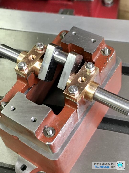
No side play, and after test-fitting the flywheel, it spins as smooth as silk:
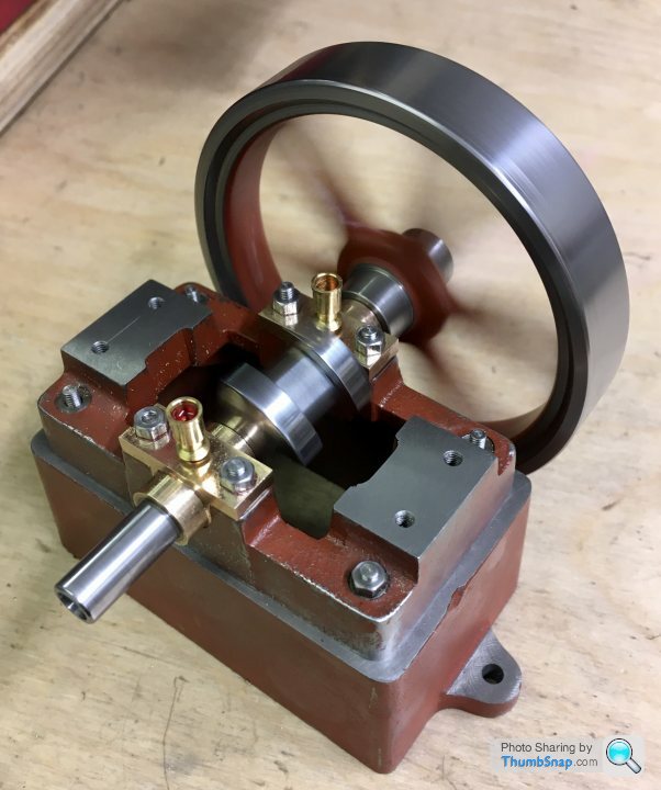
I’m pretty satisfied with today’s progress.
Began by aligning the assembled bearings into the vice using the drill I used to bore them undersized:
Then substituted it with the pre-ream drill:
Then the reamer:
Then sized the bearing thrust faces by trial and error turning in the lathe. I should probably have used an expanding mandrel, but the collet chuck seemed to work well enough. The crank pin is now central in the sole plate (let’s hope it’s also aligned correctly under the cylinder bore axis):
It all fitted together well enough:
No side play, and after test-fitting the flywheel, it spins as smooth as silk:
I’m pretty satisfied with today’s progress.
Gassing Station | Scale Models | Top of Page | What's New | My Stuff