Stuart Twin Victoria (Princess Royal) Mill Engine
Discussion


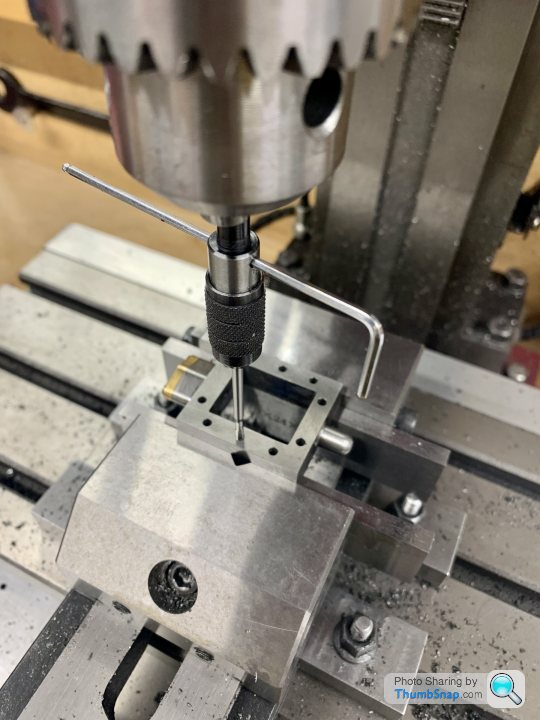
Spent some time today drilling the valve chests. They are handed, and have a top and a bottom, but still look very similar, so easy to make a mistake…
Started by putting them in the mill and checking they’re flat:
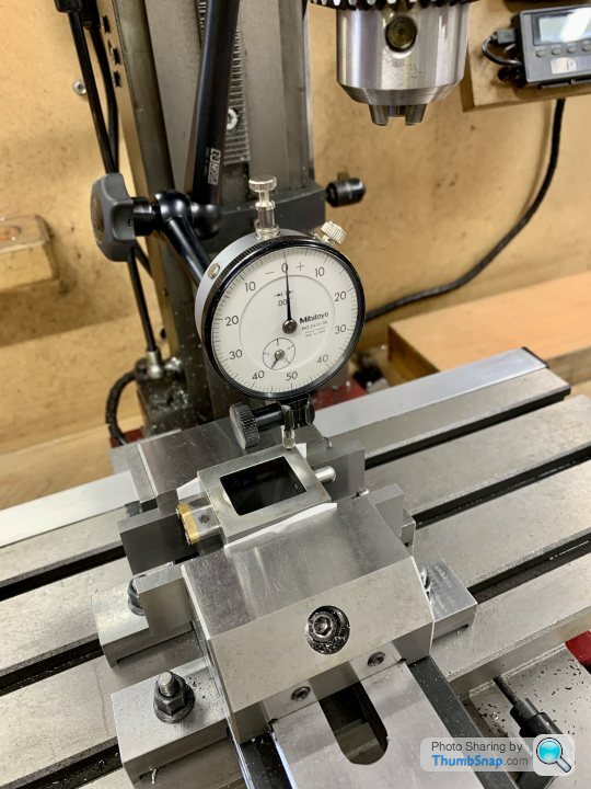
Then got the centre with the edge finder:
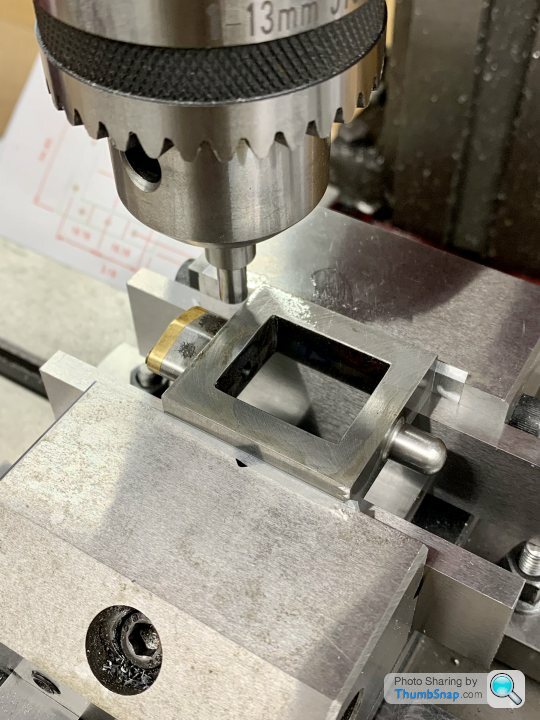
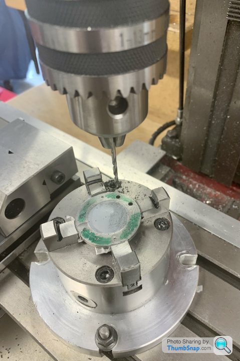
Then co-ordinate drilled with a centre drill. I skipped this step for the second one because the centre drill seemed to leave a central pip. I later realised I’d had this discussion before, and bought a stub drill (I think that’s what it’s called). I think Covid has a lot to answer for in terms of occasional brain fog:
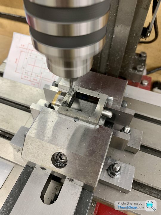
Through-drilled to 7BA clearance:
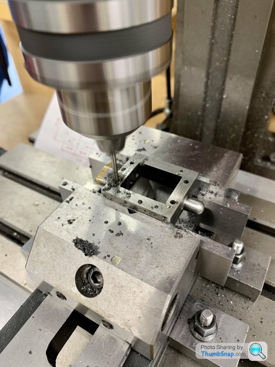
I thought the drill might wander on contact, hence why I initially used centre drilling, but in the event it was fine.
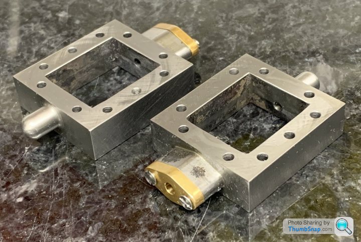
Then drilled and tapped one 7BA hole, over where the steam inlet will be:
Finished by hand countersinking all the holes.
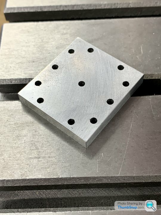
The drilled chests:
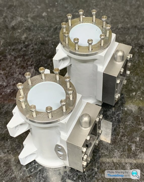
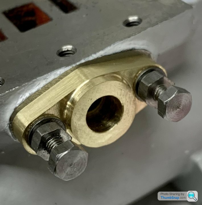
Test fitted to the cylinders using bolts:
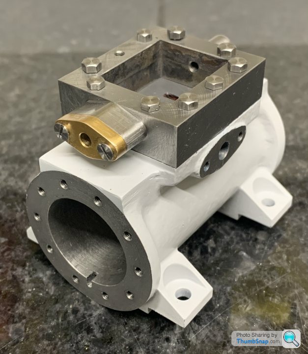
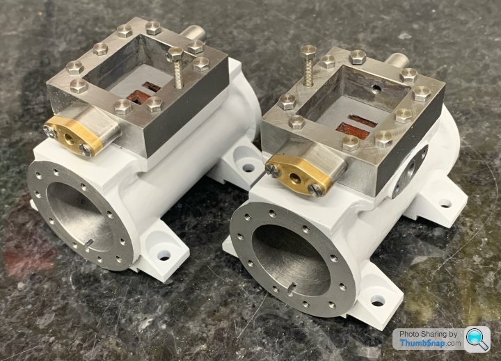
So far so good. The only thing left to do on the chests is to drill the steam inlet holes, and the mount holes for the inlet boxes.
Started by putting them in the mill and checking they’re flat:
Then got the centre with the edge finder:
Then co-ordinate drilled with a centre drill. I skipped this step for the second one because the centre drill seemed to leave a central pip. I later realised I’d had this discussion before, and bought a stub drill (I think that’s what it’s called). I think Covid has a lot to answer for in terms of occasional brain fog:
Through-drilled to 7BA clearance:
I thought the drill might wander on contact, hence why I initially used centre drilling, but in the event it was fine.
Then drilled and tapped one 7BA hole, over where the steam inlet will be:
Finished by hand countersinking all the holes.
The drilled chests:
Test fitted to the cylinders using bolts:
So far so good. The only thing left to do on the chests is to drill the steam inlet holes, and the mount holes for the inlet boxes.


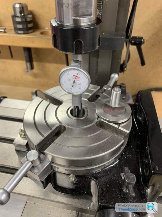
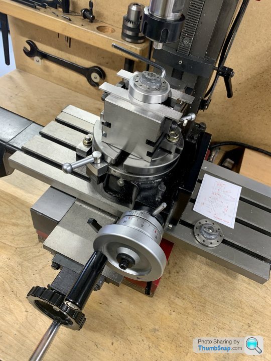
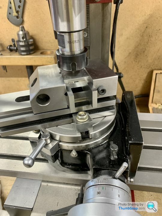
Set up the covers in the mill to get the gland clamp holes correctly lined up dead horizontal:
Centred the r/t to give zero runout:
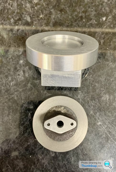
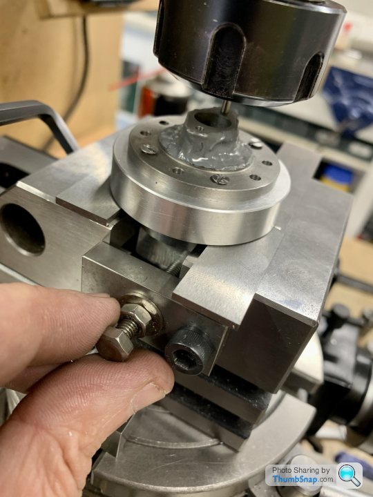
Mounted the chuck, and placed a cover and a tight fitting spigot I turned from aluminium. The spigot was then clamped into the collet chuck with the 4-jaw chuck loose, and then nipped up:
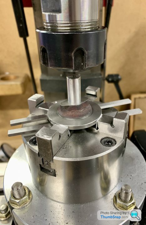
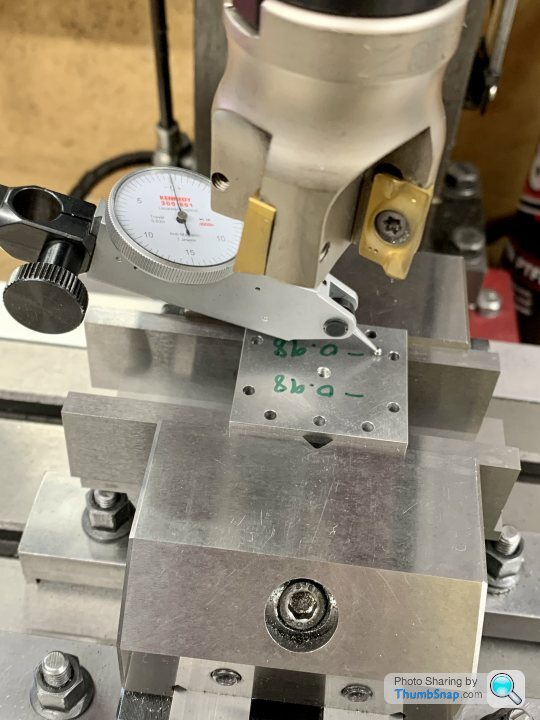
This should have got we very close to everything concentric, but try as I might, a 0.0095” runout remained:
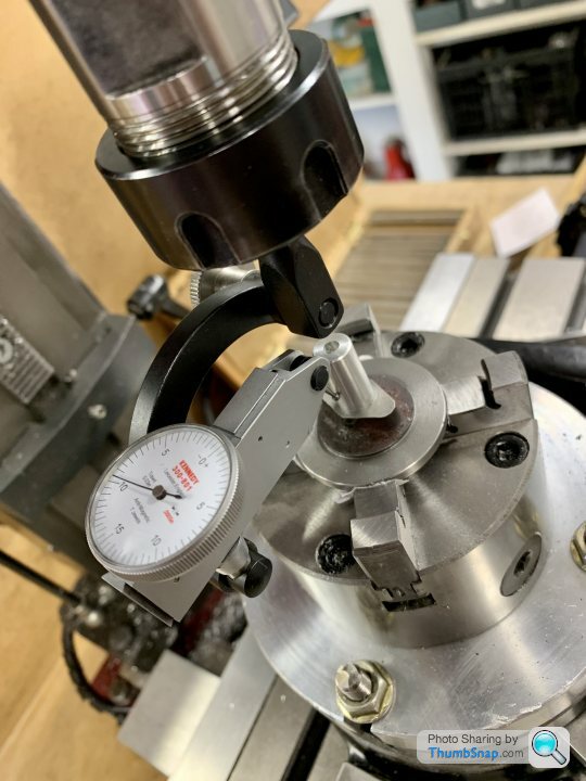
Even by adjusting the 4-jaw on the rotary table, I couldn’t get better than 0.0095” according to the dti mounted and revolved in the spindle.
Anyway, it was then a simple matter to fit the gland template and rotate the r/t until the mounting holes were in a line, 8mm offset each way in x:

Then with the r/t table locked, drilled all the holes using the DROs:
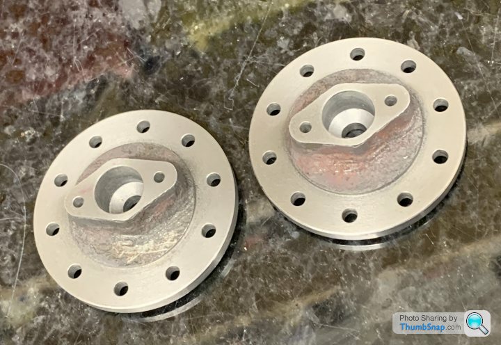
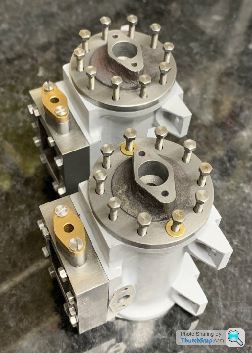
At the end of the day, they both fit, the holes are aligned and the bosses should be in their optimum positions for the profile milling:
Next job is to drill and tap the milling fixture hole array, then mill the boss profiles.
Centred the r/t to give zero runout:
Mounted the chuck, and placed a cover and a tight fitting spigot I turned from aluminium. The spigot was then clamped into the collet chuck with the 4-jaw chuck loose, and then nipped up:
This should have got we very close to everything concentric, but try as I might, a 0.0095” runout remained:
Even by adjusting the 4-jaw on the rotary table, I couldn’t get better than 0.0095” according to the dti mounted and revolved in the spindle.
Anyway, it was then a simple matter to fit the gland template and rotate the r/t until the mounting holes were in a line, 8mm offset each way in x:
Then with the r/t table locked, drilled all the holes using the DROs:
At the end of the day, they both fit, the holes are aligned and the bosses should be in their optimum positions for the profile milling:
Next job is to drill and tap the milling fixture hole array, then mill the boss profiles.
Simpo Two said:
I am in awe of this project. Being a woodworker, metal is too bloody hard to cut and makes all my tools go blunt!
I could make the above in wood, but 3mm aluminium is about as far as I go in metal. Oh and I can turn brass, if it's the soft kind. Brass rod yes, but brass sheet nearly wrecked my lathe
Thanks! If your lathe is a metalworking lathe with the right tooling it should be ok on most model engineering type metals. My lathe is a Myford ML7, and is fine for this kind of stuff. The milling machine is a Chinese thing and not great - not half as nice to use as the Myford. It does the job but you have to know it’s limitations and work around them - like often just taking very small cuts to stop horrible noises.I could make the above in wood, but 3mm aluminium is about as far as I go in metal. Oh and I can turn brass, if it's the soft kind. Brass rod yes, but brass sheet nearly wrecked my lathe
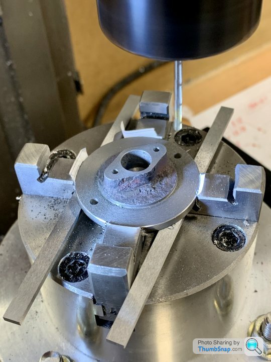
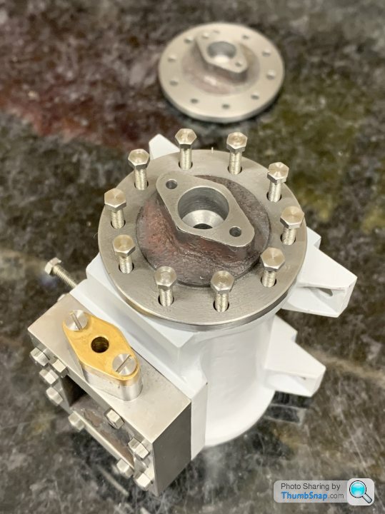
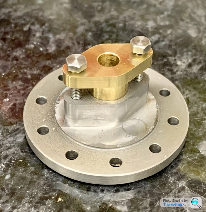
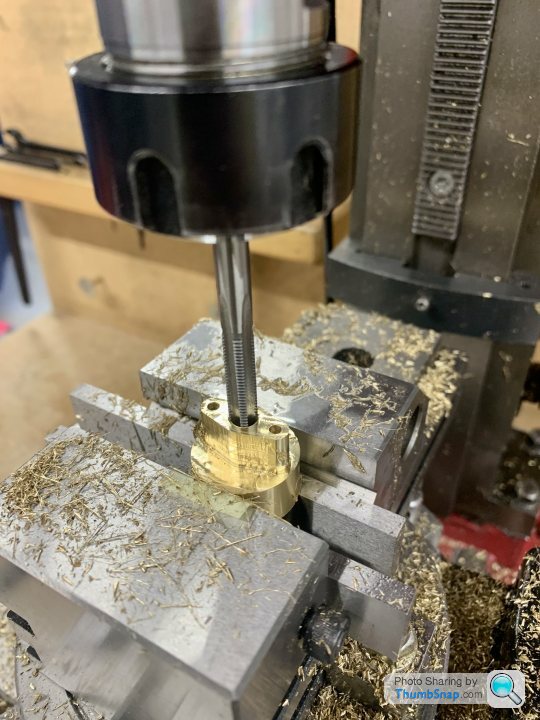
Drilled and tapped the cover fixture, and fitted the first cover:
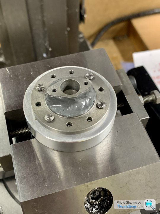
I’ve put JB Weld around the boss as a bit of insurance against running off the casting where it’s a bit marginal.
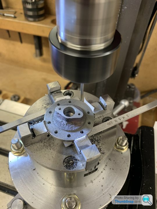
Then double-checked the alignment of the R/T, mounted the vice and centred on the job while everything was still loose:
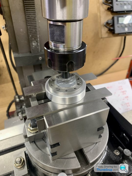
Then put a smaller drill in the collet chuck to offset the job left and right and set the end stops:
This will allow me to move the cover to automatically re-centre on the end holes to mill the end radii, while maintaining the same cut depth.
All ready:
Then remembered I’ve not yet made the brass blanks for the gland collars…doh!
I’ve put JB Weld around the boss as a bit of insurance against running off the casting where it’s a bit marginal.
Then double-checked the alignment of the R/T, mounted the vice and centred on the job while everything was still loose:
Then put a smaller drill in the collet chuck to offset the job left and right and set the end stops:
This will allow me to move the cover to automatically re-centre on the end holes to mill the end radii, while maintaining the same cut depth.
All ready:
Then remembered I’ve not yet made the brass blanks for the gland collars…doh!
julian64 said:
Bit that confuses me is the amount of work they put you to regarding the castings
why have the cylinder castings separate to the feet, or for that matter the heads. All you would need to do is fill in the space between the two sets of feet to allow it to be removed later, and mount the cylinder vertically in the mould with a central sand core.
It would have saved a good proportion of your work?
Fair point regarding the feet. The original kit (a Stuart Models “Twin Victoria”) has the cylinders mounted to the beds via separate brackets bolted to each end (see picture in the first post). However, the model I’m trying to build (the “Princess Royal”) is based on the T.V. castings, but has several modifications to the original kit, to make it more representative of an actual mill engine of this type. The P.R. plans were in Model Engineer magazine in the 1980’s IIRC. One of the modifications includes more realistic “cast-in” cylinder feet. The bits I’ve machined and added, once blended into the cylinders, are meant to represent single castings with integral feet. The original Twin Victoria cylinder and mounting method was I believe an existing casting from a model of a beam engine. The real beam engine did have bracket mounted cylinders.why have the cylinder castings separate to the feet, or for that matter the heads. All you would need to do is fill in the space between the two sets of feet to allow it to be removed later, and mount the cylinder vertically in the mould with a central sand core.
It would have saved a good proportion of your work?
I assume by ‘heads’ you mean the valve chests which bolt to the top of the cylinders? These were commonly separate items, so the model represents them well enough. They are also easier to machine as separate items.
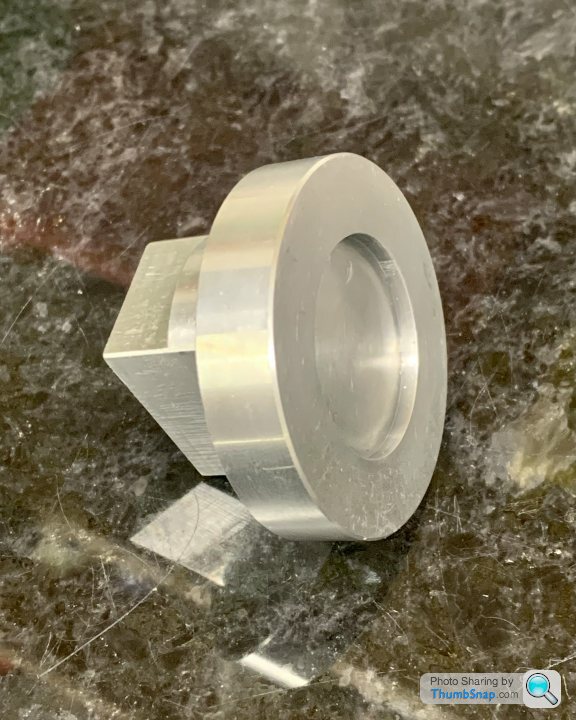
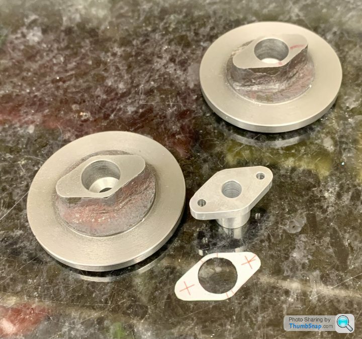
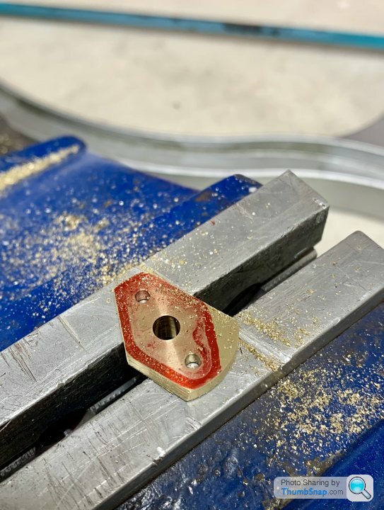
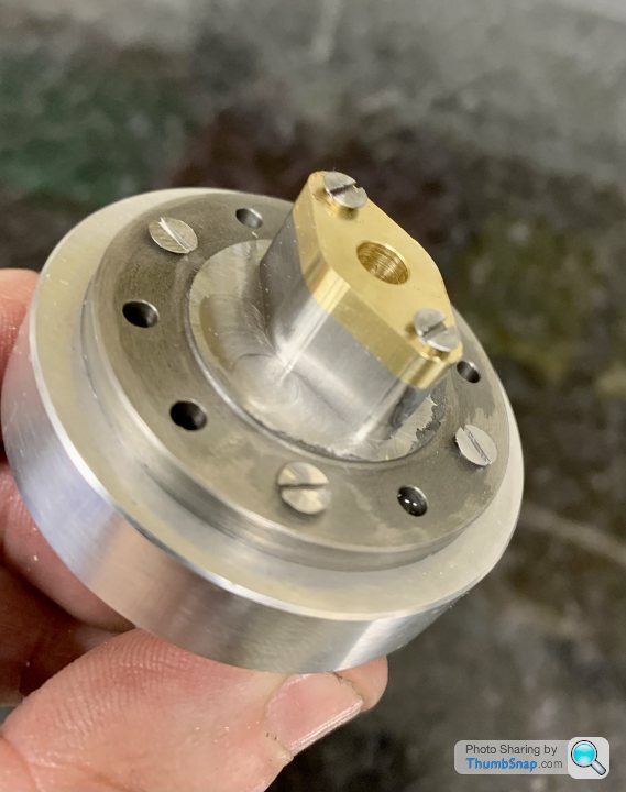
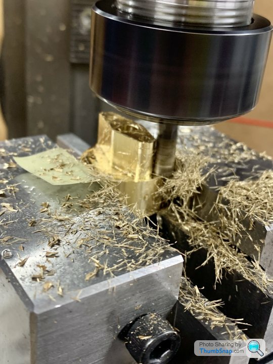
I turned some brass discs with spigots, to form the diamond shaped packing gland bosses:

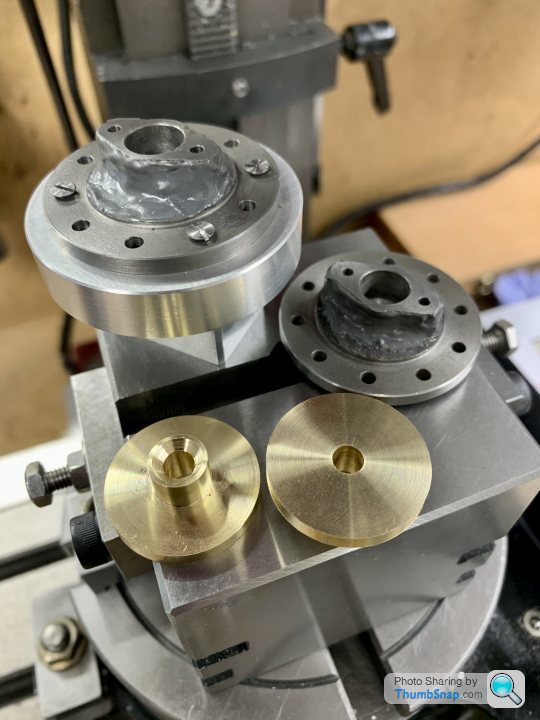
Unfortunately I drilled the piston rod holes 0.1mm too big, but the advice is to just get some 5mm ground bar for the rods, rather than 3/16”, and ream the holes to suit. So that should be fine.
Then screwed them to the caps, and roughly marked them out using the aluminium test piece as a template:

Then roughly hacksawed them to shape:
Then, after much calculation of angles and offsets, setting up, and double checking, made a start on milling the profiles:
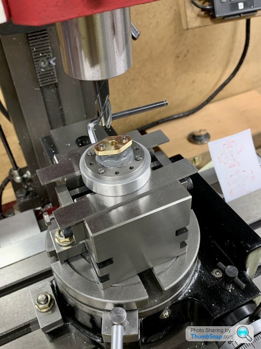
Initially used a 10mm end mill, but it didn’t seem to like it, so I switched to a 6mm version, which cut very nicely:
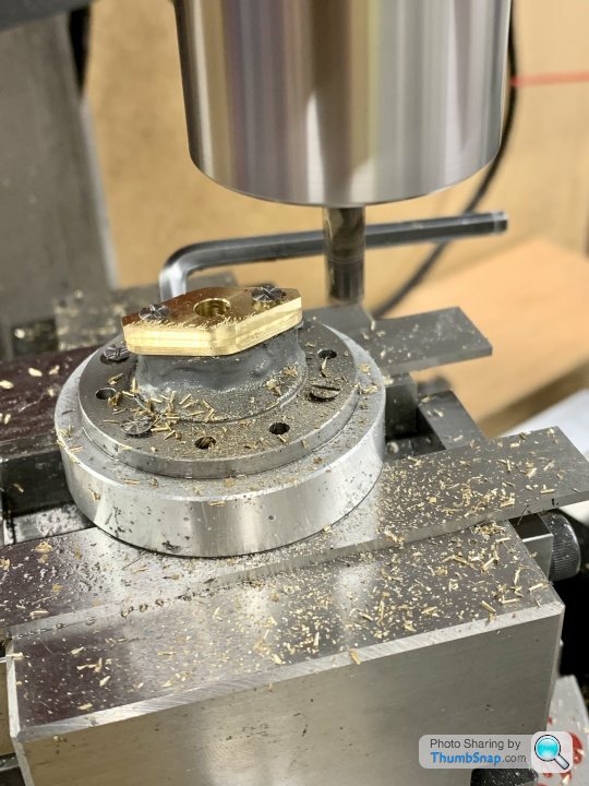
Once the sides were done, slid the fixture to each end stop in turn, and milled the end radii:
I crept up on the correct cut depths, finishing with a 0.01mm final pass both in depth and side:
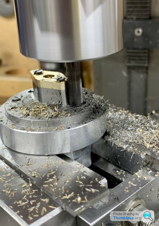
I’m glad I took a lot of care with these, because they’re right on the ragged edge of having enough metal to remove. In fact in some areas the JB Weld remains:

Despite the look, it’s smooth, and will be painted anyway.
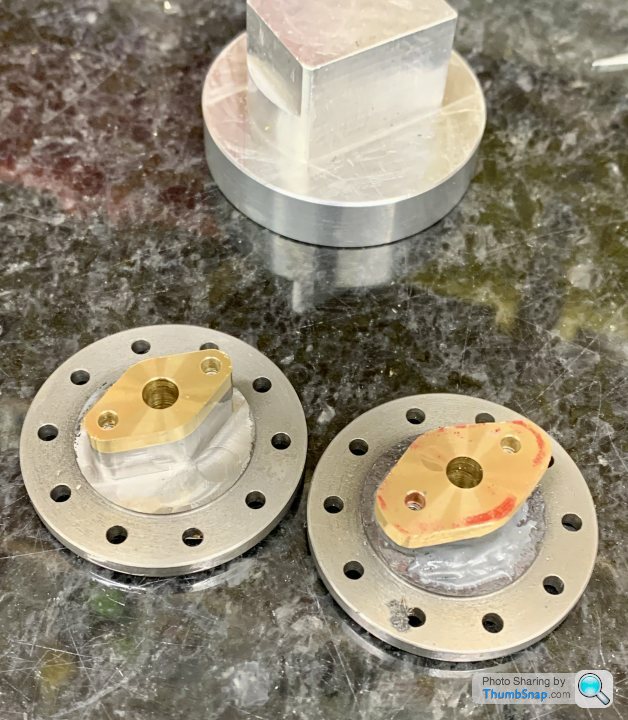
So that’s the first cover done. Still needs a quick de-burr, and a few passes with a file to get rid of any swirls in the pad (they look worse than they feel), plus perhaps a Milliput fillet radius round the boss:
Next one tomorrow hopefully:
Unfortunately I drilled the piston rod holes 0.1mm too big, but the advice is to just get some 5mm ground bar for the rods, rather than 3/16”, and ream the holes to suit. So that should be fine.
Then screwed them to the caps, and roughly marked them out using the aluminium test piece as a template:
Then roughly hacksawed them to shape:
Then, after much calculation of angles and offsets, setting up, and double checking, made a start on milling the profiles:
Initially used a 10mm end mill, but it didn’t seem to like it, so I switched to a 6mm version, which cut very nicely:
Once the sides were done, slid the fixture to each end stop in turn, and milled the end radii:
I crept up on the correct cut depths, finishing with a 0.01mm final pass both in depth and side:
I’m glad I took a lot of care with these, because they’re right on the ragged edge of having enough metal to remove. In fact in some areas the JB Weld remains:
Despite the look, it’s smooth, and will be painted anyway.
So that’s the first cover done. Still needs a quick de-burr, and a few passes with a file to get rid of any swirls in the pad (they look worse than they feel), plus perhaps a Milliput fillet radius round the boss:
Next one tomorrow hopefully:
Started to reinstate the cylinder/cap fillet radii using Epoxy filler (Milliput), and ball sculpting tools. Quite a satisfying job:

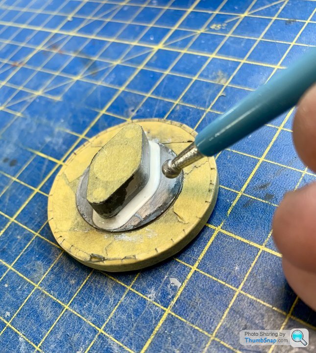
Must admit I thought this type of thing would be frowned upon among model engineers, but it seems a fairly routine technique over on the Model Engineering forums, especially when fabricating simulated castings from aluminium stock (again something I didn’t think would be so commonplace).

Must admit I thought this type of thing would be frowned upon among model engineers, but it seems a fairly routine technique over on the Model Engineering forums, especially when fabricating simulated castings from aluminium stock (again something I didn’t think would be so commonplace).
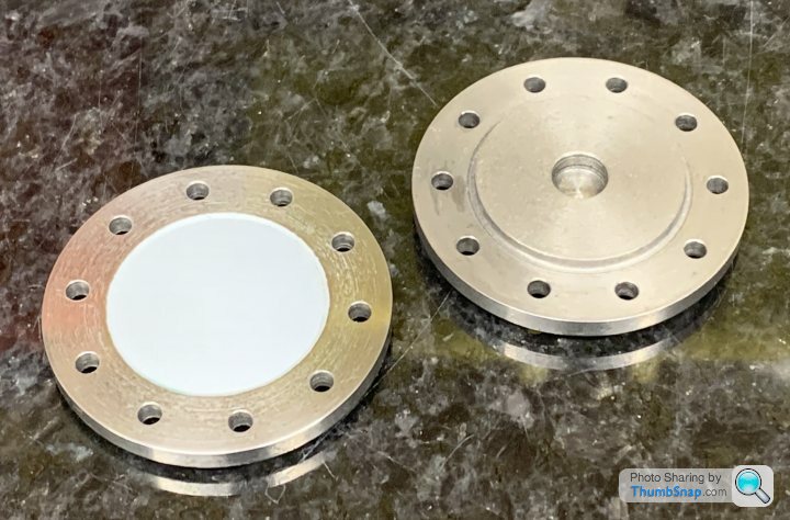
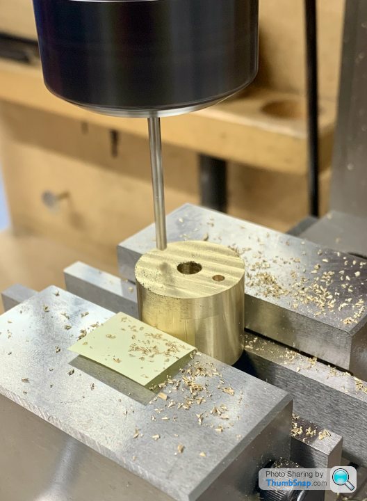
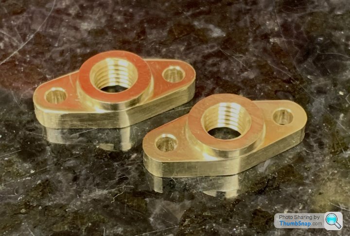
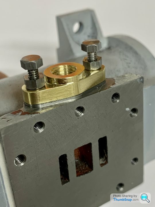
Continued with the cylinder furniture by making the exhaust pipe flanges. Again, the oval extrusions supplied were too small and a different profile to the mating pads, so I machined them from solid brass bar using the r/t:
Drilling holes first for datums:
Machining the flanks:
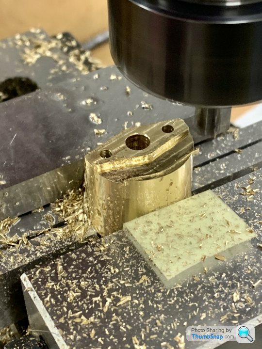
Machining the ends:
Tapping the bore:
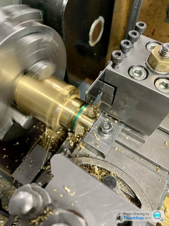
Made a threaded mandrel, and screwed up to the chuck jaw ends for turning the boss and facing to size:

Finished:
Next is to machine the oversized profile of the pads to match them.
Drilling holes first for datums:
Machining the flanks:
Machining the ends:
Tapping the bore:
Made a threaded mandrel, and screwed up to the chuck jaw ends for turning the boss and facing to size:
Finished:
Next is to machine the oversized profile of the pads to match them.
Set the cylinders up in the r/t to profile the exhaust flange pads. I thought I’d do this while the offsets and angles were fresh in my mind. First set centrally, and checked for flatness:
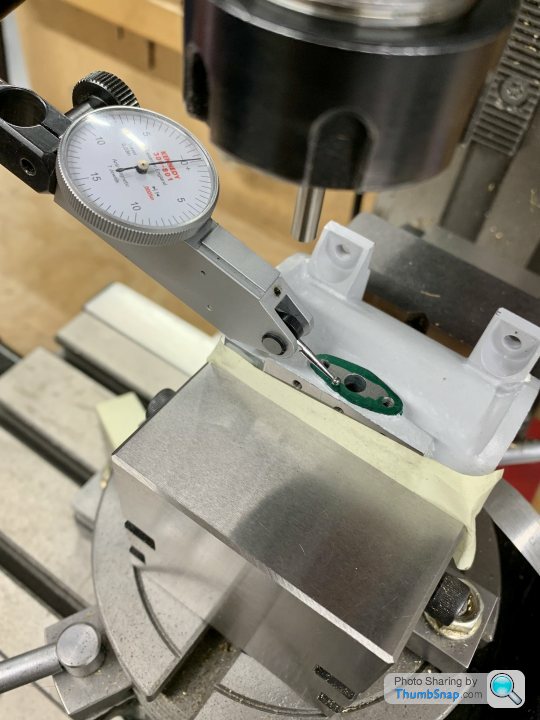
Then machined the flanks:

Then re-set with the ends central, and machined them:
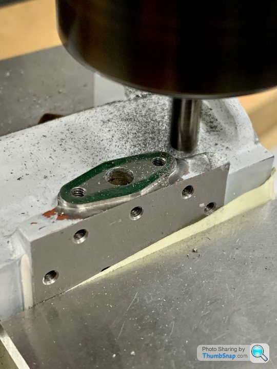
Now they’re equal:
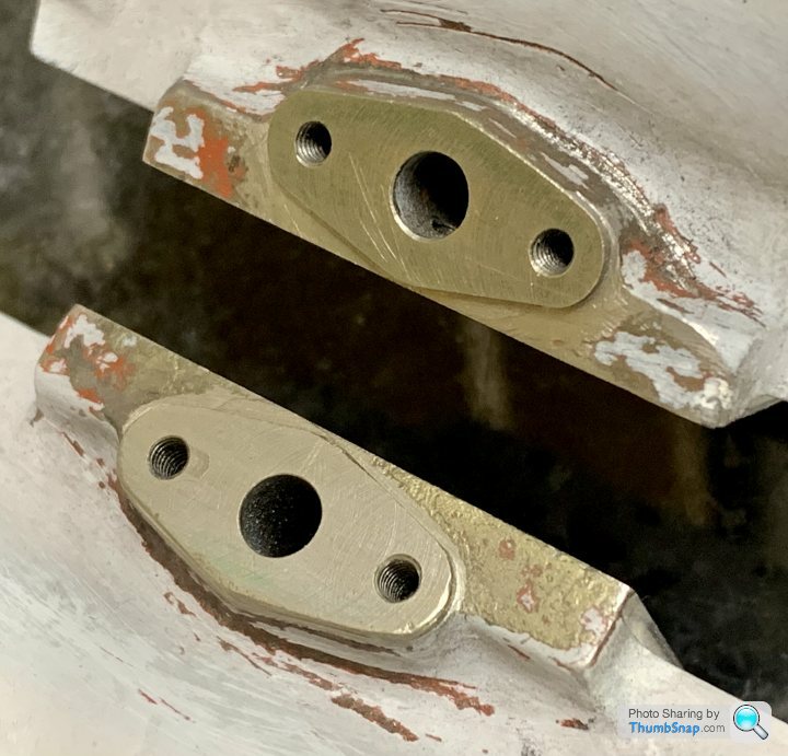
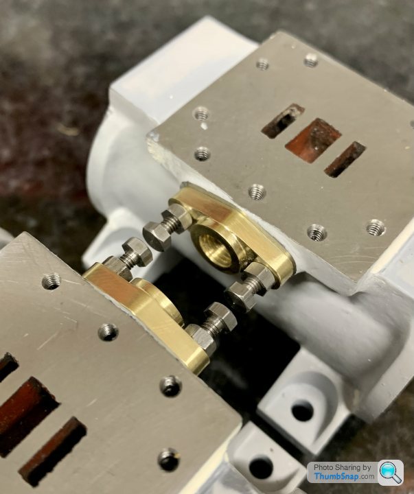
And a perfect match to the flanges:

I opted for 90 degree corners so I can recreate the radii with Milliput, and blend any slight height mis-matches into the body of the castings.
Then machined the flanks:
Then re-set with the ends central, and machined them:
Now they’re equal:
And a perfect match to the flanges:
I opted for 90 degree corners so I can recreate the radii with Milliput, and blend any slight height mis-matches into the body of the castings.

Started on the valve chest covers this evening.
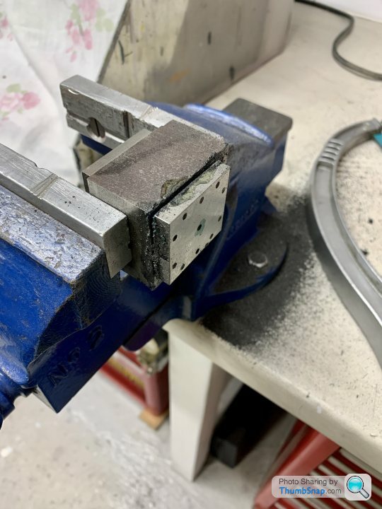
This is the cast iron block I’d got for them:
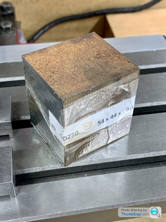
The plan was:
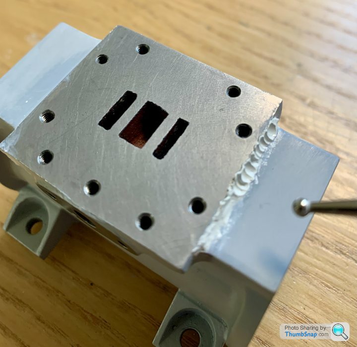
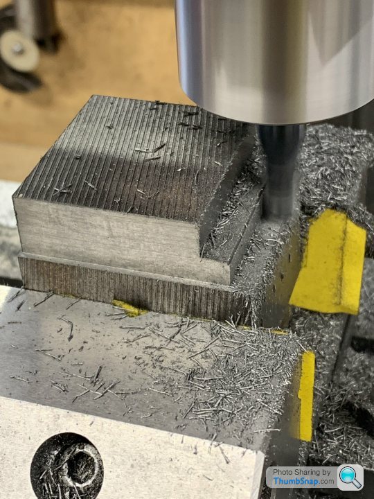
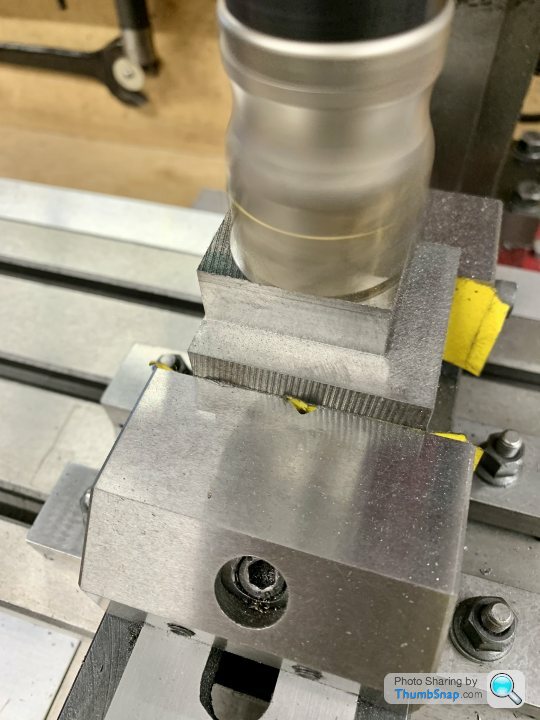
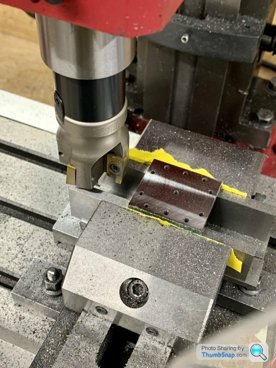
Surface the top of the block. I tried lots of methods, but the best turned out to be the shell mill:
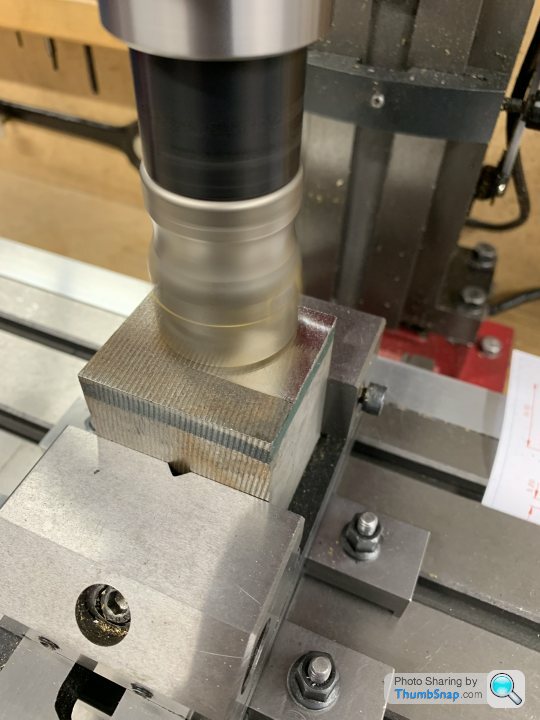
Then profile the sides to size. This is where things started to go wrong. My mill doesn’t like milling anything but aluminium. It’s horrible on steel and iron. This was the result with my 10mm and 12mm end mills:
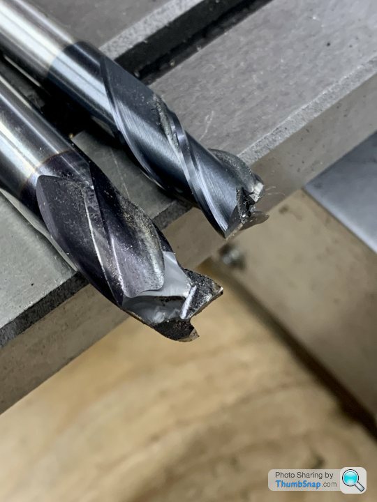
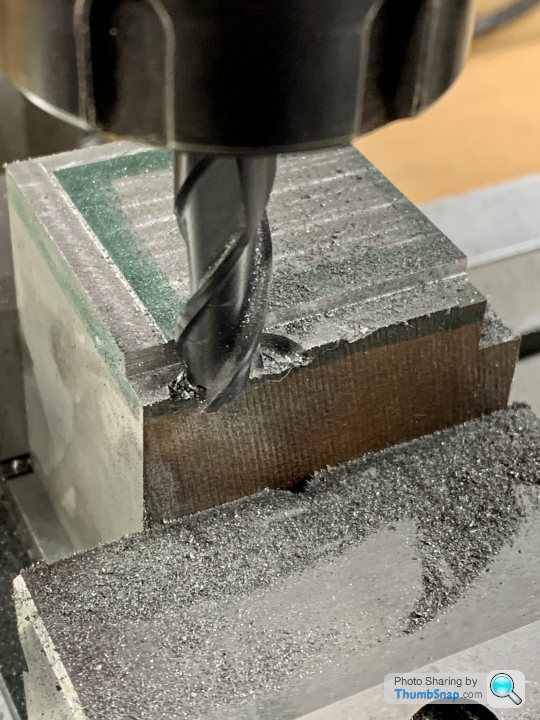
Unless the cuts are small tenths of a mm, it squeals like a pig, judders, and is generally unpleasant to use - especially side milling. Anyway, nothing new there.
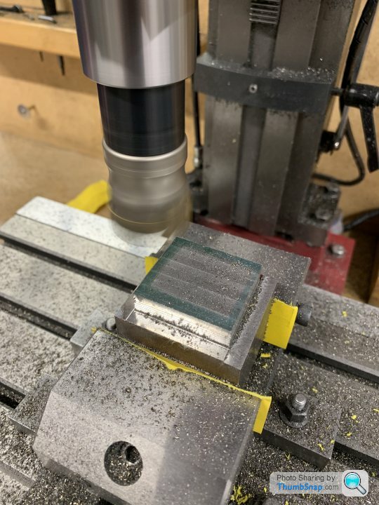
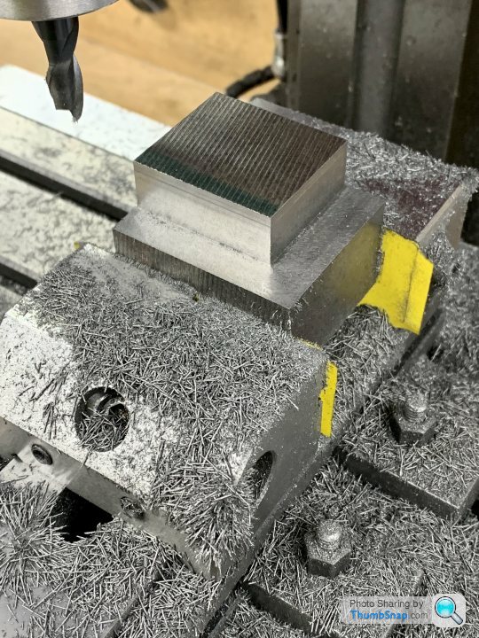
So tried again using the shell mill to chomp away at the sides and remove the damage:
Then swapped to my dwindling supply of end mills to refine the sides and get the final dimensions (shell
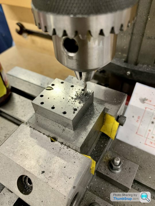
Mill doesn’t give straight sides). Trouble is, by that time it was undersized, so effectively all the work was for nothing. I decided to use it as a trial for the milled recess in the top surface:
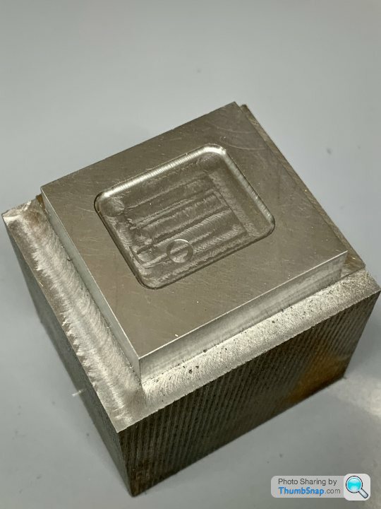
A few lessons learned there, but the 6mm, 1mm corner radius cutter worked well enough at a 1mm depth of cut.
So I’ll put this evening down to experience.
Plan now is:
1: Turn the block upside down and re-surface.
2. Profile all sides to within 1mm with the shell mill.
3. Profile to final size with an end mill (using minimal cuts).
4. Mill the recess in the top.
5. Co-ordinate drill the holes.
6. Hacksaw it off the main block.
7. Put back in vice and shell mill to thickness.
8. Repeat using the remaining profiled block.
This is the cast iron block I’d got for them:
The plan was:
Surface the top of the block. I tried lots of methods, but the best turned out to be the shell mill:
Then profile the sides to size. This is where things started to go wrong. My mill doesn’t like milling anything but aluminium. It’s horrible on steel and iron. This was the result with my 10mm and 12mm end mills:
Unless the cuts are small tenths of a mm, it squeals like a pig, judders, and is generally unpleasant to use - especially side milling. Anyway, nothing new there.
So tried again using the shell mill to chomp away at the sides and remove the damage:
Then swapped to my dwindling supply of end mills to refine the sides and get the final dimensions (shell
Mill doesn’t give straight sides). Trouble is, by that time it was undersized, so effectively all the work was for nothing. I decided to use it as a trial for the milled recess in the top surface:
A few lessons learned there, but the 6mm, 1mm corner radius cutter worked well enough at a 1mm depth of cut.
So I’ll put this evening down to experience.
Plan now is:
1: Turn the block upside down and re-surface.
2. Profile all sides to within 1mm with the shell mill.
3. Profile to final size with an end mill (using minimal cuts).
4. Mill the recess in the top.
5. Co-ordinate drill the holes.
6. Hacksaw it off the main block.
7. Put back in vice and shell mill to thickness.
8. Repeat using the remaining profiled block.
Edited by dr_gn on Wednesday 6th July 22:54
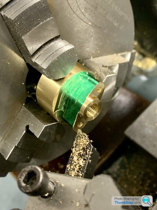
Then setup in the rotary table, centering on the oiler hole. This is what the blanks looked like:
I set up an air line to blow the chips away, I didn’t want them getting stuck in the recess:
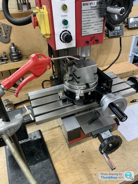
Milling the outline:
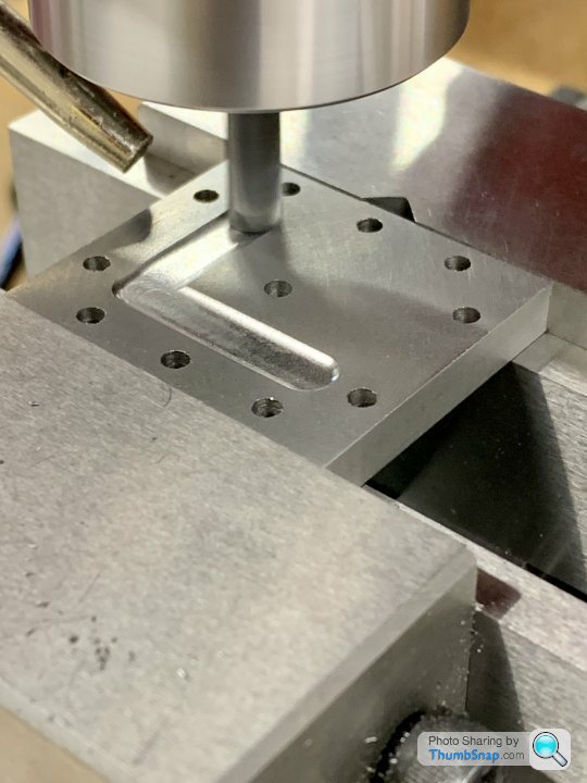
Then rotated the table around the central hole to give a radiussed pad:
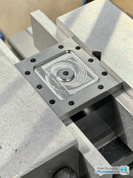
Then tapped the 5BA threads for the oilers (which I need to make):
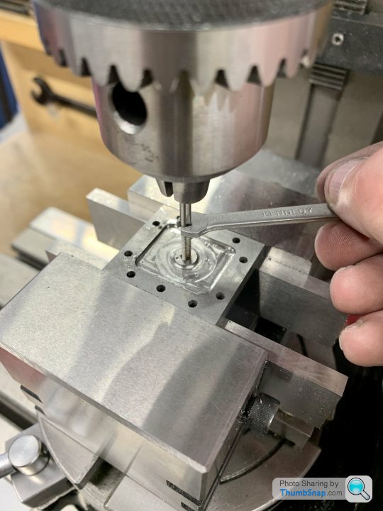
Then faced to the correct thickness:
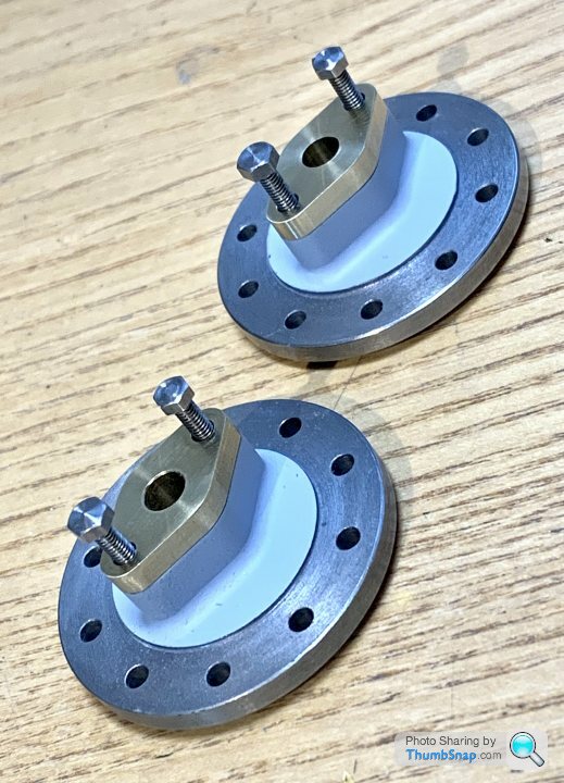
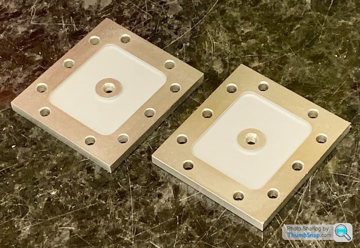
Result:

Primed:
Test fitted to the other bits:
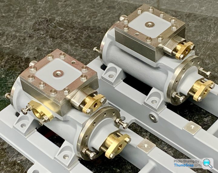
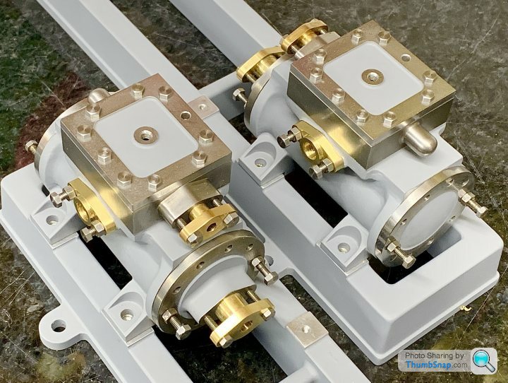
Might not look much at the moment, but there is a lot of work just in those assemblies…
I set up an air line to blow the chips away, I didn’t want them getting stuck in the recess:
Milling the outline:
Then rotated the table around the central hole to give a radiussed pad:
Then tapped the 5BA threads for the oilers (which I need to make):
Then faced to the correct thickness:
Result:
Primed:
Test fitted to the other bits:
Might not look much at the moment, but there is a lot of work just in those assemblies…
Gassing Station | Scale Models | Top of Page | What's New | My Stuff