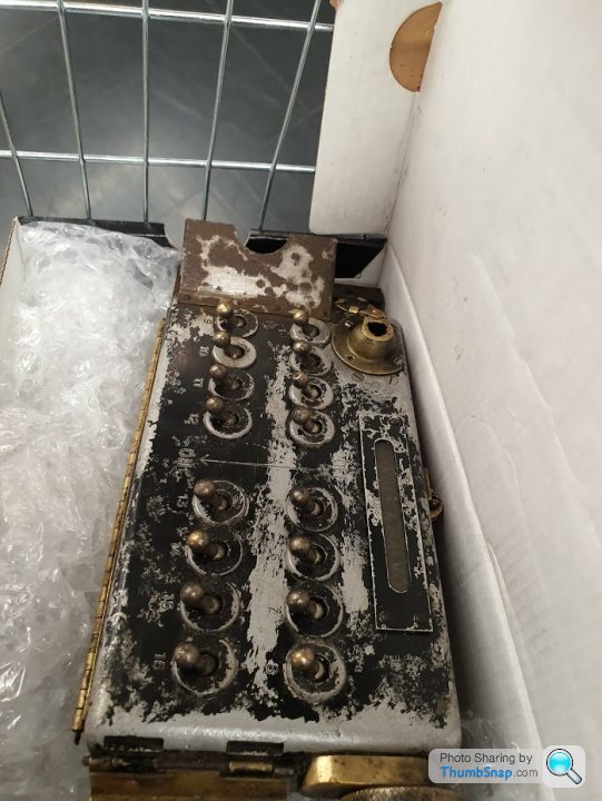
Lancaster Bomb Switch Panel
Discussion


This is based on memories from at least 35 years ago, so be gentle!
I drew a track diagram onto a bit of board, then put a pair of brass panel pins through the relevant tracks behind each set of points.
Soldered wires onto the back pins (probably actually soldered the wired on first then passed the wired through a pre-drilled hole, but you get the idea).
Wired the common of the points solenoids to -ve, the other side of the solenoids to the pins, then had a permanently live flying lead (+ve), which could be touched onto any of the pins on the track diagram to fire the points.
Simple cheap and easy.
David
Yertis said:
Dad used proper H & M point switches when he wired up my railway 40-odd years ago. It was like watching him practise magic. But couldn't you use a toggle switch to flip the polarity, then a push button to briefly energise the circuit?
Probably much easier to cough up for the proper switches...
You could, but if you flipped the switch without pressing the button (for whatever reason) you wouldn't have a positive indication of where the points were.Probably much easier to cough up for the proper switches...
dave-the-diver said:
This is based on memories from at least 35 years ago, so be gentle!
I drew a track diagram onto a bit of board, then put a pair of brass panel pins through the relevant tracks behind each set of points.
Soldered wires onto the back pins (probably actually soldered the wired on first then passed the wired through a pre-drilled hole, but you get the idea).
Wired the common of the points solenoids to -ve, the other side of the solenoids to the pins, then had a permanently live flying lead (+ve), which could be touched onto any of the pins on the track diagram to fire the points.
Simple cheap and easy.
David
Peco do the parts to make a system like that, but again, there is no idication of how the points are set, which is what I'm after.I drew a track diagram onto a bit of board, then put a pair of brass panel pins through the relevant tracks behind each set of points.
Soldered wires onto the back pins (probably actually soldered the wired on first then passed the wired through a pre-drilled hole, but you get the idea).
Wired the common of the points solenoids to -ve, the other side of the solenoids to the pins, then had a permanently live flying lead (+ve), which could be touched onto any of the pins on the track diagram to fire the points.
Simple cheap and easy.
David
Thanks for the ideas though.
Hi, I am currently a Restoration Volunteer with the National Airforce Museum of Canada. We are currently restoring a Hudson Bomber. As you can imagine, the Bomber we are working on was missing a lot of parts. One of the parts that was missing is the bomb aimer switch panel which is identical the the one used in the lancaster. I am fabricating one from scratch but photos of the sides of this panel are impossible to find. Would it be possible for you to photograph the sides? I thank you in advance for any help that you could provide.
Bob
If there is anyone out there that has one of these panels, please contact us, thanks
Bob
If there is anyone out there that has one of these panels, please contact us, thanks
Eric Mc said:
Which switch is for the Cookie?
I know this is an old post, but looking through the lanc A.P I have here, the Cookie would be armed with switch number 12 (or possibly 8, 10 and 12 as they had 3 fuses). Interesting that there are 16 switches though, as a Lancaster has 15 bomb positions (5 rows of 3).

Edited by lufbramatt on Monday 26th January 16:52


https://photos.app.goo.gl/nam5xbRMpBjwmaPR7
And a quick clip of the very satisfying thunks it makes.
(Apologies for the sideways video etc)
And a quick clip of the very satisfying thunks it makes.
(Apologies for the sideways video etc)

Just as an FYI.... if you are going to be using those, be aware the internal wiring could be asbestos. It looks like the pure chrysotile cloth wiring, and is the right age. I can't tell 100% from the photos, but you can get it tested. If it is, just be careful as it is pure asbestos.
Very cool though!
Very cool though!
It's an interesting piece of historical equipment.
Clearly it's worth some money so don't knacker it.
If you can use the switches/mechanism for yout train outfit or whatever while keeping the unit intact then fill your boots.
Some probing around with a multimeter should enable you to identify circuits and map out a schematic.
Might even be one online somewhere.. Haynes Lancaster Repair Manual?
peterperkins said:
It's an interesting piece of historical equipment.
Clearly it's worth some money so don't knacker it.
If you can use the switches/mechanism for yout train outfit or whatever while keeping the unit intact then fill your boots.
Some probing around with a multimeter should enable you to identify circuits and map out a schematic.
Might even be one online somewhere.. Haynes Lancaster Repair Manual?
Check the date on the OP. Clearly it's worth some money so don't knacker it.
If you can use the switches/mechanism for yout train outfit or whatever while keeping the unit intact then fill your boots.
Some probing around with a multimeter should enable you to identify circuits and map out a schematic.
Might even be one online somewhere.. Haynes Lancaster Repair Manual?

Gassing Station | Boats, Planes & Trains | Top of Page | What's New | My Stuff