Tapered Ring Compressors
Discussion


 it opens up a few questions, but at least it gives us some idea.
honestbob said:
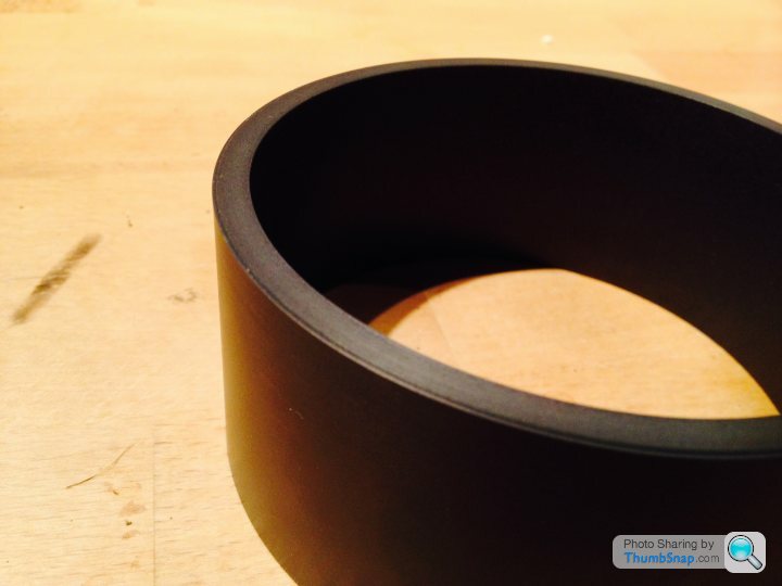
Please will someone who actually knows what is required post a simple cross sectional sketch of the component
showing clearly where this elusive chamfer is. All I can see from the photos is what appears to be a 1/32"
x 45deg. chamfer on the outside edge of the smaller tapered end of the sleeve.
No where's my 'not sure if serious' pic gone? showing clearly where this elusive chamfer is. All I can see from the photos is what appears to be a 1/32"
x 45deg. chamfer on the outside edge of the smaller tapered end of the sleeve.
 A pic was hard enough, I doubt you'll get a technical drawing!
oakdale said:
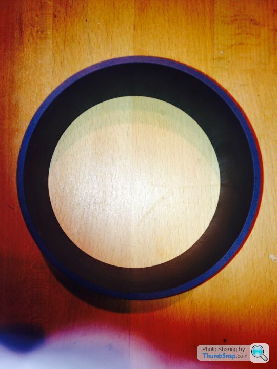
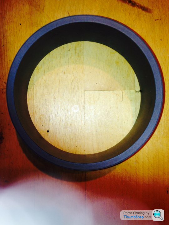
I must admit, like 226bhp I've been a little confused by some of the terms used to describe these.
Looking at the pictures it's just a metal sleeve with an internal taper, is that correct?
My mistake was thinking there had to be something to centralise it onto the bore, given the tight clearance of the bore to the the piston I couldn't see how this was so, particularly after seeing this:Looking at the pictures it's just a metal sleeve with an internal taper, is that correct?
https://www.pegasusautoracing.com/bigpicture.asp?R...
There must be different types, the end chamfer (visible in the pic) must ensure the inner part of the tool sits tight to the deck and maybe also provide some vague kind of centring.
Edited by 226bhp on Thursday 12th June 11:06
I'm still waiting for my block to be delivered, but I'm also curious as to how this is going to align with the bores. The lip machined into the face of the compressor could mate but it will depend on how the liner is set in the block... otherwise I'll need to line it up with some laser eyeballs.
Saying that it should be no more difficult to line up than standard. Remember Dave was talking about a compressor he machines.
Saying that it should be no more difficult to line up than standard. Remember Dave was talking about a compressor he machines.
m4tti said:
I'm still waiting for my block to be delivered, but I'm also curious as to how this is going to align with the bores. The lip machined into the face of the compressor could mate but it will depend on how the liner is set in the block... otherwise I'll need to line it up with some laser eyeballs.
Saying that it should be no more difficult to line up than standard. Remember Dave was talking about a compressor he machines.
If you think about it a normal compressor (sheet metal coil type) doesn't have any centring either, it just relies on the piston being a good fit - which it should be of course.Saying that it should be no more difficult to line up than standard. Remember Dave was talking about a compressor he machines.
Remember, pistons are tapered, they are wider at the bottom and more or less brush the bores, but lesser in diameter at the top.
Normally the skirt of the piston will protrude a little from the bottom of the compressor and this will provide most of the location to the bore that you need. All you need to do is to place the piston in the compressor and lean gently on it until a couple of mms of skirt protrude and then place the compressor/ piston into the top of the bore.
With the compressors I have made there is a protruding lip on the bottom of the compressor in the inverse shape of a chamfer, this fits neatly into the chamfer on the top of the bore and locks the device into place and provides a smooth uninterrupted passage for the rings.
Dave
With the compressors I have made there is a protruding lip on the bottom of the compressor in the inverse shape of a chamfer, this fits neatly into the chamfer on the top of the bore and locks the device into place and provides a smooth uninterrupted passage for the rings.
Dave
And the finished product:
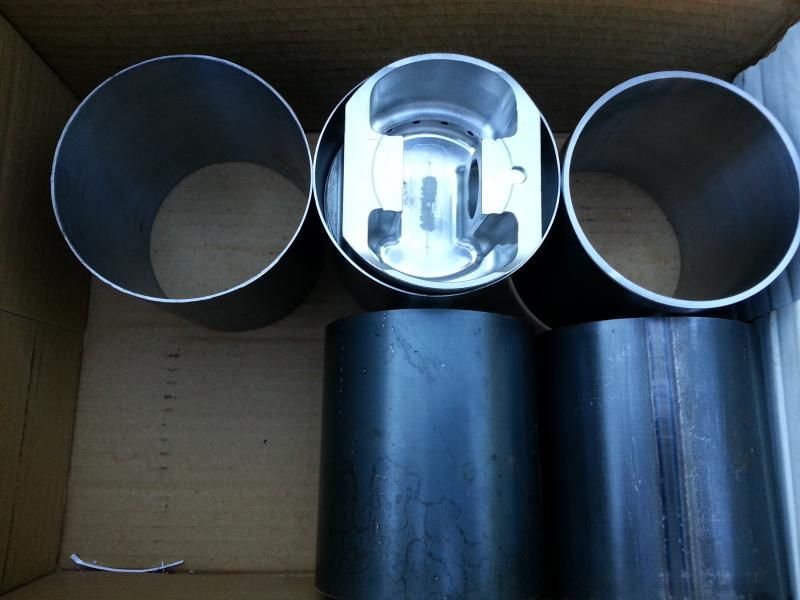
They don't look much, but didn't cost much either! I offered to make them for a mate and was going to do them myself on the lathe, but got busy with other things so took them to some local CNC turning guys I know.
Basically they are just made from some thickwall pipe. Most of the expense in machining is the set up time, so for simplicity I just got them to bore them all tapered the same from one point to another. Then I just mounted them in my lathe and parted them off to length - different length, different bore size, so a full set for one engine. They work great, very smooth and easy compared to the steel band type.
Thanks for the help and pics.
Edited by 226bhp on Thursday 24th July 08:26
Gassing Station | Home Mechanics | Top of Page | What's New | My Stuff