911 (964) Turbo - Blaupunkt CD wiring
Discussion
Hi All,
I hope I have posted this in the correct section and hope someone can help - I think this is going to be a real challenge.
Car is a 964 Turbo which has a factory fitted Blaupunkt head unit with CD Changer. The CD Changer is model no CDC-1 with Part Number 964.645.111.00.
The cable which attaches the headunit to the (power supply) of the CDC changer has come adrift. Unfortunately the 8 wires have detached from the (DIN?) connector which (obviously) has 8 pins and will now require resoldering.
I believe I have identified what the 8 wires are:
Red - 14v constant
Yellow - 14v switched
Black - Gnd
Green - Audio L
Blue - Audio R
Green / Blue - Audio Gnd
Orange - Bus 1
White - Bus 2
However, I have no idea how to match these to the correct (numbered) 8 pins on the connector.
Is anyone able to assist, or point me in the right direction?
Many thanks in advance, if any further information is required I will do my best to provide it.
Thanks both.
Porsche want to charge me £420 for a new cable (it is a Porsche, maybe also VW specific part, so not available at Halfords etc)
The link was very interesting and came close to solving the issue, I just need the colour to pin number relationship for a 8 pin DIN?
Any other ideas, thanks for reading, I realise this is a very specific issue!
RC, thanks again. I have trawled Google images but without joy.
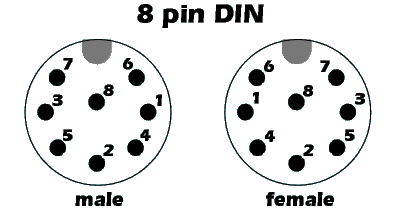
The plug itself is not propriety, but I think the cable is. It is a standard DIN 8 pin layout like this:

I have 8 wires (which I believe) are defined as such (from a table on a wiring diagram which MAY relate to this unit):
1 = bus 1 (txd)
2 = bus 2 (rxd)
3 = 14v dauer (German for constant)
4 = 14v schalt (German for switched)
5 = gnd
6 = gnd audio
7 = audio l
8 = audio r
However linking the colours of the wires to function and then confirming that the numbers above match the layout of the DIN plug is not easy.
The only clue I have is I think the audio gnd was actually linked to pin 2 on the DIN (not pin 6 as suggested above).
Thanks again for reading and helping!
The plug itself is not propriety, but I think the cable is. It is a standard DIN 8 pin layout like this:

I have 8 wires (which I believe) are defined as such (from a table on a wiring diagram which MAY relate to this unit):
1 = bus 1 (txd)
2 = bus 2 (rxd)
3 = 14v dauer (German for constant)
4 = 14v schalt (German for switched)
5 = gnd
6 = gnd audio
7 = audio l
8 = audio r
However linking the colours of the wires to function and then confirming that the numbers above match the layout of the DIN plug is not easy.
The only clue I have is I think the audio gnd was actually linked to pin 2 on the DIN (not pin 6 as suggested above).
Thanks again for reading and helping!
Gassing Station | Porsche Classics | Top of Page | What's New | My Stuff


