The Kit Car Design Thread
Discussion


Hi all,
I came on here to idly look at some posts on a completely different topic (a clue, think of some people arguing a lot), but came across this thread as well. Typing as someone who is a very frustrated stylist/designer - and there is a big difference - I would love to make a contribution on here; it just means I need to get the crayons out then.....
Personally I think there are one or two particular vehicles that are crying out to be transformed into something either contemporary or retro, and I hope to make some form of a valid contribution in the coming weeks. Just how good they are compared to some of the great efforts already posted remain to be seen though lol
The only thing I can say on my side is that I styled up a Bentley coupe when I was a teenager and about three years later an identical concept car appeared at the motorshow. I think it was coincidence personally!
Everyone should have a go at this, to me this is a brilliant challenge.
>> Edited by XJS lover on Sunday 12th June 02:43
lanciachris said:
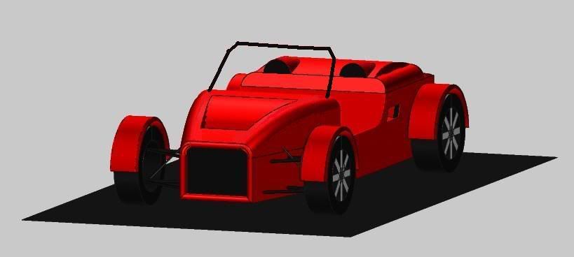
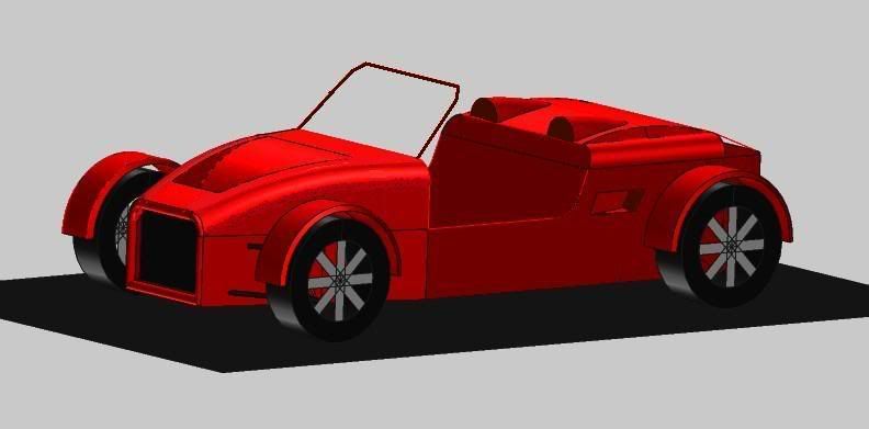
After many hours of quiet contemplation, precision measurements and technical planning, heres my effort. I think we can all agree that it is the best, and ready for production 

if that were to fit around a Corse chassis. . .

till then, i'm here


>> Edited by vojx on Monday 13th June 11:23
Vojx
Nice rendering and design, it does have potential, I would just simplify a little the front end of the concept, and use ready and available production lights.
Cymtricks
Your concept of a mid-engine seven is very forward thinking concept, and know that someone in Australia has worked on a similar design, building a running prototype.
I must have seen it on the Locost builders site, but forgot the name of it............will get back with the info on this car
Italo
fuoriserie said:
Vojx
Nice rendering and design, it does have potential, I would just simplify a little the front end of the concept, and use ready and available production lights.
Italo
the lights you see are Pug 206GTi with plastic bag coverings to protect them from wayward resin
front end needs sorting - but i've no idea what to do with it
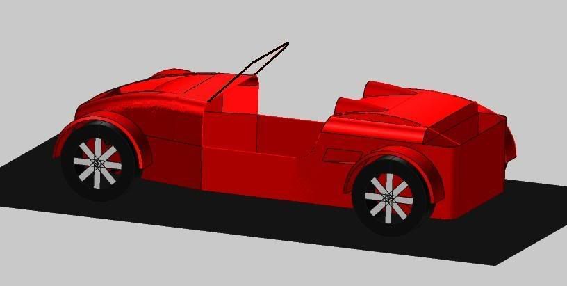
i've combined the 2 side views i've posted so far in this thread - and got something that i think is almost perfect (for me). look out for it in 2008.

>> Edited by vojx on Wednesday 22 June 11:21
>> Edited by vojx on Monday 27th June 11:33
vojx
Eliminate the first triangle in front end design, the one that has the fog lights in the drawing, and resembles the Alfa Romeo shield.
The 206 lights are a very good chioce for your design.
I will be checking with you in 2008..........and best of luck with this design project.
Cheers
Italo
Eliminate the first triangle in front end design, the one that has the fog lights in the drawing, and resembles the Alfa Romeo shield.
The 206 lights are a very good chioce for your design.
I will be checking with you in 2008..........and best of luck with this design project.
Cheers
Italo


Having noticed that the the seven replica and locost chassis is becoming the industry preferred kit, I've decided to work with them and see how many different body styles can be made using this chassis.
I need a mid-engine locost chassis for my next design....
I've seen a few of the guys are working on this idea, and hope to see the first mid-engine locost chassis soon!
The idea is of having a readily available locost seven and mid-engine manufactured chassis, that any interested manufacture would buy and then fit their own body.
You would have a cheaper manufacturing system for the new bulder, and by the same token have different body shapes.
This is the platform of the big OEM, idea transported to the kit industry( locost seven and mid-engine locost) where to bolt your new shape.
Just a thought, but design wise it makes sense for any new manufacture trying to get in the kit industry, to use this idea.
Cheers
Italo
To fuoriserie
That sounds like a good idea about the locost type chassis for general use.
I see two minor problems:
1. The Locost chassis is woefully flexible. Apparently a few changes to the back end will more than double the stiffness of the design.
2. Rollover protection would be needed for people wanting to design a closed car Vs an open one like the Locost and this may have to be looked into.
Other than that, it sounds like a very good idea - hope it works for you.
This post is sort of maybe nearly almost along the thread. I am a car modeller of many years standing; usually in metal and always large scale. I want to build a model of the Raffo Belva - as sweet a car as any I have ever seen.
Normally I would work with pen and paper to draw the plans....but I thought, Oh, well, lets see what extra functions that computing gives me regarding drafting.
After much searching, I downloaded InstaCad, a free 2D and 3D drafting program and it looks good. It's abilities at drafting certainly exceed my ability to interpret it's help file at the moment so I guess I need a lot of practice with it. Why persist with it? Well, its free and I am broke and will be until the drought breaks (worst in a 100 years they say).
I have a small problem - I cant work out whether or not Instacad is able to loft. Has anyone out there had any experience with Instacad. There is no sense for me to continue with Instacad if it cant loft.
Thanx
webrat said:
This post is sort of maybe nearly almost along the thread. I am a car modeller of many years standing; usually in metal and always large scale. I want to build a model of the Raffo Belva - as sweet a car as any I have ever seen.
Normally I would work with pen and paper to draw the plans....but I thought, Oh, well, lets see what extra functions that computing gives me regarding drafting.
After much searching, I downloaded InstaCad, a free 2D and 3D drafting program and it looks good. It's abilities at drafting certainly exceed my ability to interpret it's help file at the moment so I guess I need a lot of practice with it. Why persist with it? Well, its free and I am broke and will be until the drought breaks (worst in a 100 years they say).
I have a small problem - I cant work out whether or not Instacad is able to loft. Has anyone out there had any experience with Instacad. There is no sense for me to continue with Instacad if it cant loft.
Thanx
Hi Webrat. i have no experience of Instacad but plenty of 2D and 3D experience with AutoCAD and some others.
What do you mean by 'loft'? I haven't come accross that term before.
Regards,
Iain
The way I understand Lofting is when you go from flat 2d plans and elevations to a cross section to give the cross sectional shape of the object . I think the best way to explain a cross section is - imagine a replica 427 Cobra freshly washed, cleaned and polished and standing there on the roadway minding its own business and glistening, nay, positively sparkling, in the sun.
Now imagine some civic minded citizen comes along and slices said Cobra at right angles to the centre line, say, just in front of the dashboard, with one trememdous backhand blow.
Now, while that is an extremely sensible thing to do to a replica Cobra (and my congratulations to that civic minded citizen for maintaining the peace and honour of the realm); imagine if, to the cheers of assembled hundreds of thousands, said civic minded citizen gives said fake snake another 20 or so premeditated whacks in a positive, unflustered, controlled and genial manner. Talk about reality TV, hey!
Ok - thats what I am looking for as the first step - getting the cross sections.
If you have ever made any model aircraft then each bulkhead in the fuselage or rib in the wing is a cross section. Each bulkhead in a yatch is a cross section.
Lofting is used in boat building to describe each bulkhead. In the old days, you would quite often receive lofting details when you bought a plan for a boat. You "lofted" these details onto the wood to give a shape, cut the shape out and built the bulkheads. When all the bulkheads were all joined together according to the plan and the outside skin attached to the bulkheads to keep the wet stuff on the outside, the boat (strangely enough) was the right shape
So, the cross section gives the shape of the whatever - aeroplane, boat, car. Now, how to describe that slice so Blind Freddie or Wilful Johnny can reproduce it accurately? The second step is deriving the actual lofting values to describe that slice accurately using a grid.
For example, say you are using a grid of 50 units horizontally (25 units LEFT of the centre line, 25 units RIGHT of the centre line) and 30 units vertically, then L,10 (horizontally),2 (vertically) accurately describes a point on the slice taken at right angles to centreline and just in front of the dashboard, if I remember correctly.
If you have enough (L, number, number)s and (R, number, number)s and an agreed convention understood by all users then you can draw the cross section accurately. The convention in this case is "first number is horizontal, L is LEFT of the centre line, R is RIGHT, second number is vertical from the top line" (and no jokes from the ex-military regarding coming across etc).
Deriving those L numbers and R numbers for simply one cross section is a pain in the backside. Having to do 10 or 20 of them is not to my taste so thats why I would like to find a CAD program that can do it for me.
Incidently, the civic minded citizen mentioned in passing above was last sighted leading a sea of cheering millions towards the small yet justly famous village of Much Binding in the Marsh where (it has been rumoured) 17 Cobra replicas were to be excommunicated, defenestrated, hung, drawn and then burnt at the imitation snake; I beg your pardon, that should read, fake stake.
Gassing Station | Kit Cars | Top of Page | What's New | My Stuff