540HP NA 7L V12 3 seater
Discussion


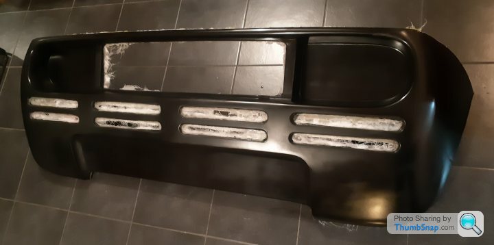
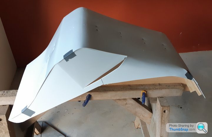
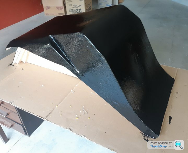
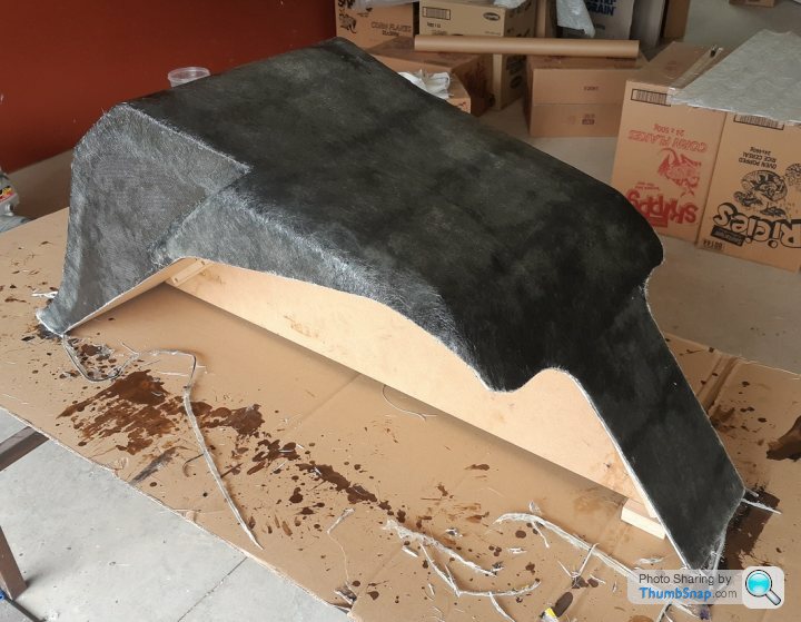
Milestone reached - rear panels pop off the tooling relatively easily when the proper PVA film is used. Very glad to have the goal (and experience) behind me and can now move on with the build.
Next milestone is the drivers seat in Carbon fibre, then the passenger seating buck mold (cabin), then the chassis proper.
Next milestone is the drivers seat in Carbon fibre, then the passenger seating buck mold (cabin), then the chassis proper.
Thanks Rob,
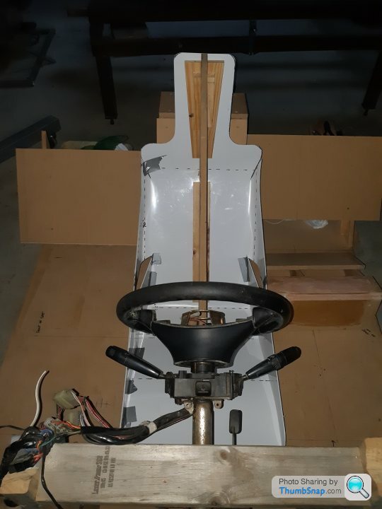
I am using the old engineering technique of "Socks, then shoes." Cabin ergonomics and comfort are critical to the end experience, hence the upcoming focus on the driver and passenger seats. Once the cabin tub exists it will be placed on the build table and the frame built to the CAD model, however if any tubing needs repositioning it can be done without compromising the human interface. The fuel tank is highly dependant on the cabin being 100% complete as it must be a very tight fit to give maximum capacity. Once the cabin is frozen in place then major systems like font and rear suspension, steering and engine/trans package follow.
I did not expect the rear panel to take as long as it did, but all the techniques learned accelerate the next stages. I built the rear panel to see if the results I could achieve were going to look acceptable and reach a kill milestone as early as possible. It is such an iconic rear end and if it it was not "right to the eye" then not much point in proceeding with the rest of the bodywork - would have had to restyle as a cybertruck.
Edited by F1natic on Monday 25th July 01:08
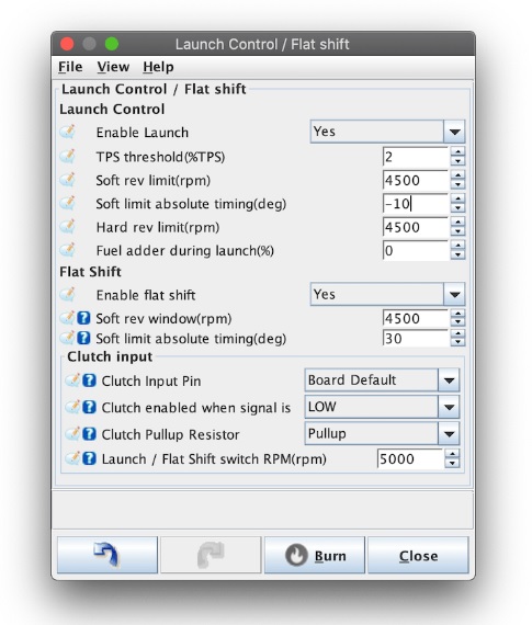
Back in April 2020 there was a discussion here about how the separate clutch bite points might cause a behaviour where the free engine could rev up under the "moving off" throttle setting, especially for a hill start. Learned the standard Speeduino launch control could be programmed in Tunerstudio to a low rpm setting to fake an "anti-stall", it only needs a clutch switch to feed a signal to the correct input pin. Will use the spare hall effect sensor to read the clutch position and an isolation switch on the control panel to turn the feature on or off on the fly - i.e. once the clutch pedal is pressed both engines will only rev to the set point regardless of throttle position, however once clutch pedal is released (or no voltage is supplied to the signal pin) normal throttle response continues. The first test drive will quickly establish if this feature is required, but will wire it into the ecu harnesses regardless.
Shown below is the wiki screen shot for the feature so would set launch rpm to something more like 2000 rpm.
Shown below is the wiki screen shot for the feature so would set launch rpm to something more like 2000 rpm.
Edited by F1natic on Sunday 14th August 08:58
The above solution is for a problem I don't actually have, any bumper to bumper city driving could easily be achieved with just one engine. Open road with twin engines will have fast shifts anyway.
The build has just had it's first anniversary...
Happy with the tire to rear panel gap.
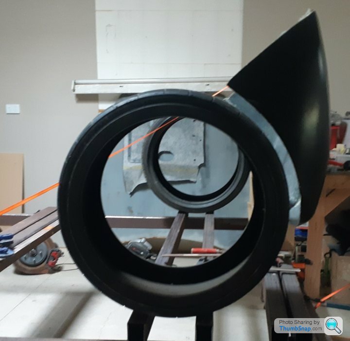
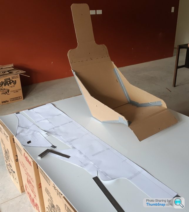
Working on the drivers seat currently, really happy with the feel of the cardboard mockup so committing to making a plug for it, however the plug will be adjustable if required. Cutting the template out from 1/8" polypropylene sheet and attaching to a wooden buck, if the seat that the tool produces is not right can easily adjust it and remake tooling. Means I can avoid the sanding malarky that the rear panel encountered = faster results!

The build has just had it's first anniversary...
Happy with the tire to rear panel gap.
Working on the drivers seat currently, really happy with the feel of the cardboard mockup so committing to making a plug for it, however the plug will be adjustable if required. Cutting the template out from 1/8" polypropylene sheet and attaching to a wooden buck, if the seat that the tool produces is not right can easily adjust it and remake tooling. Means I can avoid the sanding malarky that the rear panel encountered = faster results!
Thanks for the encouragement chaps.
With a little help from a 2kw heat gun was able to coax the polypropylene sheet to fold where needed and retain on a MDF profile template. Will put filleting wax over the screw heads to give a flush surface before applying the tooling gelcoat, fibreglass and polyester resin. Once the rough seat tooling is made from this plug a polyester/glass seat shell will be made and shaped foam blocks added do the internal cavity to give a snug comfortable fit. Plan is for a smooth CNC cut plug for the final road going version to produce an epoxy/carbon fibre tool & part for certification load testing.
The plug fits nicely into place in the seating buck.
The curved sides are important for seatback stiffness but more importantly a space for passengers arms, while the cutout at the bottom of the seat matches the inwards angle of the structural spars either side of the driver, which allows for more space for passenger hips.
Edited by F1natic on Monday 26th September 03:51
Goal here is a fast and low cost seat tool that will produce a seat shell to verify driver movement and comfort in the cabin mockup. At this stage and for early test drives an ugly fibreglass unit is sufficient.
Sealed up all the screw heads and gaps with filleting wax
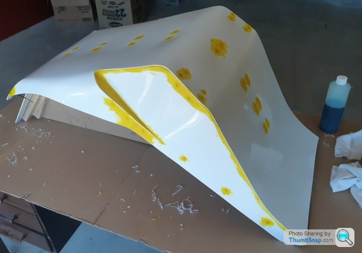
Gelcoat
Cheesey state of first stage of laminating resin is very easy to trim to the shape of the seat pattern.
Sealed up all the screw heads and gaps with filleting wax
Gelcoat
Cheesey state of first stage of laminating resin is very easy to trim to the shape of the seat pattern.
Edited by F1natic on Monday 26th September 03:48
Thanks very much for the heads up! Some great details on construction, very timely information. Not often you find genuine hens teeth for sale, let alone 2 of them. Will be fascinating to see what they go for.
https://www.ebay.co.uk/itm/255598669085
https://www.ebay.co.uk/itm/255598669085
Edited by F1natic on Friday 30th September 00:23
Sometimes a project reaches a stage where the fear of getting things wrong overpowers the confidence to progress. I have been wibbling for the last few weeks making minor changes to a cardboard & MDF mockup of the cabin to get everything goldilocked. However there comes a time when you have to commit to building the design, at which point it is merely a case of pouring in materials and labour. Other projects vie for attention and often serve as justifiable distractions.
Therefore under the "measure twice cut once" philosophy currently fitting the MDF templates over the "ideal interior" part to enable a fast and accurate plug construction phase (goal is to use minimal amounts of bog to save sanding time). The mould will be built over the plug and after cure the floor sections of the plug remove so that the mould is propped up directly. Hammer blows downwards onto plug extensions will shock the plug off the mould as given the weight of the plug gravity should assist release nicely. That's the plan anyway - more photos of stuck moulds are possible however draft is generous this time.

Therefore under the "measure twice cut once" philosophy currently fitting the MDF templates over the "ideal interior" part to enable a fast and accurate plug construction phase (goal is to use minimal amounts of bog to save sanding time). The mould will be built over the plug and after cure the floor sections of the plug remove so that the mould is propped up directly. Hammer blows downwards onto plug extensions will shock the plug off the mould as given the weight of the plug gravity should assist release nicely. That's the plan anyway - more photos of stuck moulds are possible however draft is generous this time.
Edited by F1natic on Saturday 26th November 03:12
RandomTask007 said:
Love the work so far. Lurking for a bit now as I've been planning a very similar build for years. Should be starting in about a year once my garage is done but plan on going Hartley 1GZFE w/ xtrac 1529.
Looking forward to your progress!
Edit:Forgot to ask,are you planning on selling casts or would you be interested in making an extra set? Would save me a lot of time
Thanks 007, I like your powerplant combo - will be VERY effective. I look forward to your progress too!Looking forward to your progress!
Edit:Forgot to ask,are you planning on selling casts or would you be interested in making an extra set? Would save me a lot of time
I am not sure if any of my oddball parts will be useable to anyone else given my fairly unique setup.
RT007, that would be quite the score and would really boost your project. For this project the goal is not mm precision, doubt mine will ever be parked next to a real one enough to notice any differences, however would hate to spend all this time and effort to create something that looks "off" from the get go.
When I built the rear panel I had some really rough scan data from a model, however had to match a CAD surface to the rough scan data to produce the CNC cutting paths, as the NC package I use can't cut 3D scan files directly. A bigger budget would no doubt allow a timesaving direct method, however all the industrial scanning I have had done needed "post processing" to clean up surfaces anyway, so a fudge factor creeps in. With CAD based surfaces the zebra stripes will show curvature issues. On a panel such as the nose it's fairly smooth so would get a good capture, but ideally any shiny or polished surfaces need spraying with a matt coating and alignment dots applied before scan. There is a matt spray that evaporates and leaves no trace but again $$.
10kg mass for the nose panel is my new target, thanks for the link.
Sounds Wurth a try! thanks Roy.
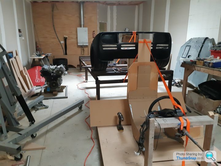
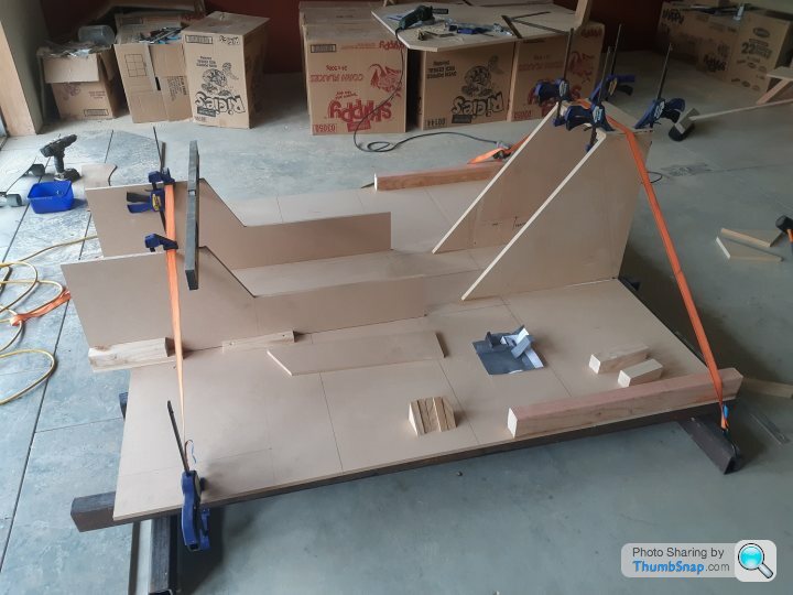
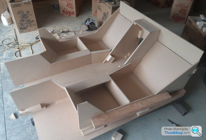
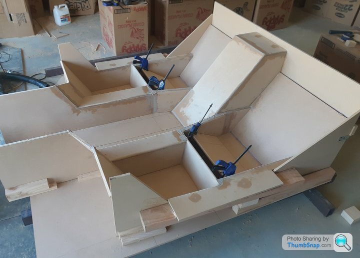
A half plane section 1:10 scale model of the interior plug can be seen sitting on the partially built fullscale example. The cornflake boxes have proven to be superb at supporting the MDF sheets while cutting out the profiles using a circular saw and jigsaw. Doesn't matter if I cut into them and they are very easy to reposition for odd shape cuts. Plus they were free and I still have lots leftover for Nerf war fortresses. Have set 2 degrees draft on these vertical faces so release should be easier - busy waiting for glue to set.
The 2 mirror image interior panels join down the entire centerline. The panels enter the interior through the door aperture and can be installed into or removed from a completed spaceframe.
Edited by F1natic on Sunday 11th December 08:36
normalbloke said:
Have you seen the thread of the chap cutting the body off the Aston for a rebody?
No I hadn't, my own project tends to make me a bit myopic. Have just lost a few hours of my life down a triple thread rabbit hole - thank you for sowing those crumbs, what an inspiring project.And here I was thinking that my upcoming reveal of the new tool at work was going to entertain some people, looks like I will have to up my ante considerably in 2023!
Edited by F1natic on Monday 26th December 21:09
Petrus1983 said:
And now a McLaren VW for our trio of nut jobs I meant clever people!
https://www.pistonheads.com/gassing/topic.asp?h=0&...
So much to admire on these projects, they make me realise I need to spend way more money!https://www.pistonheads.com/gassing/topic.asp?h=0&...
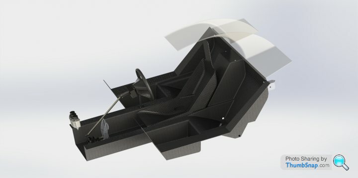
Thank you for the detailed info. Could you give a bit of detail on the tub construction, from what I have been able to decipher the layup looked like a fully flat base structure was made first, then bonded to the spars and seat bulkhead. The glasshouse roof assembly was then attached and the main chassis element then resulted. All the panels were non load bearing, other than considerable aerodynamic loading of course.
Did the tunnels formed in the spars carry the coolant lines and electrical looms? Interested in how road debris/dust/water ingress is sealed from entry to crevices in the tub structure.
Did the tunnels formed in the spars carry the coolant lines and electrical looms? Interested in how road debris/dust/water ingress is sealed from entry to crevices in the tub structure.
Edited by F1natic on Monday 26th December 21:24
Superb insight, thanks again.
Radii have been added to edges and epoxy bog fills the gaps. Once the bog cures sanding will flat off all surfaces then primer will be sprayed on. Flat sand the primer then release wax will be slowly and carefully applied in multiple coats over a few days. Filleting wax will finish off the internal corners before spraying with a good film of PVA release agent.
Radii have been added to edges and epoxy bog fills the gaps. Once the bog cures sanding will flat off all surfaces then primer will be sprayed on. Flat sand the primer then release wax will be slowly and carefully applied in multiple coats over a few days. Filleting wax will finish off the internal corners before spraying with a good film of PVA release agent.
Happy new year to all. It seems like the last 12 months went by rather faster than usual. Really going to have to focus on increasing my output in 2023 or this thing is not going to get completed.
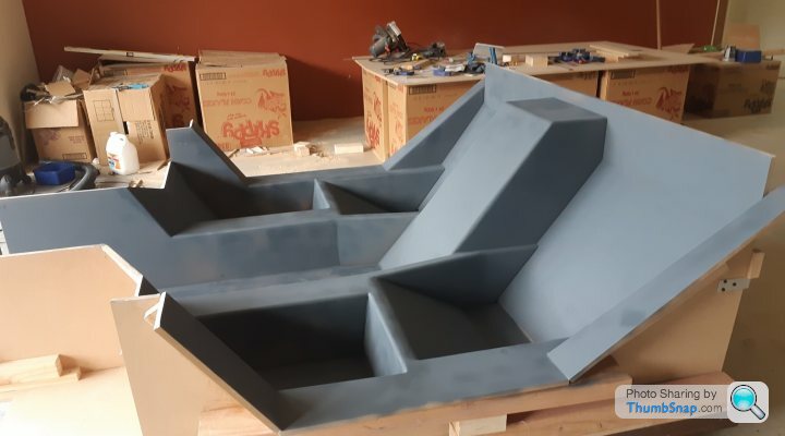
Interior plug has first patchy coat of primer on it, very proud of the overall accuracy and alignment of both sides, it is within a few mm of the latest CAD model. The passenger seats are really comfortable with a bit of padding in place, so all the fussing and delay was worth it. If this plug survives the polyester tooling being removed (and I will be doing a lot of waxing to ensure it does) then it will be kept aside for the final carbon/epoxy tooling in a few years time. Polyester/glass is fine for the test mule.
Now that the bottom of the door aperture is tooled the door design and final hinge detailing can progress - using dummy doors initially. Doors really force a decision on windscreen selection - a problem that has been put off for as long as possible as there is no good "off the shelf" option currently.
 [url]
[url]
It was interesting to reflect on the very subtle changes compared to the original CAD model from early 2021. Biggest improvements are fuel tank cover size and position and all footwells being properly sized.
Interior plug has first patchy coat of primer on it, very proud of the overall accuracy and alignment of both sides, it is within a few mm of the latest CAD model. The passenger seats are really comfortable with a bit of padding in place, so all the fussing and delay was worth it. If this plug survives the polyester tooling being removed (and I will be doing a lot of waxing to ensure it does) then it will be kept aside for the final carbon/epoxy tooling in a few years time. Polyester/glass is fine for the test mule.
Now that the bottom of the door aperture is tooled the door design and final hinge detailing can progress - using dummy doors initially. Doors really force a decision on windscreen selection - a problem that has been put off for as long as possible as there is no good "off the shelf" option currently.
[url]It was interesting to reflect on the very subtle changes compared to the original CAD model from early 2021. Biggest improvements are fuel tank cover size and position and all footwells being properly sized.
Edited by F1natic on Tuesday 3rd January 06:47
Gassing Station | Readers' Cars | Top of Page | What's New | My Stuff