540HP NA 7L V12 3 seater
Discussion


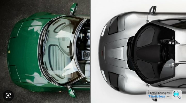
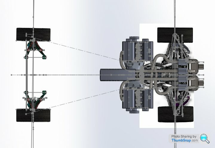
The top view shows the most obvious differences, so am fairly confident the original screen is not repurposed from existing stock.
Interesting link for some of the small parts from the M100 that were used on the F1 though - https://www.youtube.com/watch?v=_rYSWyNY9ys
Interesting link for some of the small parts from the M100 that were used on the F1 though - https://www.youtube.com/watch?v=_rYSWyNY9ys
Edited by F1natic on Thursday 5th January 21:54
I have seen youtube clips of hotrod screens being chopped with waterjet cutters, however the success rate is not 100% as far as my research shows as the stress distribution in each screen varies (polarised light shows this residual stress very clearly). LVVTA would accept scratch resistant polycarbonate if the glazing option cannot be solved practically, PC would be cheaper and quicker to fabricate option, however I need to pursue all glass options before making the screen frames and doors. The test mule will certainly use a polycarbonate screen, however goal is to have a glass unit ready to fit for certifying stage - a long way off yet.
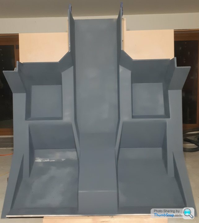
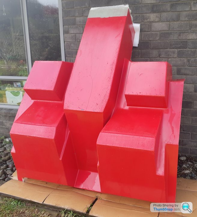
Making big molds stable in multiple orientations is definitely an advantage. Finding and repairing all the little surface defects is certainly easier once the first primer layer was applied. Second primer layer went on much easier in the vertical position, last primer layer today then sand flat with 240 grit then 400 grit.
Due to the gap caused by the removable passenger seat panel a pile of bog shavings was able to fall out when disturbed by the spraygun blast, out onto the freshly painted left passenger seat. I hate it when that happens - sanding will rectify that.
Due to the gap caused by the removable passenger seat panel a pile of bog shavings was able to fall out when disturbed by the spraygun blast, out onto the freshly painted left passenger seat. I hate it when that happens - sanding will rectify that.
While waiting for paint to dry progressed the front left upper wishbone and coilover mount, will cast this and check the result before making the RH side. Will be simple to change the caster and camber angles by unbolting this unit and replacing with one with the wishbone mounts in a different position, intention is to not have to modify the spaceframe while tuning the handling. 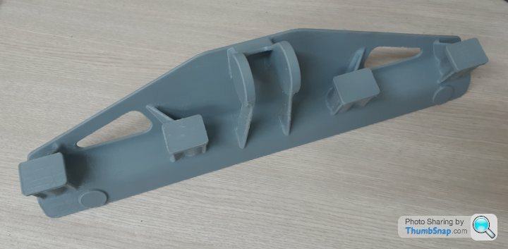
Thanks Voldo, no I don't have anything on social media, almost every update is done here. The ECU related stuff is on the Speeduino thread under the same title as nobody has published details on getting the Honda J35 engine running on that platform yet, so sharing the learnings where I find them. Really want to get both engines to synchronise for a nice V12 sound however that can only happen when the ECU is open source variety, hence the choice of Speeduino.
We don't run aluminium often as sandcasting tends to be a more cost effective method for castings. No issues raised by LVVTA about the casting I am using, but would expect it is very much on a case by case basis.
Filament is the "cast grey" that I worked with Ben at Imagin plastics to develop for lost PLA use, we get really good results from it.
Edited by F1natic on Wednesday 1st February 07:03
Will do Dom.
Waxed the plug multiple times, added fillets to all corners and sprayed all over with PVA release film.
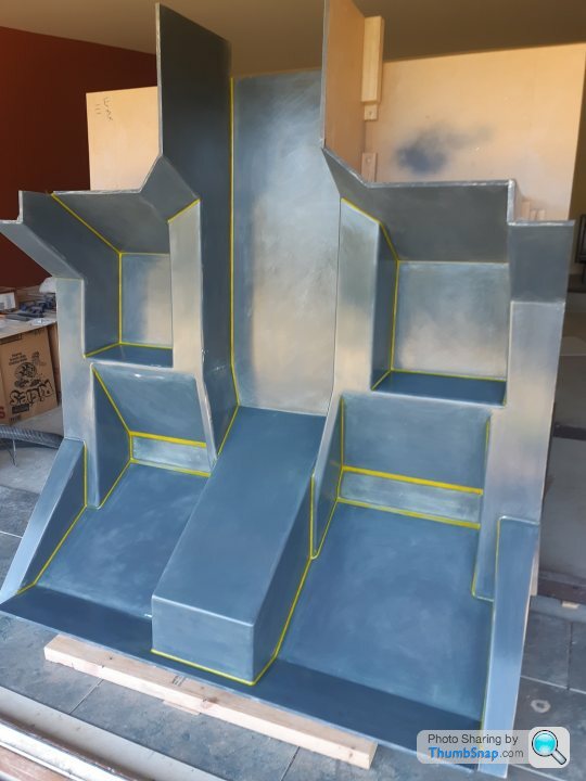
Had to work very quick to get this all spread before it gelled, one area had slump which thickened and went off quicker than desired. A small amount of sanding in the trouble spot tomorrow and another coat of gelcoat should smooth the surfaces out enough to progress to layup.

Waxed the plug multiple times, added fillets to all corners and sprayed all over with PVA release film.
Had to work very quick to get this all spread before it gelled, one area had slump which thickened and went off quicker than desired. A small amount of sanding in the trouble spot tomorrow and another coat of gelcoat should smooth the surfaces out enough to progress to layup.
Edited by F1natic on Wednesday 1st February 07:06
Tissue and a couple of layers of 200g/m2 bidirectional glass cloth have been applied to the plug but some major lessons learned on getting faster at layup. Made one big blunder and took too long with one section, resin started to get cheesy on the other side and I had to pull it off and chuck in the bin before it set on the plug. Good thing is the resin mostly went with the cloth so cleanup the next day was simple.
Have really struggled with getting tight corners to conform if the cloth is long, basically playing whack-a-mole with bridged cloth, stipple it into one corner and the tension pulls out the corner done previously. Now using 3" wide tape to reinforce the corners and cloth panels between the tape, very easy to work the cloth into position and the bubbles and kinks out. Top flange edge is a little shorter than it should have been so clamping coreflute strips on while curing to keep a nice sharp flat edge, otherwise the cloth seems to want to curl off and cannot be moved once set. A few layers of chopped strand mat to go then the big moment.
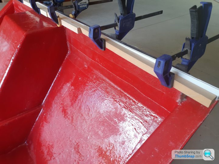
Have really struggled with getting tight corners to conform if the cloth is long, basically playing whack-a-mole with bridged cloth, stipple it into one corner and the tension pulls out the corner done previously. Now using 3" wide tape to reinforce the corners and cloth panels between the tape, very easy to work the cloth into position and the bubbles and kinks out. Top flange edge is a little shorter than it should have been so clamping coreflute strips on while curing to keep a nice sharp flat edge, otherwise the cloth seems to want to curl off and cannot be moved once set. A few layers of chopped strand mat to go then the big moment.
dom9 said:
Would be very interested in the process for the 3D print -> cast part, when the time comes... lots of pics please!
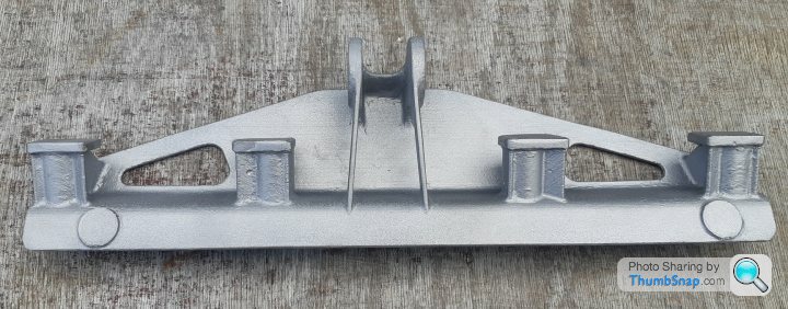
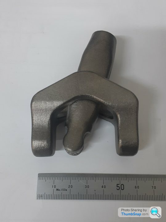
Dom, Since you asked here are the results of the first trial part. Main thing is to have a good 3D print as every surface blemish is replicated by investment casting. Essential rule is to feed the metal from thick to thin so that the part does not short fill or have internal shrinkage. Final prep of the cast metal surface is easy but time consuming and it can be faster to sand the pattern instead, however in this case I decided not to pour hours into cleaning up the pattern in case it did not succeed. I am quite chuffed with this result. Now to print the other side.
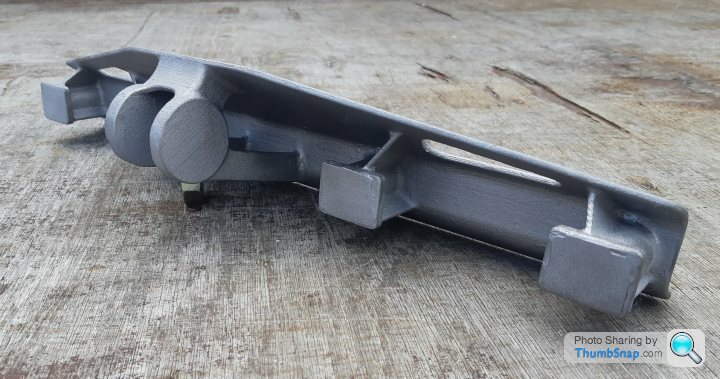
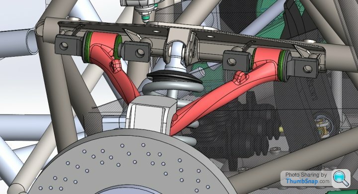
With the CAD model from last July as context;
Bulkhead mould update - removable panels came off easily and the mould is nearly finished, the 450g CSM is VERY resin thirsty and I ran out part way through. Now have enough to finish the job and bust it off the plug in a few days all going well.
Edited by F1natic on Wednesday 1st February 05:51
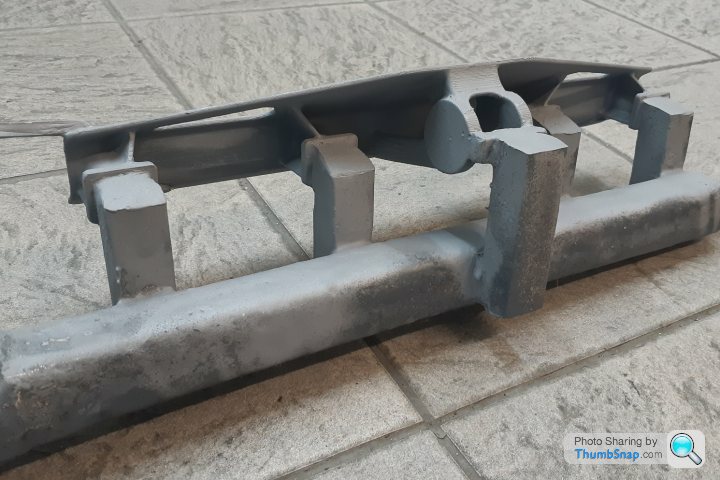
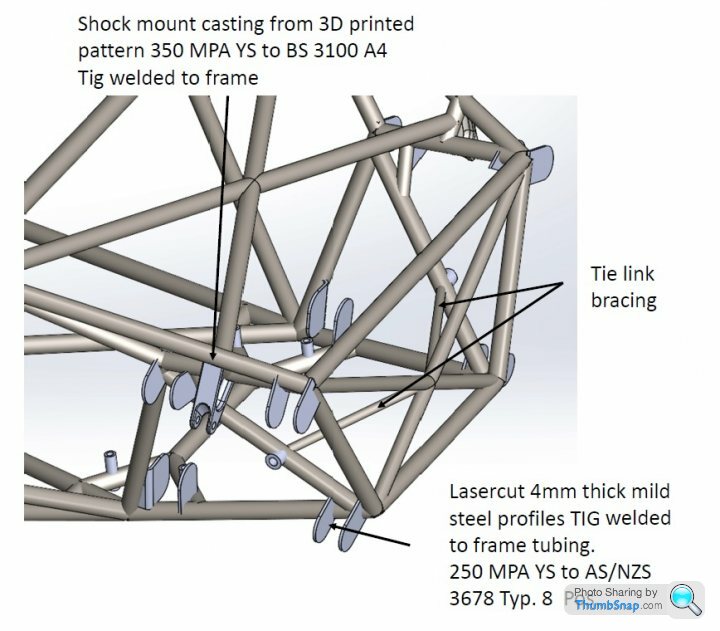
Thank you all for the input, appreciate other eyes on the design. Thanks Skwdenyer for posting the close up and notes, the casting is bolted to the chassis tubes in 4 positions (at the ends near nodes with multiple tubes and 2 at the "shock tower"). The shock loads go directly into the chassis plate and backing tube so the casting is almost continuously a "spacer" under compression. The outer dogbone towers carry the majority of the upperwishbone loads to the casting mounting bolts at either end (The 2 bosses are visible in the underside photo). The towers locate the dogbones and are on a plate that has flanges both sides so that overall flex is decreased.
Perhaps I should have stated the part was cast in carbon steel BS 3100 A4, 320Mpa minimum yield, which has good strength and ductility. For the purposes of entertainment (the whole point of this build log) and review I will explain the loads and review a couple of good examples from recent high end sports cars later, however right now my focus this Waitangi long weekend is getting the interior bulkhead mould finished and off the plug.
Perhaps I should have stated the part was cast in carbon steel BS 3100 A4, 320Mpa minimum yield, which has good strength and ductility. For the purposes of entertainment (the whole point of this build log) and review I will explain the loads and review a couple of good examples from recent high end sports cars later, however right now my focus this Waitangi long weekend is getting the interior bulkhead mould finished and off the plug.
Edited by F1natic on Friday 3rd February 20:11
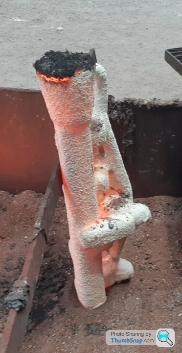
Dom, yes it's the "lost PLA" method. Same overall process as lost wax (https://www.investmentcasting.org/what-is-investment-casting.html) however the hollow PLA print is sealed and then used inplace of a wax pattern. You have to print the pattern at a slightly larger scale to cover the metal shrinkage rate for the part (which is geometry and metal dependant). The pattern is then glued to the standard wax tree using a sticky wax. Once the ceramic shell is formed it is then fired at 1000C which completely burns out the PLA if it has a low ash content. If the feeder system is good then you stand a good chance of getting a result, however it can be an iterative process. Being able to tweak the pattern at each iteration helps hone in on the best casting.

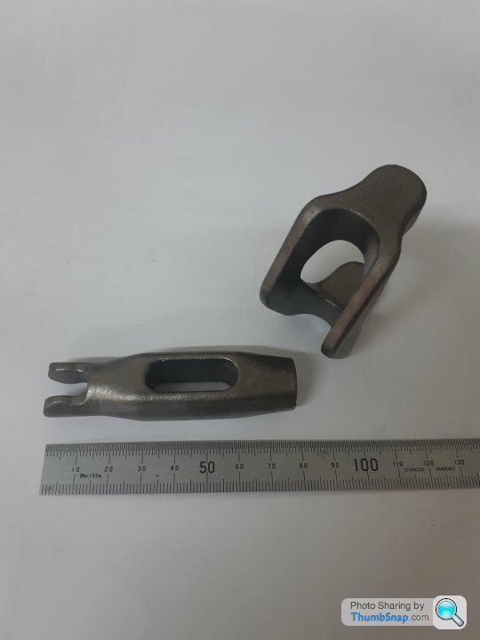
Have the full set of shock mount castings made, bit of surface clean up then off for normalising heat treatment. Some simple machining then the parts will then be ready to weld to chassis tubing.
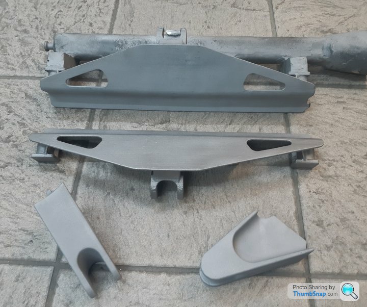
A bit of rear subframe detail showing the handed rear shock mount castings in situ. I like triangulation.
A bit of rear subframe detail showing the handed rear shock mount castings in situ. I like triangulation.
Edited by F1natic on Tuesday 7th March 06:50
Thanks for the positive encouragement, it's either going to be an epic win or an epic fail, but I am having fun building it regardless!
Windscreen search has progressed sideways - measured up a potential option from an NA2 Honda NSX as it looked like a contender with modification, however proved to be 150mm too short. Have watched just about every movie of an F1 that is near overhead lighting or a straight edge in an attempt to "ray trace" the curvature and it definitely has a compound curve at the upper edge that blends into the roof - it's quite the unique shape.
Once the interior bulkhead is mounted to the build table the gear box will be positioned temporarily and shifter operation tested. In preparation for that event have made a couple of small parts for the shift reverser (3D printed patterns cast in 316 stainless - detailed in this thread back in June 2021!!).
Thanks Paul, the Cizeta has always inspired me.
Not much visible progress on the build table, but all the shock mounts are back from heat treating and ready for machining when I get the next opportunity.
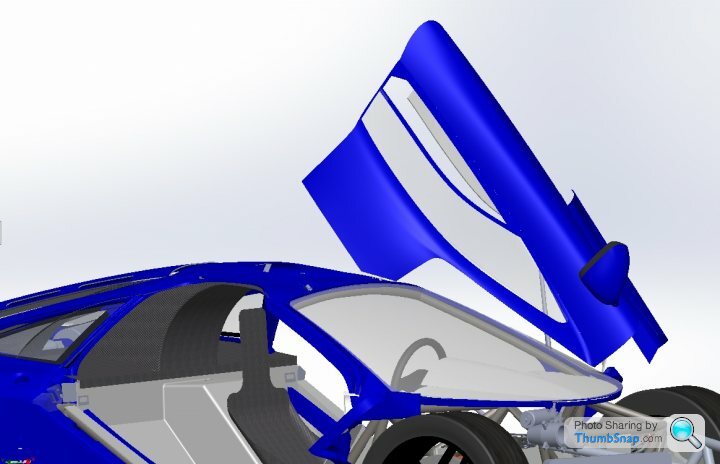
Have been adding detail to the door CAD model which had only been roughed out for the build approval stage. Tasks like ensuring the hinges and gas strut mechanisms all work as required and clear the A pillar and windscreen, as shown below. The front hinge mount and door latch incorporate lots of adjustment so that the door skin can be spaced and bolted into a position on the anti-intrusion bar that gives the best door gaps when closed. Hinges will be 3D printed and cast in steel. The hinge pin emergency release mechanism still needs fleshing out, then mocking up.
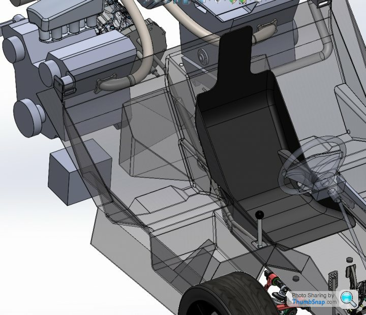
The interior plug was a little damaged during mould removal, but is now serving duty as the base for the cabin mockup. Dashboard, windscreen surround mockup, door mockups and interior roof parts will be fitted to this initially while the driveable chassis is being assembled on the build table.
Not much visible progress on the build table, but all the shock mounts are back from heat treating and ready for machining when I get the next opportunity.
Have been adding detail to the door CAD model which had only been roughed out for the build approval stage. Tasks like ensuring the hinges and gas strut mechanisms all work as required and clear the A pillar and windscreen, as shown below. The front hinge mount and door latch incorporate lots of adjustment so that the door skin can be spaced and bolted into a position on the anti-intrusion bar that gives the best door gaps when closed. Hinges will be 3D printed and cast in steel. The hinge pin emergency release mechanism still needs fleshing out, then mocking up.
The interior plug was a little damaged during mould removal, but is now serving duty as the base for the cabin mockup. Dashboard, windscreen surround mockup, door mockups and interior roof parts will be fitted to this initially while the driveable chassis is being assembled on the build table.
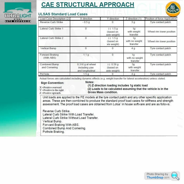
For those readers interested here is the explanation of the loading calcs for the front upper control arm bracket, using loading factors based on the ULSAS project Lotus had involvement with – i.e. an actual trustworthy internet source!
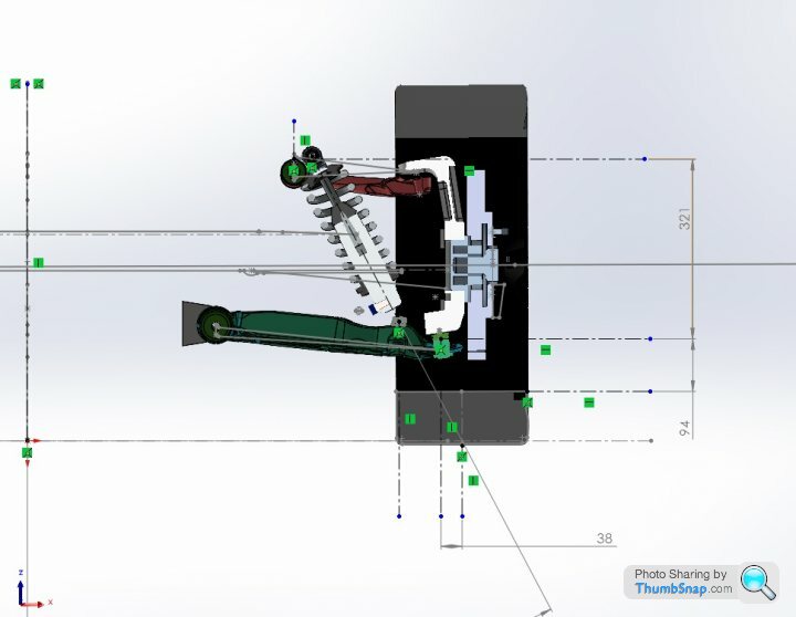
At static 1g vertical loading (assumed at the centre of the contact patch) the front corner weight in gross vehicle mass condition is 337kg or 3305N vertical. For equilibrium around the bottom ball joint the moment caused by the contact patch offset has to equal the moment caused by the upper wishbone horizontal load.
In this case the horizontal loads at 1g static are (3305N x 0.038m)/0.321m = 391N compressive or around 40kg “pushing into” the casting spread equally over the four towers.
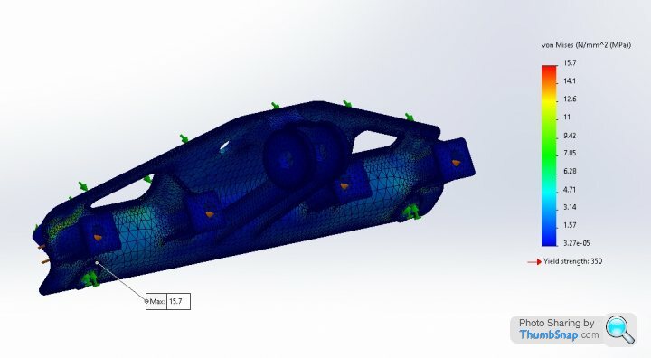
For a kerb strike the load (see table below) also includes an additional 1.5g force at the rim height which results in a tensile horizontal force of 1060N or approximately 27kg “hanging” from each of the four towers. This results in a maximum stress of about 16 MPa. Yield is 350 MPa so a large safety factor.
At static 1g vertical loading (assumed at the centre of the contact patch) the front corner weight in gross vehicle mass condition is 337kg or 3305N vertical. For equilibrium around the bottom ball joint the moment caused by the contact patch offset has to equal the moment caused by the upper wishbone horizontal load.
In this case the horizontal loads at 1g static are (3305N x 0.038m)/0.321m = 391N compressive or around 40kg “pushing into” the casting spread equally over the four towers.
For a kerb strike the load (see table below) also includes an additional 1.5g force at the rim height which results in a tensile horizontal force of 1060N or approximately 27kg “hanging” from each of the four towers. This results in a maximum stress of about 16 MPa. Yield is 350 MPa so a large safety factor.
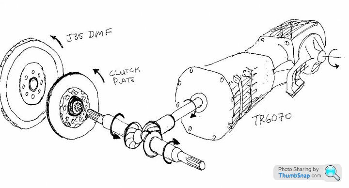
Hi Voldo, best way to describe is to refer to a few old images
There is a fairly sizeable gap between the opposing motors that the Tbox sits in. For my first pass through the design there is a very stout casting or "pumpkin", very similar to a diff head, which has large outer flanges that directly bolt to the bellhousings, which then mount and align the motors. The dual mass flywheels of the first iteration reside inside these custom bellhousings, however I have not gotten my hands on a genuine clutch assembly yet so final sizing and prototypes have not been made. I was hoping to have by now but life.
Early in the project I scoured the internet trying to find a diff that was 1:1 ratio, only thing close was a Haldex unit from a VW Golf R32, however would never have survived the torque output of the 2 V6's. I did contemplate doing a low buck grass kart of the concept using a couple of small 4 cyl engines and the VW unit, however felt it was better to build it once and prove it full scale.
The custom made pinions are subjected to quite high side and thrust forces as they are only loaded on one side, the custom made crownwheel has much less deflection due to "equal" loading on opposite sides, however it has twice the thrust to cope with. The crownwheel and pinions are all mounted in large widely spaced bearings in the pumpkin, so self-contained. The transaxle input shaft slides into an appropriately splined hole in the crownwheel, and the pinion input splines slide into the clutches. To achieve a reasonable life I was guided by the Cosworth work on the Valkyrie engine, where they designed for 250 hrs at full load. The pumpkin also has an inspection hatch so I can examine the gear set in situ during development driving, and of course the whole powerplant drops out for easy "remedial" work, which we all know will need to be done.
Did consider straight bevel gears but the life is shorter and noise too high, cabin is going to be noisy enough already.
Just found out yesterday about the Daimler Benz efforts in WW2, I think the google algorithm is getting slack.
https://oldmachinepress.com/2021/07/20/daimler-ben...
Edited by F1natic on Wednesday 26th April 09:47
Gassing Station | Readers' Cars | Top of Page | What's New | My Stuff