AWD Civic Coupe Turbo Build
Discussion


Thanks mate!
My motto is; "if it didnt cost you your marriage, you didnt do it right".. just kidding lol
I do like to do things properly, it just so happens that means it gets a little OTT.. I have to say my wife has the patience of a saint to let me do this project..
My motto is; "if it didnt cost you your marriage, you didnt do it right".. just kidding lol
I do like to do things properly, it just so happens that means it gets a little OTT.. I have to say my wife has the patience of a saint to let me do this project..
Edited by purplecivicturbo on Friday 20th January 12:34


Small update for tonight, The lower dash panels have arrived, so ive been assembling them all..
Please excuse the rough edges on the steel support structure, it still needs alot of work to fit and get it just right...
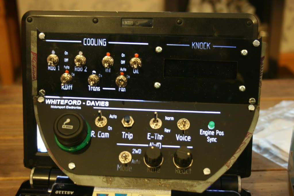
Had to use the laptop to backlight it lol.. Also the lower AWD dial text wont be lit as the pots are too big. Ill have to hunt for some compact ones..
Exactly mate..
When i built it the first time i removed the cigarette lighter and needed it for sat nav, phone, laptop on long runs .etc
It was a nightmare and i lost my rag when i was logging straight to the laptop at Oulton, didnt realise the battery was low and it just went, lost the whole session! Was gutted but it was my own fault..
I decided to put a 12v socket on it but i couldnt find a simple accessory socket at the time, so ive just used this for now, but its a standard size so i can change it at some point..
Good shout mate- im a bit thick today!
There are plenty of things like that, even gimmicky ones- cant believe i didnt realise.. lol Ill look into it!
On another note, todays update;
I put together the lighting panel for the lower dash parts, but because the LEDs ive ordered still havnt turned up, i couldnt finish it- so it went on the back burner..
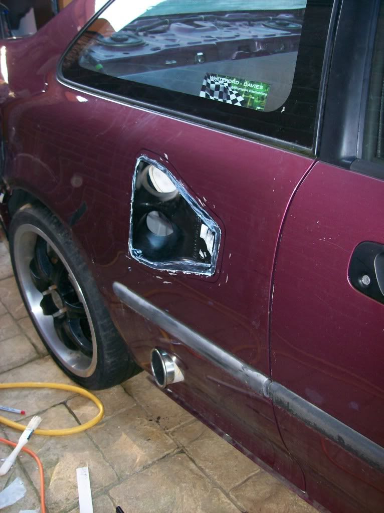
I had to do a few bits and pieces for other people too but because of my 7:30 start (i dont know either!!) i had some free time. So i decided to fit one of my side NACA inlets for the rear radiator. Excuse the "rough" appearance, its just the epoxy curing. Itll be tidied up, fillered and smoothed off..


There are plenty of things like that, even gimmicky ones- cant believe i didnt realise.. lol Ill look into it!
On another note, todays update;
I put together the lighting panel for the lower dash parts, but because the LEDs ive ordered still havnt turned up, i couldnt finish it- so it went on the back burner..
I had to do a few bits and pieces for other people too but because of my 7:30 start (i dont know either!!) i had some free time. So i decided to fit one of my side NACA inlets for the rear radiator. Excuse the "rough" appearance, its just the epoxy curing. Itll be tidied up, fillered and smoothed off..
Tah Dah!
The drive by wire computer is done!
I dont have the servo yet (expensive) to build the actuator, but the unit was tested and developed using my bench scope so it works perfectly. The unit has been calibrated to my Audi pedal and can be changed at the touch of a button. During an extensive test of 2 hours with a generic motor connected to the 6v internal PSU the system worked perfectly and the resolution stayed the same.
The computer's reaction time is as quick as you can move the pedal, there is NO lag.. Any lag seen by the system will be down to the servo, hence the cost lol
On an interesting note, the Audi throttle pedal has a built in ramp. I expected it to be a linear resistance that changes as you press it. I was going to design into the processor some profiles for faster throttle response and better drive ability ,etc. Interestingly as you press the pedal at low throttle, it requires significantly more movement. However, when you reach about 70% throttle, the response is dramatically increased.. This should lead to very good drive ability, especially over bumpy roads lol
Max_Torque said:
You can actually manage better than no lag. My electronic port throttle motor actually gets the throttle plates open before the drivers foot hits the floor ;-) (by looking at the derivative of the pedal position it can preempt a full throttle request, and because of the power of the system can get the throttle plates open in ~48ms (compared to over 100ms for the fastest the driver can move their foot........)
You sir are awesome!I hadnt even considered that.. Its quite easy to calculate the rate of change of the pedal position.. Ill probably wait till i can properly road test the changes but THAT IS HAPPENING! Thanks mate!
Thanks for that mate!
The turned pin sockets are great, i agree completely better than these ones.
However, until im happy with the design and software i need to keep taking the chip out.. Having used turned pin sockets in the past they are quite easy to bend legs on insertion.
When i have the PCBs made for the final versions, i will be using turned pins without a doubt.. I cant see being able to do away with them and soldering the chip straight in though.. Im sure ill always find something to change in the software lol
Thanks again mate!
Max Torque:
Awesome! Im assuming it worked well.. As i said, ill without a doubt look into it!
J4CKO:
Im looking forward to seeing it done too! lol.. pfft, as if a mere minion like me could have any effect on typhoon lol
MCBodge:
I think it was covered in my degree also (albeit 2010), its an interesting idea. I had never thought to implement it.. Its probably saved alot of fault finding..
Its not plug and play, at all... However, it takes feeds from normal ABS sensors.. and supplies which are available on the car anyway (such as footbrake, ignition, perminant live).
I chose it because the EP3 is fairly common on ebay and i kept my eyes out for a cheaper deal. I was originally led to believe that the internal solenoids actually biased the braking force. I checked and there is a large reduction in pressure for the rear outputs which is unfortunate.
I had mapped out the internal solenoids and worked out what they did so that i could swap it from FR-RL, FL- RR distribution so that i could tun it FF, RR with the rear supply through a bias valve.. With the internal biasiing i cant do it safely so ive scrapped that idea and ive returned it to stock..
Gassing Station | Readers' Cars | Top of Page | What's New | My Stuff