Project Thunder - Rolls Royce Meteor
Discussion


someone asked for more details on the chassis so here goes:
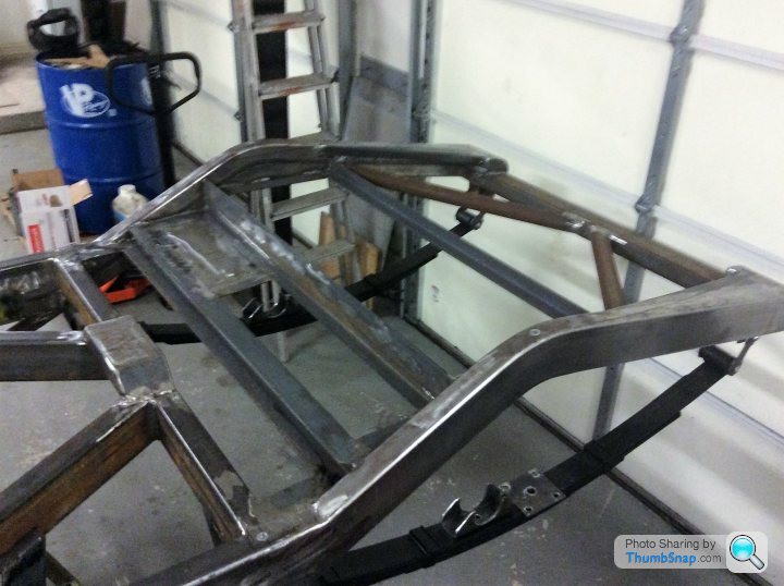
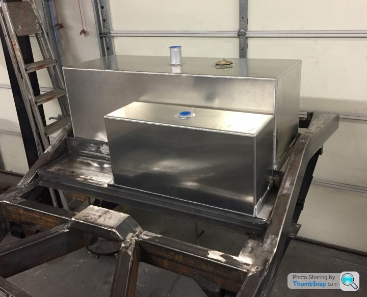
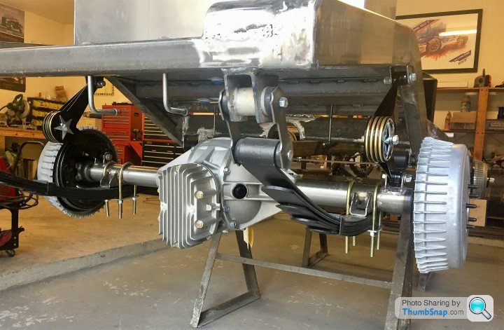
this show the cradles for the fuel and lube tanks, plus battery shelf. It also gives an idea of the rear suspension
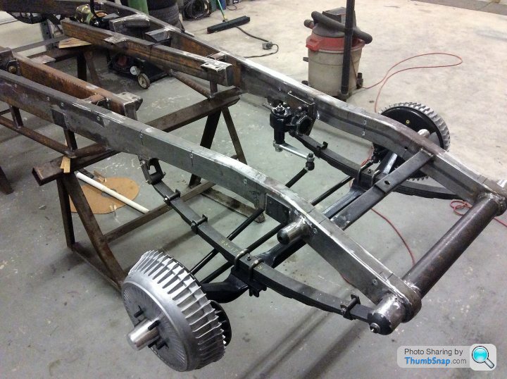
this is the front end. It uses a 1946 Ford truck beam axle with later-year Ford truck leaf springs. The steering box is from a sixties Chevy. I'll probably hsve to adjust (bend) the pittman arm once the car is on the ground in order to get it parallel with the tie-bar. The brakes look like drums but have discs inside them. The small cylinder sticking out of the frame above the axle is where the Andre Hartford friction shocks will mount
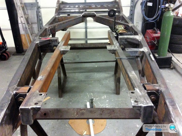
this is the engine cradle. It bolts to the frame with four 9/16/' bolts and poly bushings. The idea is to keep the engine/transmission rigid but to isolate vibrations and chassis flex.
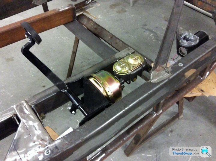
Last one is the brake master cylinder unit. It's a Corvette dual cylinder with 7" vacuum booster. I'm unsure of how much vacuum the engine will develop, so I've installed an electric vacuum pump behind the brake assembly.
Onwards and upwards!
this show the cradles for the fuel and lube tanks, plus battery shelf. It also gives an idea of the rear suspension
this is the front end. It uses a 1946 Ford truck beam axle with later-year Ford truck leaf springs. The steering box is from a sixties Chevy. I'll probably hsve to adjust (bend) the pittman arm once the car is on the ground in order to get it parallel with the tie-bar. The brakes look like drums but have discs inside them. The small cylinder sticking out of the frame above the axle is where the Andre Hartford friction shocks will mount
this is the engine cradle. It bolts to the frame with four 9/16/' bolts and poly bushings. The idea is to keep the engine/transmission rigid but to isolate vibrations and chassis flex.
Last one is the brake master cylinder unit. It's a Corvette dual cylinder with 7" vacuum booster. I'm unsure of how much vacuum the engine will develop, so I've installed an electric vacuum pump behind the brake assembly.
Onwards and upwards!
Hi Dave
Welcome.
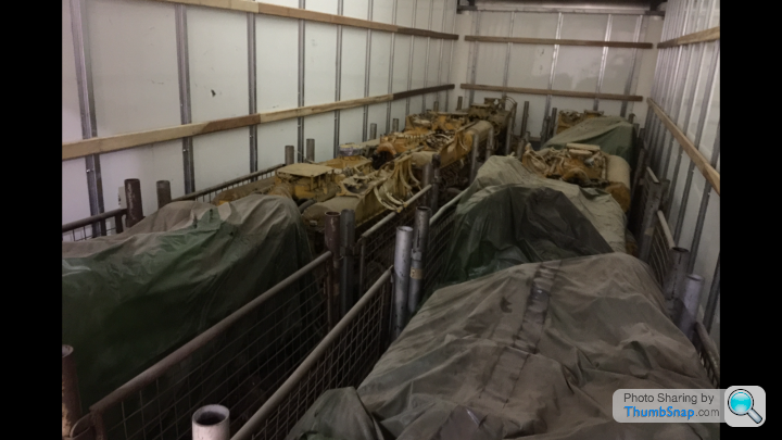
How did you acquire 14 Meteor engines in the US? AFAIK they were not used in any US equipment.
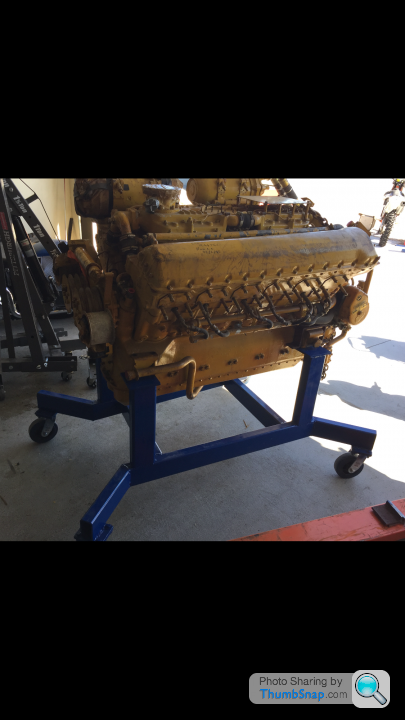
That engine stand looks familiar. Look's ones I made a few years ago.....
I built a stand to rum my Meteors.
https://www.youtube.com/watch?v=lDEBLPUHzUs&li...
That engine is a roller cam engine from the Danish army. Like hen's teeth this side of the pond, as rev's higher and less likely to cam wear. It was the first time it had run since it was refurbished.
I have others including a Mk III from WW2.
My project is on hold while I build a new business site, but I hope to get back to it by the middle of next year.
More info on your plans would be interesting.
Welcome.
How did you acquire 14 Meteor engines in the US? AFAIK they were not used in any US equipment.
That engine stand looks familiar. Look's ones I made a few years ago.....
I built a stand to rum my Meteors.
https://www.youtube.com/watch?v=lDEBLPUHzUs&li...
That engine is a roller cam engine from the Danish army. Like hen's teeth this side of the pond, as rev's higher and less likely to cam wear. It was the first time it had run since it was refurbished.
I have others including a Mk III from WW2.
My project is on hold while I build a new business site, but I hope to get back to it by the middle of next year.
More info on your plans would be interesting.
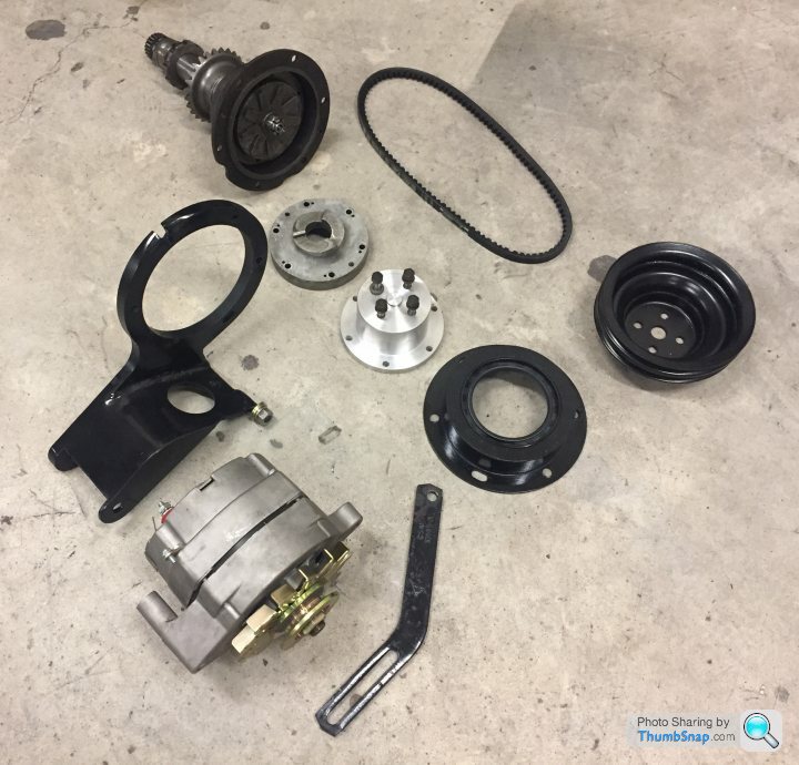
fuel and lube oil tanks installed, but more importantly, I've figured out how to safely dismantle the engine's wheelcase (it would be so nice to have a decent Manual for this engine; the only thing I have is an old WW2 document that has zero illustrations and is therefore essentially useless). Pulling the snout of the engine off has allowed me to design some adaptors to fit an alternator to the front of the engine. I'll post pix once the parts are machined, but it should be a neat set-up. Richards Bros in Cardiff seem to be making good progress on the wheels, can't wait to get them so I can put the chassis on the floor.
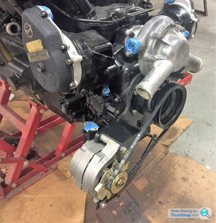
finished the mods required to fit an alternator to the nose of the engine where the giant starter used to live. I had a 1/2" plate bracket water-jetted out to fit over the existing starter motor studs. Then I machined an extension to the engine's starter dog, and finally made a lip seal cover that slides over the extension onto the starter motor studs. The pictures should be self-explanatory. After a few false starts I discovered that the bolts inside the front of the engine are actually BSF, and eventually manged to find some of the correct length to allow fitting of the extension. After that, it all went together easily, see before and after photos. I've also started cleaning and detailing the engine itself, including recoating the magentos in their original crinkly finish. Presently waiting on parts; once the C-6 arrives I'll be able to design the adaptor plate and get the unit into the chassis.
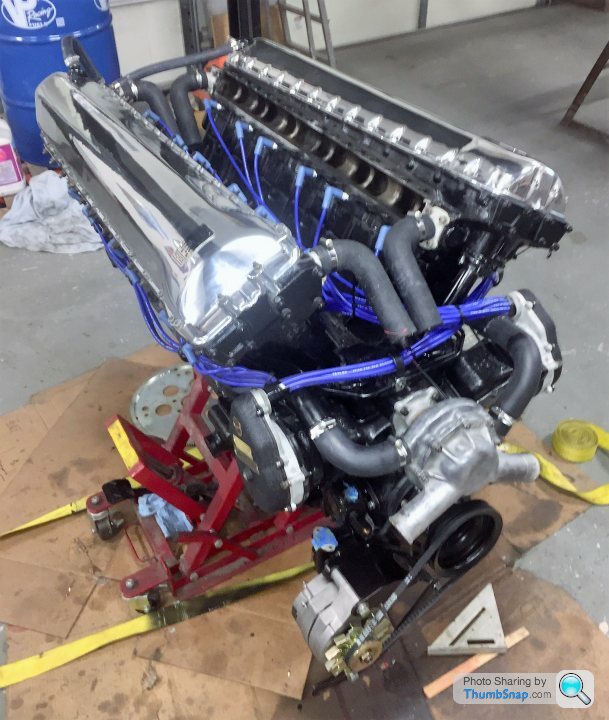
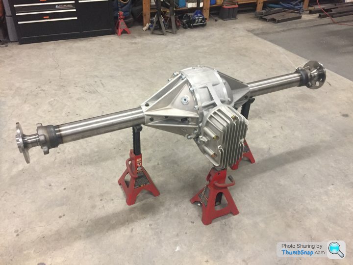
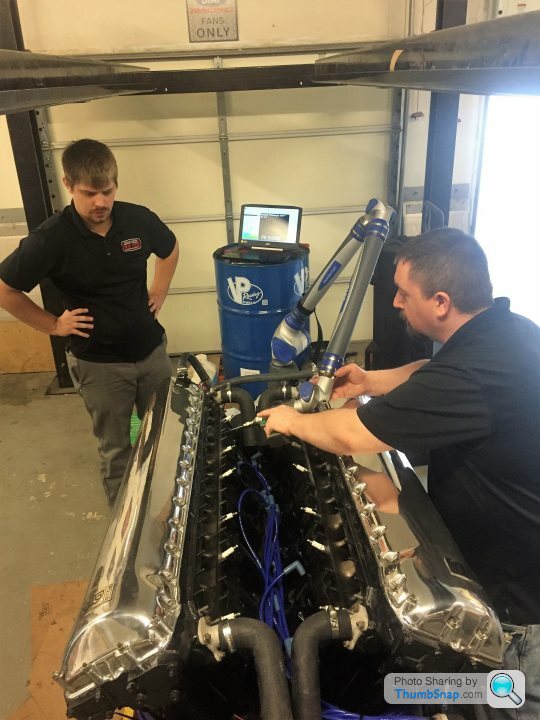
Time for an update. I'm slowly getting the engine to look good - found a spare Merlin cam cover to replace the hideous Meteor one, and had both polished. I went through nearly 100ft of plug wire to get rid of the old, rigid conduit-type plug leads and plugs. I'm getting a custom intake built for the six 48IDAs, and the guys came round recently with their Faroe Arm to digitize the top half of the engine in preparation for building the intake. On the chassis side, the rear end arrived, so I fabricated spring perches and shock brackets before installing it in the frame. It's a Winters 'Extremeliner' quick-change, currently set-up for a 2.00:1.00 ratio to accommodate the low revving engine. I had a set of Andre Hartford friction shocks built and these also arrived recently so I've installed them too. These are the exact same shocks that RR was using back in the twenties, amazing that they're still in business! The C-6 transmission will arrive next week and then I can begin figuring out what the adaptor should look like. Once the engine and trans are mated then I'll drop it into the frame. Hopefully by the Richard Brothers will have finished the 21" wire wheels and Blockley tyres.
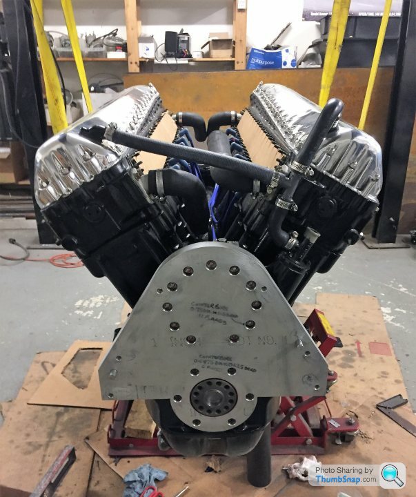
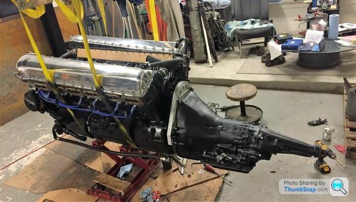
the modified/beefed-up C6 transmission finally arrived. I designed an adapter plate and had it water-jetted out of 1" aluminium. This was then machined to take a bronze thrust bearing and oil seal for the crankshaft snout extension that was tapped-out for the C6 flexplate. The thrust bearing is actually for insurance only, because the snout adapter fits into the crank really tightly and won't move around (but, just in case...). Everything went together remarkably easily. The only small glitch is that the starter motor slightly interferes with the side of the engine block. I U/T'd the block casting's thickness and it's around 1/2" thick. I initially thought about simply grinding off a bit of block to make things work, but I reckon my best way forward is to get a new motor mounting flange machined for the starter that will move it out and up by around 1/4?. The 21" wire wheels with 7.00 x 21 Blockley tyres are finished and on their way. These will let me roll the chassis under the suspended engine-trans combination and get them into the chassis. Then it will be looking almost like a car, and I can start on the headers and exhaust fabrication, which looks to be a tough job.

Gassing Station | Readers' Cars | Top of Page | What's New | My Stuff