Pembleton mkII - Tin Tub
Discussion


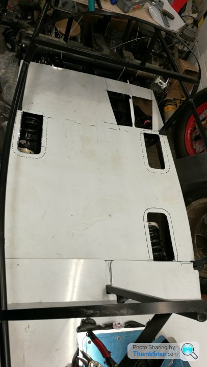
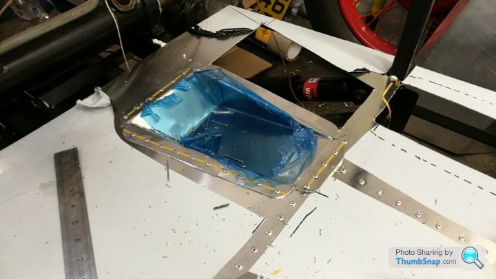
With the hole for the heel recess now cut out the floor was now ready for fitting. I wiped down the chassis with some isopropyl and put a healthy bead of SikaFlex 552 structural adhesive on all the mating faces of the chassis with the floor. This isn't required in the (basic) instructions, but I want it to be strong, feel sound and waterproof.
Main section bonded down
Then the rear bulkhead and trunk floor
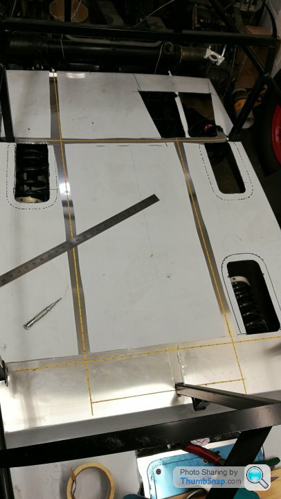
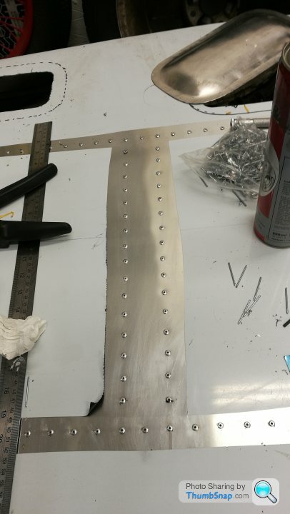
I then started marking up for rivets. I bought some 3mm masking tape to ensure I got a neat straight line and decided in 1" spacing...
Time to drill them holes! The amount of drill bits I went through was frankly a joke, either from snapping, or just blunting. Thankfully 1/8" HSS drill bits are only a few quid for 10. I might get the stubby double ended ones next time.
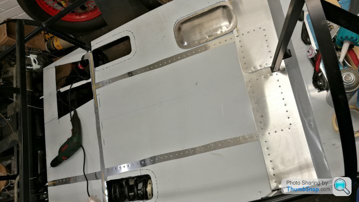
I drilled the 170 odd holes and put the rivets in...

All lined up, ready to pop like a druggy at a rave!

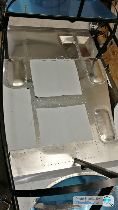
I also fitted one of the heel recesses. I didnt fit the other one yet as I need to have a rethink on my fuel line routing as I planned to have it right where I want the heel recess...
Main section bonded down
Then the rear bulkhead and trunk floor
I then started marking up for rivets. I bought some 3mm masking tape to ensure I got a neat straight line and decided in 1" spacing...
Time to drill them holes! The amount of drill bits I went through was frankly a joke, either from snapping, or just blunting. Thankfully 1/8" HSS drill bits are only a few quid for 10. I might get the stubby double ended ones next time.
I drilled the 170 odd holes and put the rivets in...
All lined up, ready to pop like a druggy at a rave!
I also fitted one of the heel recesses. I didnt fit the other one yet as I need to have a rethink on my fuel line routing as I planned to have it right where I want the heel recess...
ivanhoew said:
Very interesting thread thank you for your diligence in updating it ...bookmarked !
Thanks, this is the only place where I'm doing a build log and I'm trying to keep it as thorough as possible with plenty of pictures. I feel like I'm on a bit of a roll now, although once the lower floor and bulkheads are in I'll have a bit of a lull again as I get into working out the handbrake, pedalbox and gear change.
Once that's done I'll be cracking on with some further aluminium work.
The rear deck is now bonded in and secured with Clecos.
I've marked up where the rivets will be going too...
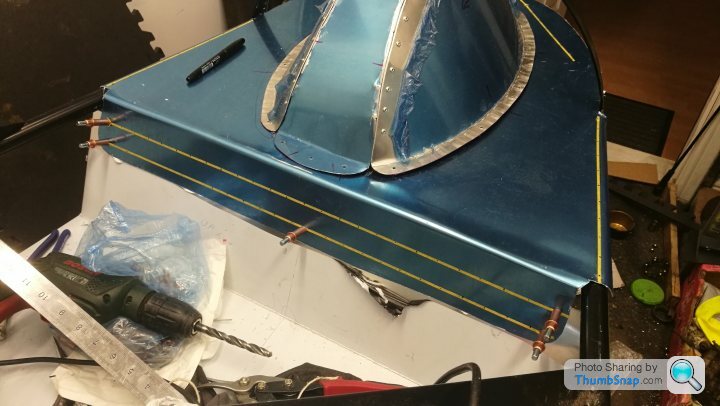
The armadillo is still loose and will be fixed later.
I'm also not 100% happy with the span of unsupported material in the middle of the floor and it does have a bit if flex, so I've decided to fold up a channel in aluminium and bond/rivet it to the floor from the underside.
This will add a shed load of panel stiffness to it.

I've marked up where the rivets will be going too...
The armadillo is still loose and will be fixed later.
I'm also not 100% happy with the span of unsupported material in the middle of the floor and it does have a bit if flex, so I've decided to fold up a channel in aluminium and bond/rivet it to the floor from the underside.
This will add a shed load of panel stiffness to it.
I finished off drilling and setting all the rivets for the rear deck area...
I probably put about 100% more rivets than required, but it looks cool and its strong


Next up was the channel for the floor as mentioned above.
I marked up and folded the channel in aluminium by clamping in timber and knocking over.

I then finished one of the ends by cutting and folding over...
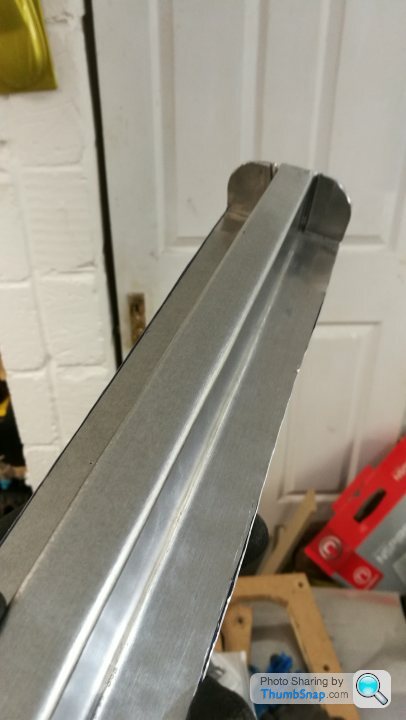
Once I'd marked up the exact width, the other end got the same treatment...

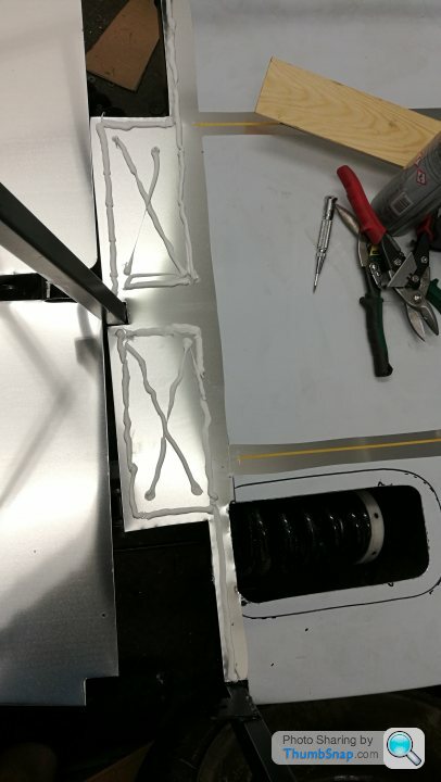
Another healthy bead of structural adhesive and pushed up from below. I then marked up and drilled the rivet holes.

Once all fully riveted to the floor I drilled the tab flanges and riveted to the chassis rails
I probably put about 100% more rivets than required, but it looks cool and its strong
Next up was the channel for the floor as mentioned above.
I marked up and folded the channel in aluminium by clamping in timber and knocking over.
I then finished one of the ends by cutting and folding over...
Once I'd marked up the exact width, the other end got the same treatment...
Another healthy bead of structural adhesive and pushed up from below. I then marked up and drilled the rivet holes.
Once all fully riveted to the floor I drilled the tab flanges and riveted to the chassis rails
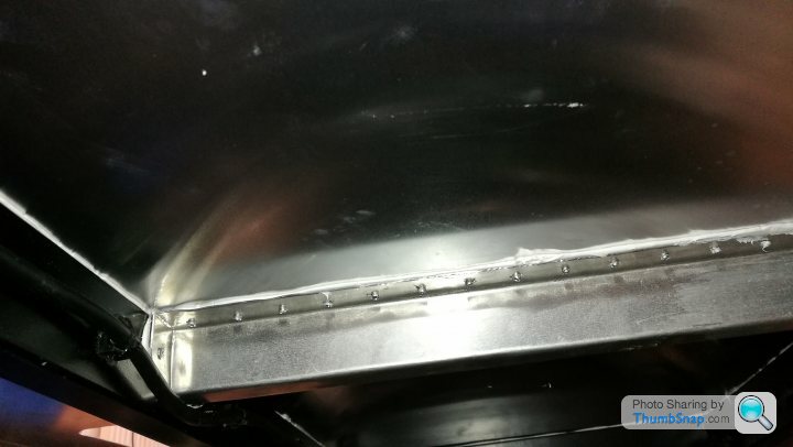
I've also bonded and riveted in one if the blisters (the rear one).
If you look closely you'll see the rivets along the back edge aren't aligned. This is because its right on the edge if the chassis rail and the drill bits kept glancing off and breaking. I think I broke 4 drill bits on these few holes...
It's not the end of the world though as it'll be under the seat...
Retroguy said:
Could you post an image of the rear brake line 'clock spring' arrangement? I thought the original coiled spring was used.... Is it the same thing?
Many thanks in advance!!
Its the same thing. Many thanks in advance!!
The wheelbase is longer than a standard 2cv, so new brake lines are required anyway. I've exited the brake line part way through the cross tube though... will try and get some pictures tonight for you.

I'd highly recommend sourcing a 2cv donor first (unless you already have one).
Even super crusty partial ones that are "spare parts only" are getting close to £1k now. By the time all the bearings/seals etc are replaced and parts refurbished then it could be expensive. I was fortunate with my donors.
Even super crusty partial ones that are "spare parts only" are getting close to £1k now. By the time all the bearings/seals etc are replaced and parts refurbished then it could be expensive. I was fortunate with my donors.
Retroguy said:
I got my donor a few years ago and completely stripped/cleaned/refurbished most of the components I need. Rick Pembro refurbished the gearbox for me. I split the original engine and it's just about ready to re-assemble (pending new seals etc). I modded the rear swing arm, then put everything on hold a couple of years ago but am now ready to proceed.
I've got a list of 2CV parts that I need to buy to complete the refurbishment proper, which I hope to source from Der Franzose and Burton (carb kit, brake components, suspension components, clutch, 123 ignition, etc).
Your build is inspiring me!!
One of my problems is indecision.... For example, I'm not sure whether to go short or long wheelbase (am just over 6ft, medium build) and can't make up my mind on original or wire wheels.
Its borderline if you're 6ft, I'd probably go lwb, but my dad is 6ft and he's okay in Victoria (swb). I have one of each here if you want to try out for size! I'm in Northampton.I've got a list of 2CV parts that I need to buy to complete the refurbishment proper, which I hope to source from Der Franzose and Burton (carb kit, brake components, suspension components, clutch, 123 ignition, etc).
Your build is inspiring me!!
One of my problems is indecision.... For example, I'm not sure whether to go short or long wheelbase (am just over 6ft, medium build) and can't make up my mind on original or wire wheels.
I also have a few sets of keihin carbs if you want to go that route?
Wheels are easy to change post build, but means you double up on wings.
I still have the wings and 2cv wheels I removed from Victoria when I changed if you need them? As well as exhaust manifolds and a few other bits!
A lot of people I know have had 2 pembletons. Either bought or built the first one, then built a second one exactly as they want it! I also have one new Burton damper as I bought a set of four if you need. Pm me.
Edited by Ambleton on Wednesday 13th March 10:09
LewG said:
Great work Niall, hope you are well. Did you see the Pembleton on Great British Car Journeys recently? Hammering up a hill on the way to the Isle of Skye I believe, was a good watch
I did not, I know all about it though, that was Tom in 'snotamog. He's a great guy and known to treat the accelerator as an on/off switch! He does some serious mileage in it, circa 15k miles a year I believe!
So the rest of the floor is now bonded and riveted in place with both heel recesses and all the spring blisters.
I've made the steering column hole massively oversize for good reason. Basically if I ever need to remove the steering rack it needs to be slid along its length by about an inch, then rotated about its axis before it can be removed. This means that the pinion needs clearance to do this, hence the huge hole for wiggle room/rotation. The hole was tight on Victoria and I had to get the old tin snips out and was a right ball ache.
I'll make a bolt on cover with a tighter hole to the column.
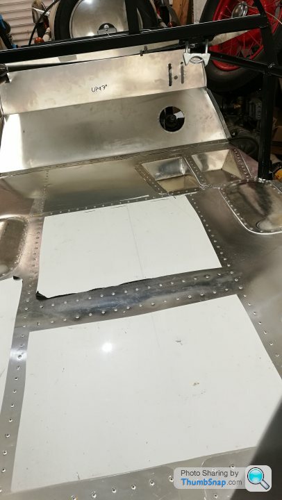
I also made the top of the footwell area that will form the platform for the handbrake and gear lever mechanism, as well as all the other electrical equipment and glovebox base.
I made a hatch in order to access the pedalbox, gear and throttle cables from above. Its a proper effort to change/mod these without this as I've learned with Victoria...
This is not fixed in place yet.
I've made the steering column hole massively oversize for good reason. Basically if I ever need to remove the steering rack it needs to be slid along its length by about an inch, then rotated about its axis before it can be removed. This means that the pinion needs clearance to do this, hence the huge hole for wiggle room/rotation. The hole was tight on Victoria and I had to get the old tin snips out and was a right ball ache.
I'll make a bolt on cover with a tighter hole to the column.
I also made the top of the footwell area that will form the platform for the handbrake and gear lever mechanism, as well as all the other electrical equipment and glovebox base.
I made a hatch in order to access the pedalbox, gear and throttle cables from above. Its a proper effort to change/mod these without this as I've learned with Victoria...
This is not fixed in place yet.
Cheers Lew,
I already have my next two projects lined up after this one!
Once the front bulkhead top is properly in place I'll be up to my knees in mechanical bits next. The rear is pretty much done, but I need to fit the gearbox, handbrake mechanism, gear change, front sus and steering arms etc. Then it'll be rolling. Once it's rolling I can then focus in seating and driver positioning.

For anyone interested I've just bitten the bullet and organised for a "long gearbox" to be built. I had one of these in my Lomax and despite what people say, you REALLY DO notice the difference.
This results in the below:
I'll do three comparisons.
Option 1:
Standard 2cv wheels/tyres
Standard 2cv gearbox
5k rpm
1st- 17.22mph
2nd- 33.72mph
3rd- 50.16mph
4th- 68.07mph
Option 2:
19" austin 7 wheels and tyres
Standard 2cv gearbox
5k rpm
1st- 18.25mph
2nd- 35.75mph
3rd- 53.18mph
4th- 72.17mph
Option 3:
19" austin 7 wheels and tyres
Long gearbox (made with 2cv gear set and Ami diff)
5k rpm
1st- 19.43mph
2nd- 38.05mph
3rd- 56.61mph
4th- 78.82mph
With 70mph @ 4560rpm in top gear
Virtually every day there's something coming in the post. Todays delights include some double ended stubby cobalt drill bits (lets see how long these last).

Some fuel tank mounting washers, a new fuel sender (need to check compatibility with gauge)
And some M9 bolts... yes, M9 - thanks a bunch Citroen....
The 2cv is peppered with M7 and M9 fixings, which is a right pain in the arse. Brilliantly the M9 is a 1.25 pitch, the same as an M8, and you can screw an M8 all the way in, but it just feels a little slack, but you cant torque them up.

Still, at least its all metric, could be imperial... or worse, a nix of the two (did someone say M8 or 5/16ths?) What a joke that'd be...
Some fuel tank mounting washers, a new fuel sender (need to check compatibility with gauge)
And some M9 bolts... yes, M9 - thanks a bunch Citroen....
The 2cv is peppered with M7 and M9 fixings, which is a right pain in the arse. Brilliantly the M9 is a 1.25 pitch, the same as an M8, and you can screw an M8 all the way in, but it just feels a little slack, but you cant torque them up.
Still, at least its all metric, could be imperial... or worse, a nix of the two (did someone say M8 or 5/16ths?) What a joke that'd be...
Tonights progress - I'm out of the garage this weekend 
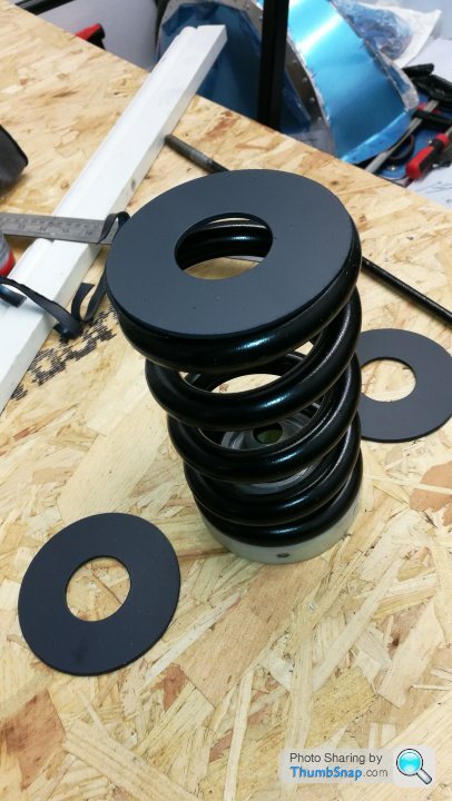
The springs sit in little cups in the chassis. The top half reacts against the chassis rail itself, and the lower part is on a separate bit of steel with a strip seam welded around the seam to create a cup. I'm not a huge fan of this arrangement as there will be uneven loads going into the different parts that form the reacting surface. In order to even out this pressure, I've made some large "washers" that the springs react against. These are bonded into the chassis and create a single flush surface that the force goes through. They are 4mm thick, 100mm OD and 40mm ID.

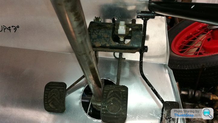
I also trial fitted the pedalbox - we have a clash between the accelerator and the chassis rail. I have another pedal somewhere, so hopefully that one is slightly different, otherwise I'll have to crank it over, which isn't ideal. Its a dual cable pull, so what I might do is remove one of the lugs and make it a single pull. Then go to a splitter nearer the carbs... as yet undecided.
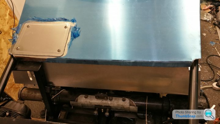
I also fitted the fuel tank, but not the pick-up/sender. As luck would have it, there's a handy hatch that will allow me to fit that later.

I also fitted the front left hub and driveshaft and also trial fitted the handbrake mechanism. I'll have to do some mods to this (make up a new linkage) as its not quite long enough.
I decided to take all my wheels down to a local firm and have them all refinished in a matching colour. The red that I painted the fronts started to chip off quite badly, despite the etch primer, and the rear was bought off the shelf and was painted silver. My rear tyre and tube arrive tomorrow, so hopefully i'll have all the wheels back with tyres on before the weekend.
Retroguy - I did send you an email in return to your PM. Not sure if you've seen it as have had no reply.
Here's a picture of the rear brake line entering the arm (you can just see the coil) then exiting a few inches past the bolt flange..

The springs sit in little cups in the chassis. The top half reacts against the chassis rail itself, and the lower part is on a separate bit of steel with a strip seam welded around the seam to create a cup. I'm not a huge fan of this arrangement as there will be uneven loads going into the different parts that form the reacting surface. In order to even out this pressure, I've made some large "washers" that the springs react against. These are bonded into the chassis and create a single flush surface that the force goes through. They are 4mm thick, 100mm OD and 40mm ID.
I also trial fitted the pedalbox - we have a clash between the accelerator and the chassis rail. I have another pedal somewhere, so hopefully that one is slightly different, otherwise I'll have to crank it over, which isn't ideal. Its a dual cable pull, so what I might do is remove one of the lugs and make it a single pull. Then go to a splitter nearer the carbs... as yet undecided.
I also fitted the fuel tank, but not the pick-up/sender. As luck would have it, there's a handy hatch that will allow me to fit that later.
I also fitted the front left hub and driveshaft and also trial fitted the handbrake mechanism. I'll have to do some mods to this (make up a new linkage) as its not quite long enough.
I decided to take all my wheels down to a local firm and have them all refinished in a matching colour. The red that I painted the fronts started to chip off quite badly, despite the etch primer, and the rear was bought off the shelf and was painted silver. My rear tyre and tube arrive tomorrow, so hopefully i'll have all the wheels back with tyres on before the weekend.
Retroguy - I did send you an email in return to your PM. Not sure if you've seen it as have had no reply.
Here's a picture of the rear brake line entering the arm (you can just see the coil) then exiting a few inches past the bolt flange..
GOOD NEWS!
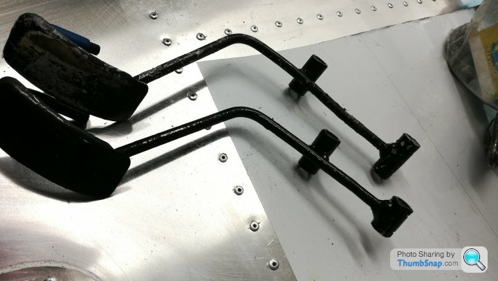
I rummaged around in the belly of the garage and found my other throttle pedal. This one was the one modified by PMC to go with this chassis, so I'm glad I found it.
Photos for comparison:
You can see that the lever to the cable pull is shorter and also the barrel at the top that takes the ends of the throttle bowden cables is also substantially narrower. Trial fit now shows a decent amount of clearance to the chassis rail.

My tyres are arriving tomorrow and aim to have it rolling asap!
I rummaged around in the belly of the garage and found my other throttle pedal. This one was the one modified by PMC to go with this chassis, so I'm glad I found it.
Photos for comparison:
You can see that the lever to the cable pull is shorter and also the barrel at the top that takes the ends of the throttle bowden cables is also substantially narrower. Trial fit now shows a decent amount of clearance to the chassis rail.
My tyres are arriving tomorrow and aim to have it rolling asap!
Gassing Station | Readers' Cars | Top of Page | What's New | My Stuff