540HP NA 7L V12 3 seater
Discussion


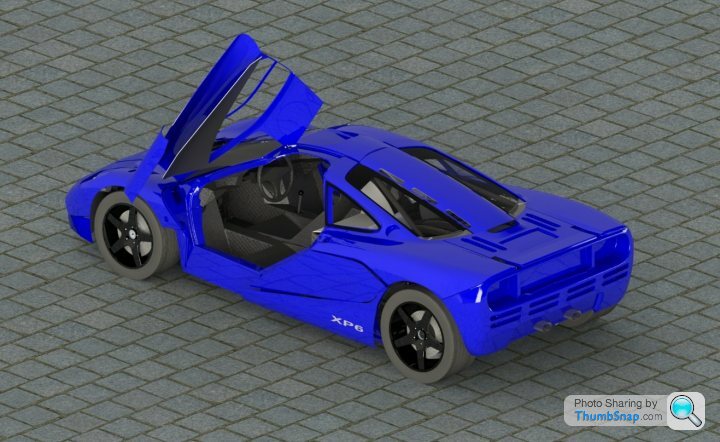
From this angle you can see the passenger shoulder retractor slots clearly.
The pedals themseves are going to be custom made with a pedal ratio of between 6-7 and using Tilton remote reservoir & 75 series master cylinders in a dual circuit layout with a tilton balance bar assembly allowing f/r balance once track testing starts. The reservior is positioned higher than all the caliper bleed nipples.
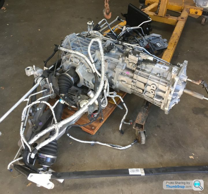
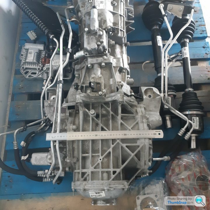
Photo of the newest acquisition for the project - an MEK transaxle from a C7 Z06 with a torque limit of 860nm. It is fairly obvious from this shot why the weight distribution of the car is at 45F/55R, the rear axle is a long way from the input shaft. By nature of their transverse position both engine bellhousings nestle in nicely to the transmission front mounting plate. I needed a real sample to reverse engineer from so that the CAD models could be completed - photos and internet info are not good enough for this task.
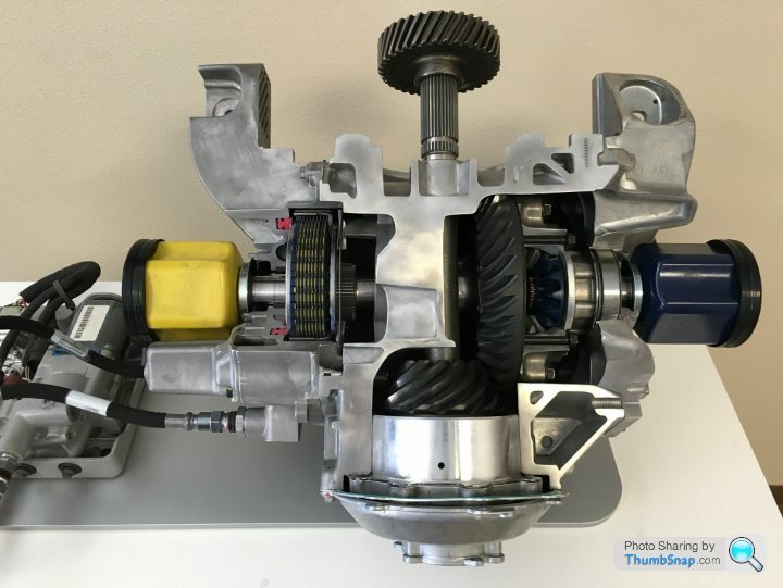
These units have an electronically controlled differential that can change from open condition to locked (0 to 100%) in 150 ms (.15 sec) . The diff when locked up to 100% corresponds to 2000 Newton-meters (1475 ft-lbs) of break-away torque (every 1% is 20 Nm (14.75 ft-lbs)). So at full lock it would take 2000 Nm of torque between the wheels to make the clutches slip. For reference a C6 Corvette mechanical differential clutch pack has around 120 Nm (88 ft-lbs).
Being able to tune the open setting on corner entry allows easy influence of the rate of yaw – what GM term Yaw Damping. Given how centralised the masses are the low polar moment of inertia could take a bit of getting used too – during the initial testing the diff can be set higher to give less snappy and responsive turn in – it will have tunable understeer. The advantage is a few laps later you can tweak the setting from the drivers seat to what feels best.
When heavily on the throttle, the diff can lock up more and shift torque from the inside wheel to the outside wheel. This has the combined effect of minimizing or eliminating inside wheel spin, but it also controls how much it feels like the car turns with the throttle.
Here is a cutaway showing the diff internals, the hydraulic pump on the left pressurizes a piston that clamps the clutch plates - no springs required.
Edited by F1natic on Saturday 16th May 08:56
sheepdip said:
Why not remove the clutch's from the engines and then add a single one to the gearbox?
A good question Sheepdip, that way would be simpler mechanically. However I have 3 main reasons for not going that way;1) Packaging - I am really struggling to cram everything into the short wheelbase as it is, and the clutch inline with the transaxle would add more length forcing the rear wheels back. Currently the dual mass flywheels and standard honda clutches fit nicely into the area where the support bearing housing for the pinions reside, its now quite compact and robust
2) Harmonics - I do not want to direct couple the crankshafts using gears as I have seen some twin engine attempts where crankshaft oscilations due to the power strokes literally smash the gear teeth to pieces, having the dual mass flywheel on each engine insulates the pinions from those distructive angular oscillations.
3) I really want to be able to switch off one engine at will. With the weight at approx 1350kg and clean aerodynamics and now a 7 speed gear box with 3 overdive ratios the power required to cruise at the speed limit will be low - so fuel economy should be minimised. I don't need a 7L engine for the majority of use and even though I am lugging around an extra 150 kilos - when the road and traffic conditions suit I can bring the suspended motor into play and consume all the fuel I had been saving earlier! It will be like having a large passenger who can pedal very hard when asked too.
Edited by F1natic on Monday 4th May 01:11
ivanhoew said:
Mr Natic ,
Great project , in case it helps,here's a pair of straight 6's running 45 degrees offset ,with and without silencing ,..to give you an idea of the sound with that degree split .
https://www.youtube.com/watch?v=x0hdoMj1lDU&t=...
regards
robert
Robert, your project is exemplary. Also your videos are great, thanks for the link, looks like you are having a lot of fun now that she is under her own power. I will probably do the same dance when I get my setup running for the first time too. In all my years of searching the internet for twin engine setups I still managed to miss an epic project such as yours.Great project , in case it helps,here's a pair of straight 6's running 45 degrees offset ,with and without silencing ,..to give you an idea of the sound with that degree split .
https://www.youtube.com/watch?v=x0hdoMj1lDU&t=...
regards
robert
If anyone knows of any other successful twin engine projects (or failures, they are more informative!), I am always very interested to know the technical details.
Edited by F1natic on Monday 4th May 07:25
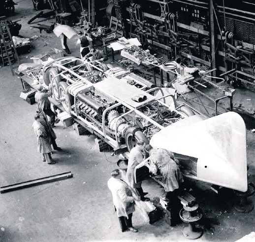
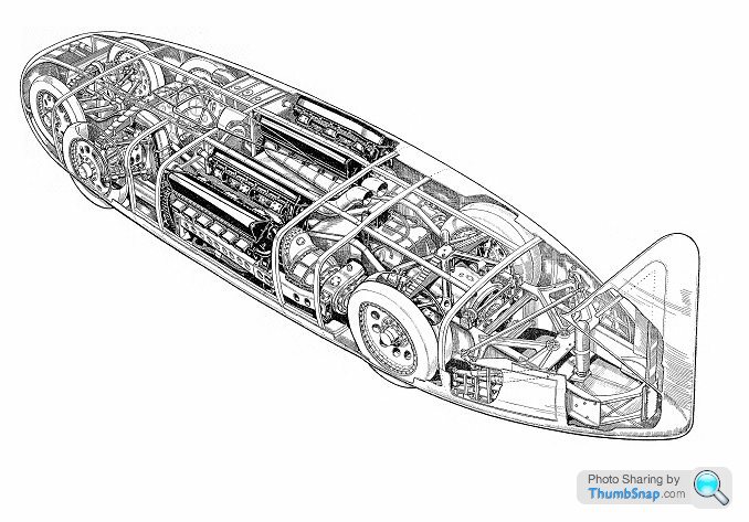
No matter how much research you do, there is always the chance of uncovering something special related to a project. This great example of engineering resourcefulness being used to achieve a goal comes from 1937. I knew nothing of George Eystons' "Thunderbolt" before YouTube kindly recommended a video about it.
It used a pair of 36.5 litre supercharged Rolls Royce R V12's putting out 2,350HP each, fed through a 3 speed gearbox to the rear axle (the gearbox alone weighed a ton, the whole vehicle ended up at 6 tons). In top gear the clutches were bypassed by a dog lockup mechanism that initially wasn't able to cope, but with some field trials and modified parts it went VERY well, as you would expect. What a beast.
It used a pair of 36.5 litre supercharged Rolls Royce R V12's putting out 2,350HP each, fed through a 3 speed gearbox to the rear axle (the gearbox alone weighed a ton, the whole vehicle ended up at 6 tons). In top gear the clutches were bypassed by a dog lockup mechanism that initially wasn't able to cope, but with some field trials and modified parts it went VERY well, as you would expect. What a beast.
Edited by F1natic on Saturday 16th May 00:49
https://www.youtube.com/watch?v=OTY0shFj_C4&t=...
This is the one I watched, it has some brief running shots. Brave timing officals standing out on the course while these things thundered past at 500 kph with a driver who couldn't see due to loosing his goggles. Different times huh?
This is the one I watched, it has some brief running shots. Brave timing officals standing out on the course while these things thundered past at 500 kph with a driver who couldn't see due to loosing his goggles. Different times huh?
Lack of updates due to not having a chance to work on the project - my day job has required full attention post lockdown.
Good news is the gearbox has finally arrived in from the states, but is held up at NZ customs due to spiders in the container - should be available next week after fumigation is done.
Below are the calculated speeds at gear change when at 7500 revs. Top speed goal for the project is 200mph, which is in 5th at max revs. At least we know the body design is capable.
Gear........Ratio.........Road speed (kph)
1st...........2.29..........115
2nd..........1.61..........164
3rd...........1.21..........218
4th...........1...............264
5th...........0.82..........322
6th...........0.68..........NA
7th...........0.45..........NA
The first gear ratio is roughly the same as the 2nd gear in my 2008 Accord which uses the same J35Z2 engine. I have been road testing at low revs/ speed on inclines lugging up the 1600kg. I am confident that the long first gear will be fine with double the torque and less weight, plus I don't mind slipping the clutch (frowned upon practice in a real F1 with its carbon clutch).
Edited by F1natic on Saturday 18th July 10:04
Now that the T.50 design details have dropped it has been very interesting to see how many faults a suposedly "no compromise design" were included on the F1 - I would love to see a fly on the wall doco during the styling decisions and see how much influence PS vs GM had.
Getting compliance with off the shelf items makes sense, however I don't believe that the headlights were from Halfords. Given how much GM espoused the F1 initailly I tend to now take his word with a grain of marketing salt. Interesting to find out that the air vents are from a ford fiesta though.
Also stated that styling changes post tooling blocks were not practical, pretty much puts to bed my hunches about the eyebrow panels above the headlights, however in my opinion the rear spine is not too wide or disproportionate. I would love to spend an afternoon talking to PS about where he wanted to go with the design.
The luggage loading issue is not one I had ever heard of or imagined, although the luggage getting cooked will still be a challenge for the T50. I only have about 120mm between the harmonic balancers and the side panels so no problem on my car as there won't be any storage on the sides. For long road trips I have contemplated designing a custom aerodynamic suitcase with a quick release - a sort of "Drop Tank" so that the car has external luggage capacity. Easy to leave in the accommodation while exploring the roads around the destination unhindered - I am looking at you Queenstown.
Agreed. Visionary people often have a no compromise attitude as that is a critical characteristic required to bulldoze things through and get the result they want, and in the end the victory or defeat rests on the team leader. But it is a team that usually builds these things, and the results from effective teamwork are always better than single minded obsession.
firemunki said:
I love how the awesome engineering and CAD work was all topped off with I tested it with some Lego!
Gotta ask (and feel free to not answer) what is your day job cos this is many (many many) leagues above people building kit cars/track cars/classic rebuilds.
My day job is a mechanical design engineer at one of the few remaining foundries in NZ. It took many years of careful career steps to make the opportunities avail themselves. A large part of my work is printing and casting 3D prints of prototypes for our customers, so all those skills are directly transferrable to the project. I am very fortunate that my employer is fully supportive of my project as I am fairly obsessive about it (as one has to be, see point above!).Gotta ask (and feel free to not answer) what is your day job cos this is many (many many) leagues above people building kit cars/track cars/classic rebuilds.
The complexity is not much higher than other projects, but ask me that once I am done. The ECU is a fascinating field and there has been huge progress recently on the Speeduino front - Josh has been working on the Dropbear unit which will probabaly be a better ECU for the project as it has the capacity to run full sequential on 8 cylinder applications. Regardless of the ECU type I will need a pair of them.
underwhelmist said:
I've just caught up with this whole thread, I hadn't seen it before. What an awesome project! It put me in mind of John Britten's bikes - he wasn't one for following convention either, there must be something in the water in NZ.
https://en.wikipedia.org/wiki/Britten_V1000
The final paint colour scheme I am probably going to go with will be a hommage to the V1000, I used to help out in the Ruapuna pits on a mates bike at the bears racing in chch at the time they were racing it. I will never forget seeing Andrew Stroud entering the straight, drifting under power, leaving a huge black mark every lap then lifting the front wheel almost fully down the straight. Was a magnificent sight and sound, having fun with engineering is what inspires me. Spent a summer holiday at engineering school in the windtunnel finishing off a students project for the Britten team so got to meet a few top blokes, Dr Murray Aitken was always gracious with his time, and in my opinion the unsung hero is Mike Brosnan, whose own bikes were fantastically crafted machines.https://en.wikipedia.org/wiki/Britten_V1000
Edited by F1natic on Saturday 8th August 02:35
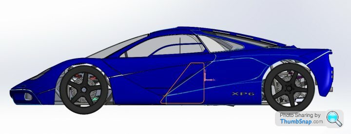
The 65 litre fuel tank (outline visible) is sitting nicely in the middle of the car. The route the pipe takes from the normal fuel filler cap position to the tank is a bit convoluted and not very elegant - Unfortunately someone has stuck a bloody motor in the way of doing a simple straight connection.....
Edited by F1natic on Friday 14th August 12:39
ivanhoew said:
Nice shape !
Thanks, I am still undecided if it is a shameless ripoff or respectful homage...if I can lay 50ft black lines on the road then I am leaning towards the latter.I am so impressed you have a dyno in your shed, very useful. I had never seen anyone find TDC with a whistle before either, you have lots of cool tricks up your sleeve. I am also using tunerstudio, but running the speeduino ECU. Over the last few months Josh has been putting out new videos detailing the circuits and programming, so will be doing a lot more electronics and wiring than welding over the next few months.
Today I am compiling the appendices for the 4B design submission to the LVVTA. I will be applying for the build approval in the next few weeks as everything except the windscreen wiper arm mechanism is fleshed out in enough detail now.
Suspension and frame loads are not specified by the NZ regulatory body, however I based my analysis around multiple sources;
1) Costin and Phipps appendix 1 (oldie but a goodie)
2) Load case table from the ULSAS project that Lotus published (the most up to date reference)
3) an old SCCNZ scrutineering document (lots of really practical old school tips littered throughout)
4) 3rd Edition Australian Design Rules for torsion and beaming (68kg per passenger seems an underestimate for average weight these days.....)
Load cases were;
Square on Curb Strike = 0.5g in X, 3g in Z - applied at tire contact patch (analysis of 2 cases - forward motion and front axle, rearward motion and rear axle)
Lateral Curb Strike = 1.5g in Y, 1g with weight transfer in Z - applied at wheel rim lower position - front and rear
Heavy Braking = 1.1g in X, 1g with weight transfer in Z - applied at tire contact patch
Severe Pot Hole = 1.5g in X, 4g in Z - applied at tire contact patch
Diagonal bump = 4g in Z - applied at tire contact patch (for those unexpected offroad excursions where velocity outpaces lateral grip)
6G at all shock mounts in direction of action at ride height
Static wheel loads are 338kg each at the front, 422kg each at the rear, in Gross Mass (GMV) condition. The forces the frame and suspension have been calculated to withstand are the acceleration values and directions above multiplied by the wheel loads (some are amplified by weight transfer also). These studies were conducted on the bare steel frame, which in reality will be stiffened and strengthened by composite panels, however I do not have the skills to study that more complex structure - so will measure the end result and compare to the bare frame design calcs to get the final signoff by the certifier.
ADR torsional compliance requires no permanent deflection after applying a torque = track x 0.25 GVM * g = in this case 6253Nm. The frame model deflected 0.53 degrees at this theoretical load, so expecting >12500Nm/degree final frame stiffness, which is fine for a road car with supple suspension.
Edited by F1natic on Sunday 23 August 10:14
curb weight is going to be 1300 to 1350 kg with driver and fuel (No aircon, no radio). I have not modelled every bolt so added provisional values for some systems, but all the big parts are accounted for. The total weight cannot exceed 1500kg or the donor corvette rear axle is overloaded (1870lbs according to General Motors) and i will not get certification signoff, so at target weight can carry a couple of passengers without issue.
The drivable test mule sans bodywork is 1100kg, which is based on CAD model sums. Traction will be tricky, but now that I have the ediff, things will get interesting on that front.
The drivable test mule sans bodywork is 1100kg, which is based on CAD model sums. Traction will be tricky, but now that I have the ediff, things will get interesting on that front.
Edited by F1natic on Monday 24th August 19:38
A big inspiration (and cautionary tale) for me as a young lad was the tale of the Giocattlo effort by Paul Halstead in the late '80s. I owned an Alfa sprint for a few years with the idea in the back of my head of making a lightweight version using a lexus V8, but the transaxle was always the issue. However today while browsing an article on the old cars I discovered his new adventure, and I thought I was a bit "eccentric" for going twin engined....
Apparently the Giocattolo “Marcella” is underway. It is a midengined 3 seater design, although it has a canopy entry system.
Long term the vibration on the cranks from the high power LS engines may cause gear reliability issues with this arrangement (same as it did for the LearAvia Lear Fan 2100), and is one of the main reasons I didn't use this configuration, although its common on tractor pull designs.
Its not my cup of tea, but I admire his budget!
To save you searching - https://www.go2hal.com/
Edited by F1natic on Saturday 29th August 08:50
Those things revved so hard and sounded really good, and the 2.5 put out 200hp, so x 2 would be good. Are they still available? For me it always comes back to $/hp - hence going for the bolt-on solution. I have seen a guy spend a literal fortune to put a 4 valve head on his rover v8. Just because you can doesn't mean you should (oh man I bet those words come back to haunt me in the future!)
Edited by F1natic on Saturday 29th August 09:31
Hinge axis proved quite time consuming to lock in, done now so can detail the complex lower hinge and door latch tomorrow.
Mucking around with render settings, result below. Brake calipers and throttle pedal are not shown because they are not modelled yet - same goes for the internals of the door.
The sill is high to increase spaceframe stiffness and side intrusion resistance.
Mucking around with render settings, result below. Brake calipers and throttle pedal are not shown because they are not modelled yet - same goes for the internals of the door.
The sill is high to increase spaceframe stiffness and side intrusion resistance.
samoht said:
It seems that some engineers in Hiroshima had the same dream as you, only for it to be rudely punctured when the bubble burst:
https://jalopnik.com/it-was-japan-s-most-daring-ca...
Thank you for that link, it was a fascinating read. I had never heard about the Amati V12 or the M2 factory, very cool concept. Always loved the Autozam AZ-1, cool little car. https://jalopnik.com/it-was-japan-s-most-daring-ca...
Edited by F1natic on Saturday 29th August 22:56
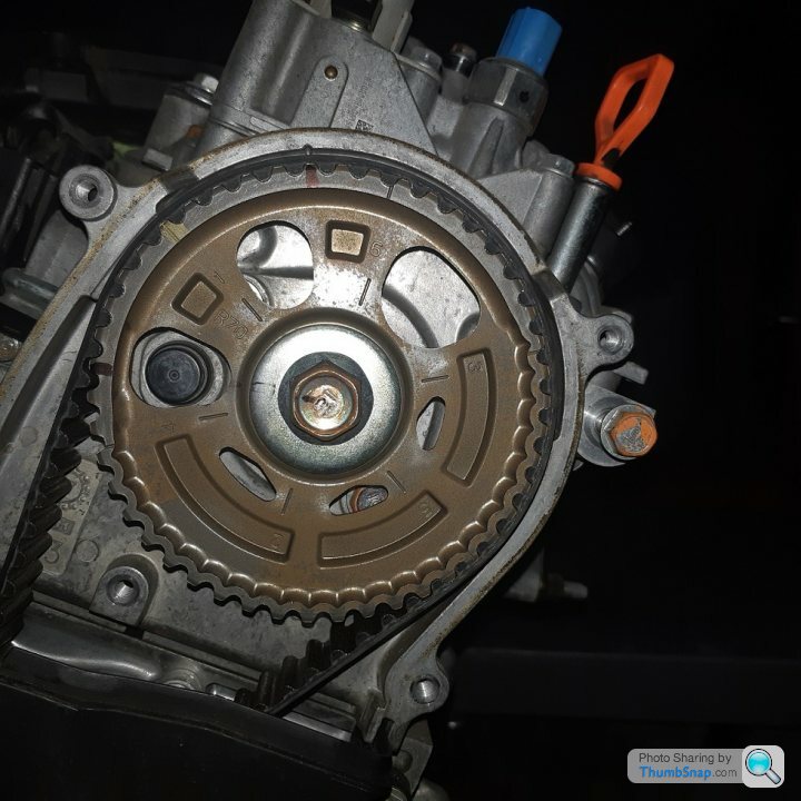
Doing the prep work to decode the cam signal positions that will allow the ECU to find the true position of the test motor during cranking/running. The Hall sensor for the cam (CMP) is the round object in the cutout at the 9 o'clock position. Theory is that the ECU will read the cam signal whenever it detects the crank trigger ( a 2 tooth gap on the 60 tooth wheel bolted to the crankshaft - so occurs every 360 degrees). The cam signal will either be on or off depending on the true position of the motor set by the blocks on the back of the cam pulley shown. The ECU can't tell the difference between TDC on 5 or on 1, but its important if you want to run sequential fuel injection and ignition. The Speeduino is currently limited to 9 timer channels so I am going to use 6 for fuel injection and 3 for ignition. The fuel will be sequential, but the ignition will be batch fire (where the ECU fires 2 spark plugs at once, one of which will be a cylinder on its exhaust stroke)
Gassing Station | Readers' Cars | Top of Page | What's New | My Stuff