540HP NA 7L V12 3 seater
Discussion


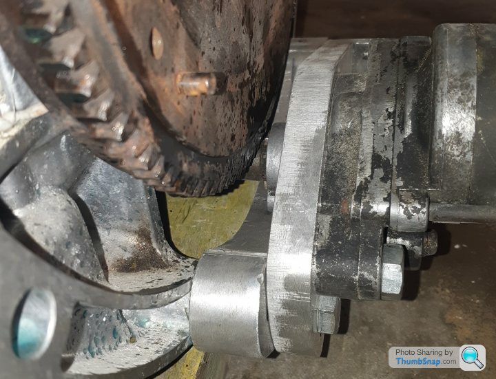
Turns out that C6 Z51 drive shafts fit the output splines of the TR6070 box, which is an unexpected bonus as I can put off upgrading the rear drive hubs to C7 units until I have put a few miles on the test mule. Unlike the C7 units the C6 driveshafts are equal size, which can contribute to diff destroying wheel hop.
After reading the IMechE paper by Steve Randle about the concept and design of the McLaren F1 suspension systems* I was hoping to achieve a steering ratio of 18:1. However reviewing the Titan datasheets for "off the shelf" pinions and racks has resulted in the closest ratio that works with the corvette front spindle steering arm length giving around 20.6:1 - which is the same ratio as the early Honda NSX.
I have read on the internet that the NSX initially feels like it steers too slow, but not having driven one I will trust Ayrton Senna, who had no issues hustling the NSX around Suzuka. Since most high speed driving is done with less than 5 degrees of road wheel deviation this results in 106 degrees of steering wheel rotation at the 20.6:1 ratio (or 2.55 turns lock to lock). By comparison the steering wheel angle with a very fast 17:1 ratio would be 90 degrees.
Given this will be an unassisted rack I am happy to start off with the higher ratio rack. Tire stiffness has a large effect on steering feel so lots of room for development**
- - IMechE paper C466/007/93
- - the process of throwing money at problems until they go away
Edited by F1natic on Saturday 19th September 05:28
Thanks for the feedback, always appreciated. I took an MR-S for a test drive on my reference road* and to date it was the best car I had driven for front end response, although it is also lightweight, has small wheels and a short wheelbase.
Double checked the options from Titan and will go for the middle of the road ratio using the 8T 14 DP pinion in an eccentric rack, which gives a steering ratio of 17.5:1. Changing to the 9T 14DP will give 15.5:1 and 7T 14DP will give 20:1, so a good range of options for the future without huge expenditure, given the eccentric housing allows the pinions to be changed without too much hassle.
Early thinking was slower steering might be best for a manual steering setup in a 200mph capable car, to reduce the sneeze and crash effect, however given the car will be a daily driver and used in the legal speed range slow steering may not be as desirable. Having a faster rack may be of great value given the rear end will have a tendancy to step out with 688nm on tap.
Also was fortunate to experience a 350 mile dawn raid last weekend in a very capably driven 2018 Carrera T, with around 480hp. It recalibrated my brain as to the benchmark for handling I would like to achieve for tight and bumpy New Zealand back roads. With rear steering and power assit the ratio gets down to 12.5:1, but is 15.0:1 in centre position. It worked really well.
- - the one outside my house
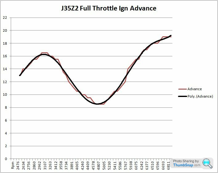
Since the Auckland harbour bridge was damaged and commuting has been a chore I took the scenic way to work this morning. Lots of quiet country roads to allow recording of the ignition advance curve for the stock Honda ECU at 100% throttle, up some reasonable inclines to give a decent resistive load and thus a longer sampling window, using an OBD2 scanner/logger. It seems the ECU reverts to these values once more than 25% throttle is used. Interesting to see the effect of the VTEC on the advance required.
Robert, it's a naturally aspirated engine running on 91 grade fuel with stock 10.5:1 cr and factory ecu settings, and those numbers where recorded with multiple runs using 100% throttle command. Unfortunately I cannot see the throttle readings when it's set to record and therefore to get the curve I used WOT. Do you know a clever way to record the factory ECU outputs and build the full curve? My scanner is very basic. I am going to be using alpha-n strategy in Tunerstudio for the test engine, hence once I know what the factory timing table looks like i will only be left with the fuel table to sort. of course all this is when warmed up, cold start enrichment factors will have to be worked out too. One step at a time!
I am fairly sure this is the total advance since the service manual states 10 btdc at idle, scanner say 7 if at rolling idle, and fluctuating around 10 when stationary. While driving on light partial throttle the advance is around 30, will check with a timing light while the scanner is connected to ensure correlation before I carry any assumptions forward to the test engine. Thanks for prompting me to think about that!
I am fairly sure this is the total advance since the service manual states 10 btdc at idle, scanner say 7 if at rolling idle, and fluctuating around 10 when stationary. While driving on light partial throttle the advance is around 30, will check with a timing light while the scanner is connected to ensure correlation before I carry any assumptions forward to the test engine. Thanks for prompting me to think about that!
Edited by F1natic on Wednesday 23 September 19:30
Day job has sucked up all project time hence the lack of updates - no significant progress worth sharing.
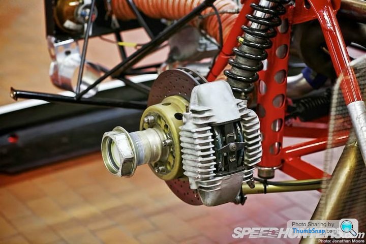
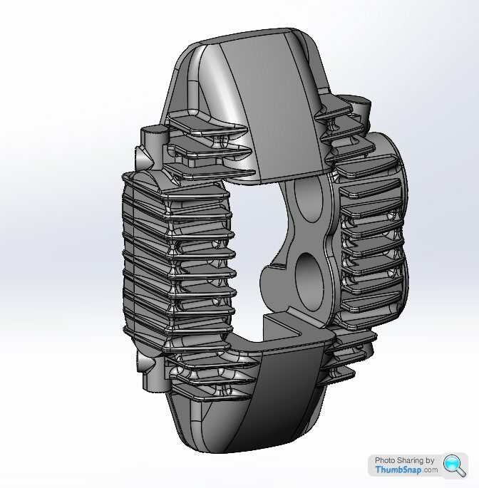
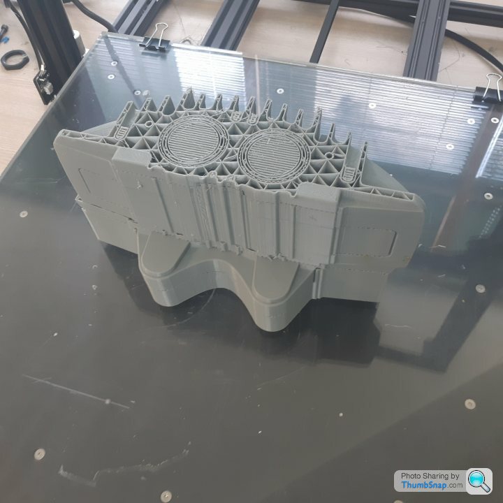
However just completed this job for a client, replicated a Zakspeed style brake caliper. Scanned dimensions using a CMM, then modelled the part in Solidworks to fit the point cloud, 3D printed some patterns and investment cast the result. Luckily the client is patient.
Original part;
Details here; http://www.speedhunters.com/2013/02/fire-breathing...
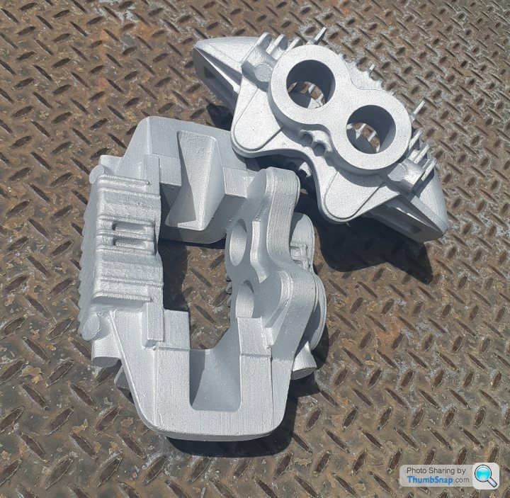
Replicated part;
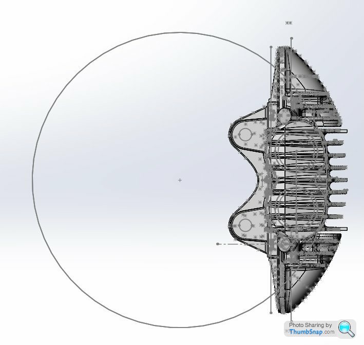
Expecting to release thread related updates later this month once works' silly season is over.
However just completed this job for a client, replicated a Zakspeed style brake caliper. Scanned dimensions using a CMM, then modelled the part in Solidworks to fit the point cloud, 3D printed some patterns and investment cast the result. Luckily the client is patient.
Original part;
Details here; http://www.speedhunters.com/2013/02/fire-breathing...
Replicated part;
Expecting to release thread related updates later this month once works' silly season is over.
Edited by F1natic on Tuesday 8th December 22:17
TekoTime said:
Aha! Finally, something this idiot can give his expert advice on:
Plastic is not a good material for brake calipers. I'd recommend metal, or something.

Agreed, the pedal would feel quite mushy! Plastic is not a good material for brake calipers. I'd recommend metal, or something.
Edited by TekoTime on Thursday 10th December 21:47
Just to clarify these parts were cast in aluminium, as per the genuine articles shown. However rather than sand casting from a cope and drag pattern box we use lost PLA, similar to lost wax casting or investment casting (worth a google). The patterns for these castings were 3D printed and then coated in a ceramic slurry and dried to form a mould. The patterns burn out completely when the ceramic mould is fired. We then poured the molten aluminium into the ceramic mould that has the perfect negative cavity shaped like the 3D print.
It's how I intend to make a lot of my more complex parts for my project, practice is always helpful.
Bodo said:
Nice one! I've recently learned that 3d-printing road-going brake calipers is already possible using SLM - might be interesting for anyone who does small quantities https://conti-engineering.com/highlights/additive-...
A laser sintering metal powder printer would be a great tool to have access too, however they are not common here in NZ. Great for making titanium parts, Rodin cars in the South Island are leading the way - but that option is not possible with my projects' budget. Edited by F1natic on Friday 11th December 02:15
YouTube research has uncovered an interesting implementation of twin radial engines (325 HP each), the Kamov KA 26 dates from 1969-1985. The engine crank output is turned 90 degrees by a bevel gear set to an output flange that incorporates rubber isolators, which then drive the input shafts of the main gearbox. Has to be the ugliest helicopter in the world, but has logged 1000's of hours, and it appears many are still flying in Hungary.
This one probably won't fly again but all the gubbins are there to see;
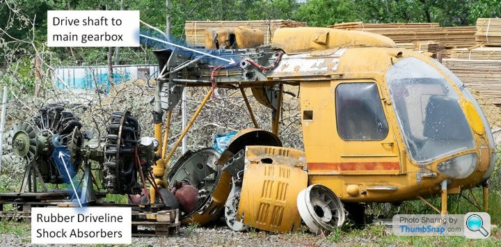
Startup is hilarious as being a radial engine the oil seeps into the lower cylinder when stationary. Firing up procedure is typically rotating by wrench until the cylinder is purged, then run up with compressed air until ignition is sustainable. Its amazing the spark plugs can clear the intense fouling...
https://www.youtube.com/watch?v=myyDoekcf50&t=...
This one probably won't fly again but all the gubbins are there to see;
Startup is hilarious as being a radial engine the oil seeps into the lower cylinder when stationary. Firing up procedure is typically rotating by wrench until the cylinder is purged, then run up with compressed air until ignition is sustainable. Its amazing the spark plugs can clear the intense fouling...
https://www.youtube.com/watch?v=myyDoekcf50&t=...
Edited by F1natic on Monday 14th December 09:03
roy928tt said:
I've got a Mazda KL powered open wheel racing car here in South Australia (twin turbo dry sump, F1 gearbox) That I'm working on repowering with a Cosworth DFX Indycar engine.
Thanks for your comments Roy, much appreciated. Do you have any pictures you could post of your setup? I am always keen to see how other people integrate their powertrains into their projects, especially when matching components that were never intended to go together! Over the summer break I will be completing the detail design of the bell housings and pumpkin for the T box and casting them all early next year, so any and all advice gratefully accepted. Clutch actuation and how to make it as low a profile as possible is my current learning curve. There is enough width in the engine bay of my car, but I would still like to make it as compact as possible.
Bellhousing will be CC601 Aluminium, T-box pumpkin will be SAE 4130. The pumpkin will be like a diff head, using thin walls that are still very stiff to resist the deflection of the pinions while giving big spigots to align the bellhousings. Might be a bit heavier than required but the goal is for it to last my lifetime.
Edited by F1natic on Friday 18th December 01:03
Great setup Roy, it must be exhilarating to drive. The rear fabricated uprights are superb, I also like the high flow drainage on the radiator. The more I look at the photos the more questions I have!
Any lessons from setting up the dry sump? Brand of pump chosen or reasons? Did you have to modify the existing sump or fabricate a new version? I would really like to get my stage 2 test mule running with dry sumps, which will only happen once I have run around 1000 km through the tbox with the stage 1 stock wet sumps.
Any lessons from setting up the dry sump? Brand of pump chosen or reasons? Did you have to modify the existing sump or fabricate a new version? I would really like to get my stage 2 test mule running with dry sumps, which will only happen once I have run around 1000 km through the tbox with the stage 1 stock wet sumps.
Love the smell of MDF in the morning...
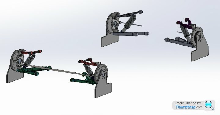
Cutting out some dummy wheels - they will place the C6 spindles at the correct ride height and allow for easy assessment of camber and toe changes through out suspension movement to confirm that the positions of the inner wishbone brackets as modelled in CAD also work in reality.

Cutting out some dummy wheels - they will place the C6 spindles at the correct ride height and allow for easy assessment of camber and toe changes through out suspension movement to confirm that the positions of the inner wishbone brackets as modelled in CAD also work in reality.
This is how I intend for the dummy wheels work, they are the same width at the base as the rim diameter so can be used to gauge toe against factory settings. I want to mock up the suspension pickups before committing the final bracket positions into the design approval document, since that is the document my certifier will judge my final build results against.
Cutout is for brake caliper clearance. The baseline is offset from the "perfect" tire outside diameter to account for the vertical deflection of the contact patch due to the relevant corner load (estimated at this stage since I don't have the final wheel tire combo to load test).
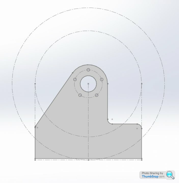
Cutout is for brake caliper clearance. The baseline is offset from the "perfect" tire outside diameter to account for the vertical deflection of the contact patch due to the relevant corner load (estimated at this stage since I don't have the final wheel tire combo to load test).
Totally agree Bodo, fingers crossed.
Spent a few hours prepping the test motor for its imminent first fire-up. Had to understand and measure the crankshaft position sensor (CKP) signal and how the signal is produced on the 60-2 wheel, especially the angular offset between the first tooth after the gap and TDC of no.1 cylinder.
12V or 14V feed makes no difference to the output signal;
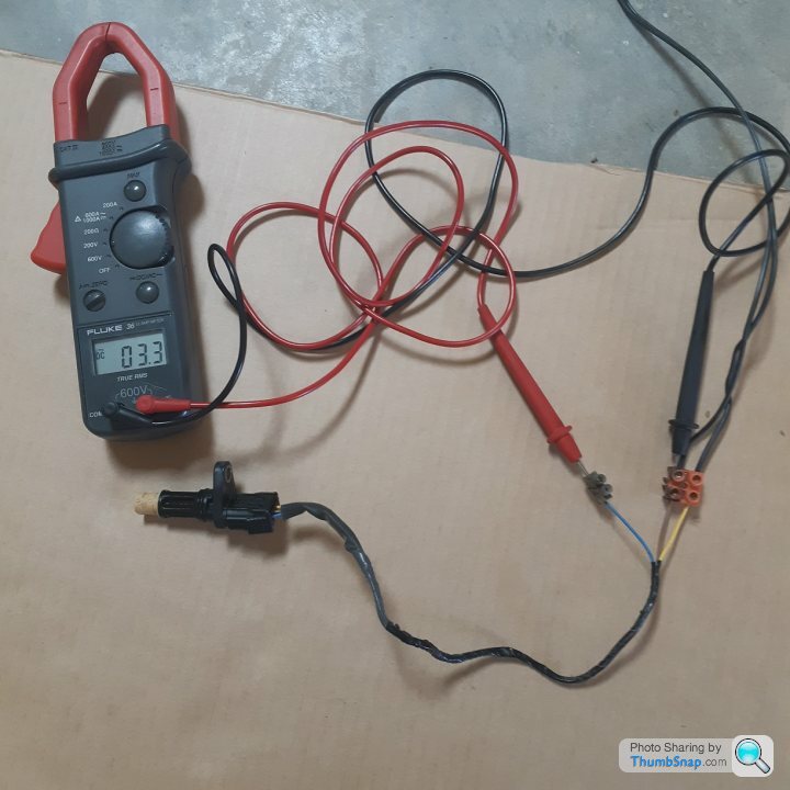
This is the 2 tooth gap that the ECU detects
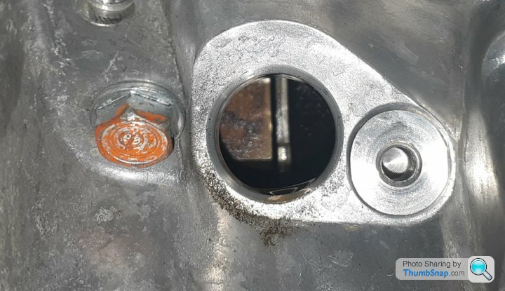
Once the first tooth after the gap is sensed by the hall sensor the signal drops from 3.3V to zero, the falling edge at this angle is used to synchronise the ECU so that the firing of the ignition coils (Coil on Plug type using 5V signal) and injectors matches the true mechanical positions.

Machined the bore of a spare 4 cyl civic flywheel to suit the J35, the bolt pitch is the same but count is different (6 on civic, 8 on the V6) so only 2 bolt holes align, but they will cope OK with the cranking torque, at this stage it is only an unloaded test engine. The starter is from a J30 odyssey, it matches the civic ring gear but turns in the correct direction.
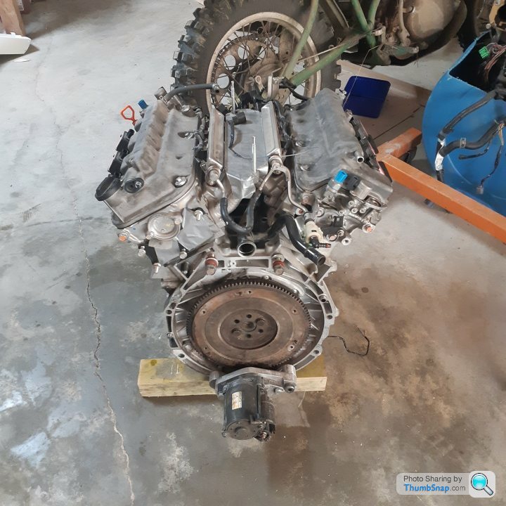
Machined some aluminium plate to make a starter motor mount as I don't have/need the transmission for the V6. It is made in 2 pieces, with an adjustment slot so that the correct ring gear tooth engagement is easily set.
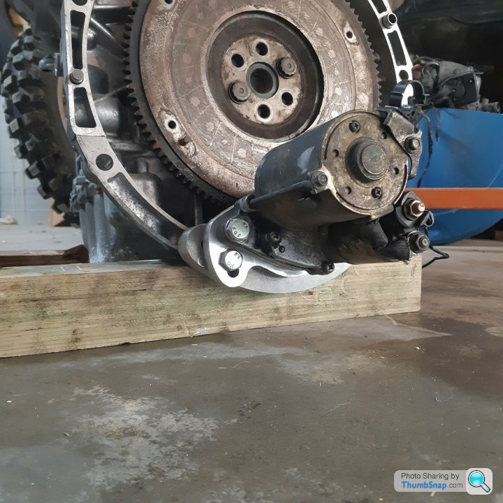
tight fit with minimal clearance on the pinion when disengaged.
The good news is it cranks over strongly - all it needs is a support frame, fuel supply, hacked up cooling system and ignition loom to be able to generate some excessive noise and flames - will post that milestone on youtube
Spent a few hours prepping the test motor for its imminent first fire-up. Had to understand and measure the crankshaft position sensor (CKP) signal and how the signal is produced on the 60-2 wheel, especially the angular offset between the first tooth after the gap and TDC of no.1 cylinder.
12V or 14V feed makes no difference to the output signal;
This is the 2 tooth gap that the ECU detects
Once the first tooth after the gap is sensed by the hall sensor the signal drops from 3.3V to zero, the falling edge at this angle is used to synchronise the ECU so that the firing of the ignition coils (Coil on Plug type using 5V signal) and injectors matches the true mechanical positions.
Machined the bore of a spare 4 cyl civic flywheel to suit the J35, the bolt pitch is the same but count is different (6 on civic, 8 on the V6) so only 2 bolt holes align, but they will cope OK with the cranking torque, at this stage it is only an unloaded test engine. The starter is from a J30 odyssey, it matches the civic ring gear but turns in the correct direction.
Machined some aluminium plate to make a starter motor mount as I don't have/need the transmission for the V6. It is made in 2 pieces, with an adjustment slot so that the correct ring gear tooth engagement is easily set.
tight fit with minimal clearance on the pinion when disengaged.
The good news is it cranks over strongly - all it needs is a support frame, fuel supply, hacked up cooling system and ignition loom to be able to generate some excessive noise and flames - will post that milestone on youtube
LaurasOtherHalf said:
What do you expect the handling of the car to be like with the two outboard engines? Obviously you'll be achieving a very central CoG from front to rear but the weight will be quite uniquely spread across the chassis from side to side, do you anticipate any issues with roll centres?
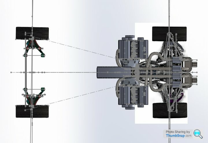
Scary at first! There are so many suspension parameters which will require adjustment to give a stable and benign driving experience, I think that is one of the most challenging aspects of the project, given I don't have a calibrated butt. The engine masses each side are equal distance from the COM of the vehicle, so using the parallel axis theorem (thanks for getting me to dust off my old textbooks!) they have the same mass moment of inertia as an engine twice the size at the same distance. I hope the picture below helps, since the radius from the center of mass is the same for both engine types the equation shows that 2 engines of mass m equals one engine of 2m at the same radius - i.e. 2(mr^2)= 2mr^2 - in the horizontal plane (Yaw).
Yazza54 said:
Roll centres are a function of suspension geometry and ride height not where the weight is placed.
agreed, and the center of mass distance to the roll axis gives the roll moment that the vehicle is subjected to in cornering. I need to examine if the center of mass of 2 equal engines symetrically either side of the centerplane is the same as having one big lump in the middle - have not looked at the S70/2 com to roll centre as I have no data. However I think LaurasOtherHalf is right in that the lateral roll inertia of the 2 engines in the vertical plane might be greater than a centralised lump. So the twin engine layout may be slightly more resistant to roll if its lateral inertia is higher.... It will be not be that different from an F1 carrying a couple of passengers, interesting to see if they reduce the roll response - time to ask Flemke.
Edited by F1natic on Tuesday 29th December 19:41
Appreciate the link, hadn't seen the SLC using a BMW V10 and USD$11K graziano before, will be a very quick car.
The walkaround video clearly shows the old Lotus Europa vunerability, where the expensive gearbox is exposed to damage if you were careless enough to reverse into a kerb
https://www.youtube.com/watch?v=SXhkFQzSnss&t=...
The rear plexiglass looks too close to the rear cylinder inlets, good example of how compromise has to be accepted when doing things unconventionally.
Maybe the next drive could be out to Dunsfold?
Edited by F1natic on Friday 1st January 20:55
I finally got around to listening to the Chris Harris podcast with GM from a few months back, it was really interesting to hear his path through life. I really admire his ability to stick with a vision and get the result across the line - I actually learned a lot from doing the virtual tour of the other vehicles on display in the exhibition. It's said you "should never meet your heroes", which for me is easy as the majority are deceased (John Britten, Peter Brock, Bruce Mclaren, Denny Hulme) so Gordon and Greg Murphy are the only real chances on my list. GM's willingness to help look for a lost cat is an excellent indicator of true character.
Thanks for posting those shots Paul, I like the humble shed that Tyrrell used, reminds me of the old wooden workshop bench that Ferruccio Lamborghini first used, that used to be on display at the factory showroom in St Agata.
Thanks for posting those shots Paul, I like the humble shed that Tyrrell used, reminds me of the old wooden workshop bench that Ferruccio Lamborghini first used, that used to be on display at the factory showroom in St Agata.
Edited by F1natic on Saturday 2nd January 22:51
August 2019 I was hoping to get the design detailing to the stage where I could get the build approval from the NZ low volume vehicle association (4B). It is not mandatory but is highly recommended for a straight run through compliance inspections. The more upfront design that has been reviewed and passed by the technical committee the easier it is for my certifier to rubber stamp the build. Things changed a bit on the design front too, now using the C7 gearbox and diff. I was only expecting the work to take a few months but then 2020 happened and priorities shifted.
Over the next few weeks I am using the summer holidays to finish the appendices for the application, hence the dummy wheels to check proposed geometry. A lot of adjustment is built in, but everything has limits.
This is a tight budget build so it will take a long time to complete, however should see some real progress over the next few months and the test mule rolling early next year.
Very interesting development, thanks for the link. The BRM H16 is a classic cautionary tale to learn from, complexity can multiply design faults.
I often reflect on why the hell am I doing all this work when it could end up being another expensive failure. I really enjoy the design side of the project, but the overall goal is to have a reliable, safe and fun road car that is reasonable to maintain and run, so why do I need 2 engines? And it always comes down to the throttle response. There is no replacement for cubic displacement, and huge torque is what will make the car feel breathtaking to drive. I have always preferred a deep bellow to a high pitch wail from a roadcar engine.
I am very mindful that the cost of development should not exceed the cost of a decent "sensible" sports car like a 911 or an Elise (both ideal for NZ conditions) or the new corvette C8. Overcomplication is a big trap and goes counter to the project goals, anything too extreme or untested has the potential to open multiple cans of expensive worms, which is typically what stalls progress.
It helps to stay focused on the end goal, the final day at the compliance office in 2024. Initially I know driving the car will not be enjoyable, because every noise will be new and I will hypersensitive to anything odd sounding. But once some miles are under the belt and it proves to be trustworthy I will be able to relax and clock up some big miles on it, it is a car I expect to put in my will. I will be very happy if it can accelerate faster than is comfortable, corner in a balanced and stable manner regardless of road surface, stop telepathically and be a comfortable long distance experience for driver and passengers - a true supercar.
I am contemplating once the car is certified to offer it for hire as a driving experience in the south Island, as hopefully by that time the world can get back on its feet and international travel will not be so restricted. We could all do with something to look forward too, don't you think?
Gassing Station | Readers' Cars | Top of Page | What's New | My Stuff