962 recreation with a GT3 Heart...
Discussion


Lets just use the Kit Car industry std (none pressure) sand cast aluminum Material in comparison to Billet.
Cast LM25-M has a Tensile strength of 130 to 150 (N/mm2) (19,000 - 22,000 PSI)
Billet 6061 T6 has a Tensile strength of 290 to 310 (N/mm2) (42,000 - 45,000 PSI)
So lets just say the material alone has twice the strength, so as long as it's comparable in size and dimensions then there's a good safety factor there on it's own. That along with Cad based stress analysis
lets me sleep easy at night
Happy Holidays to all BTW....
Edited by GTRCLIVE on Tuesday 23 December 22:42


 Time for a Tea Break..
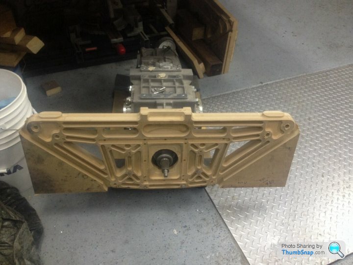
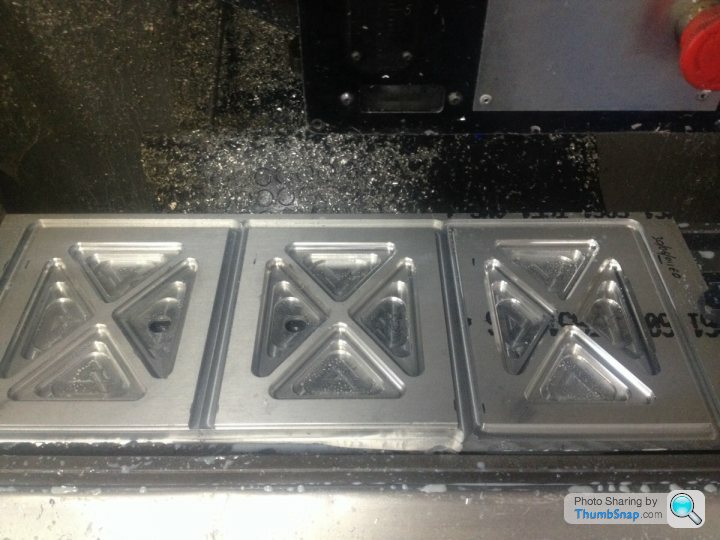
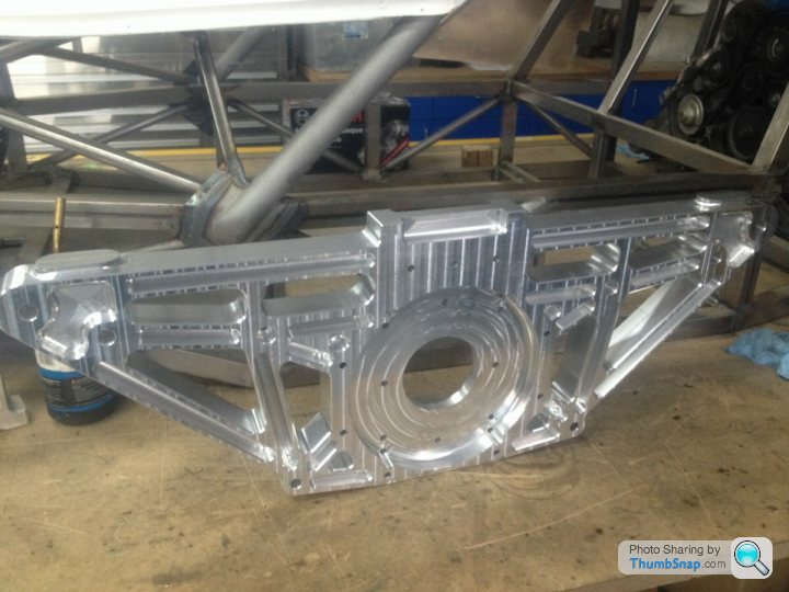
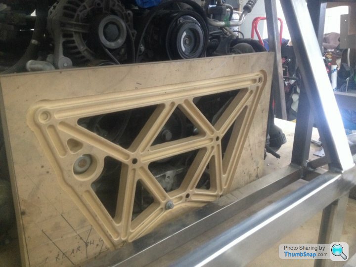
After confirming all my Cad works was OK and the engine is in the best position I can get it, I've started machining that expensive 2" thick Billet. But due to being 39" wide, and I only have a X axis machining window of 34" I've had to break up the machining into 4 operations. Op1 now complete..
Edited by GTRCLIVE on Saturday 10th January 00:42
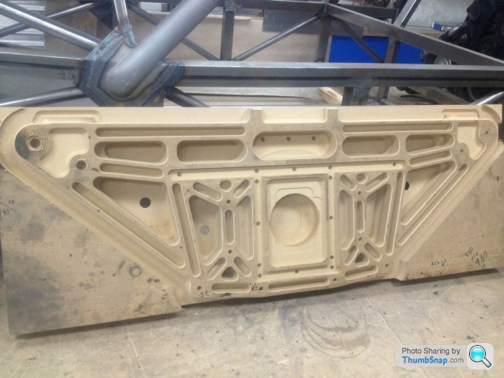
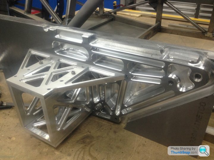
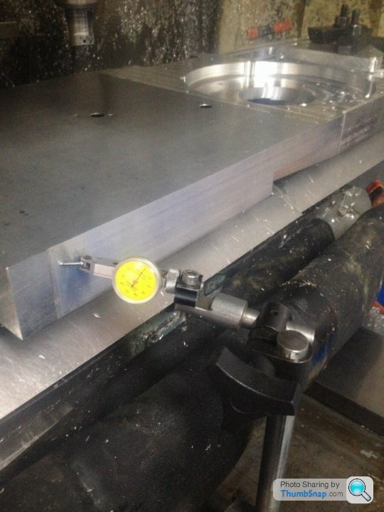
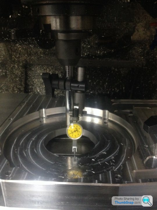
I machine a flat surface on the x axis ( left to right ) on the excess material around the part , that helps me keep it square
As i can clock that back in after moving it, with a DTI . Then the round bore for the crank / input shaft Center line is easy to dial back in with the DTI setup on a tool I put in the spindle . Just to make things easy I always have a bore on the part some where , and I always set that up as x & y zero point in my CAM software. That bore on this part isn't suppose to be a bore but a square whole, so at some point before I Anodize the part I'll drop it back on the mill and cut it out. Don't want all that excess weight now do we !!!
Square:-
Zero Point:-
Edited by GTRCLIVE on Wednesday 14th January 17:41
aww999 said:
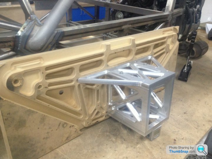
What is that big machined chunk for - a way of attaching the engine to the chassis/suspension? WIll the engine be taking suspension loads?
PS: This isn't leading onto me criticising your design or asking if you've considered XYZ, you have gone way outside my sphere of engineering knowledge so I'm genuinely curious!
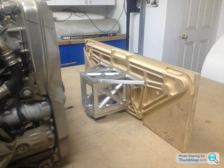
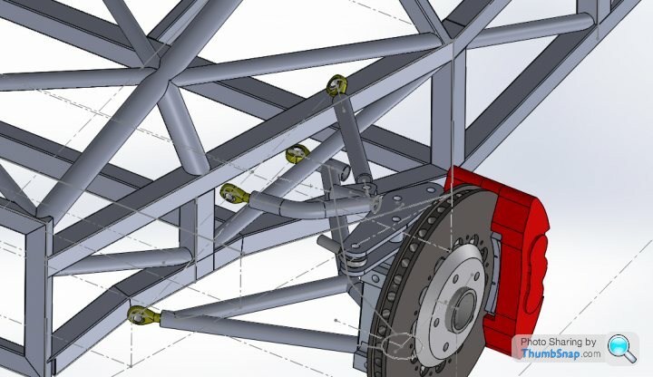
There's 6 bars that attach this plate to the chassis, so most of the Torsion loading is taken by them, but the engine will be stressed in a Vertical Plain load along the center line of the car. All will become clear soon once you see all the parts bolt together... PS: This isn't leading onto me criticising your design or asking if you've considered XYZ, you have gone way outside my sphere of engineering knowledge so I'm genuinely curious!
The machining of all the parts is going to take a big chunk of the time, but when done the making of the Suspension Wishbones wont be long at all. About a 8 hour day will be enough to build each corner of the suspension...
Classic Englishman in his shed, I must be... but I'm also a Mechanical Engineer who started life building CNC Machine tools for a living. This can be a bad thing as you tend to do everything yourself with the remit of "It cant be that hard"
  So I built my own shed, and of course it wasn't going to be any old ply wood covered B&Q flat pack....
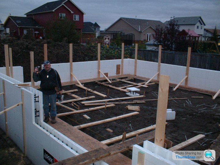
1100sqft roughly ICF 12" thick walls (well insulated but also and the main reason good sound proofing so I can work late and not disturb the locals) In floor heating, 5.1 surround sound, Over head project, In floor Scissor lift you get the idea... What I didn't spend on trades people I spent on the garage its self
This build is generating allot of interest for me and I'd love to turn it into a full time gig, but for now I have a day job and a understanding wife that lets me spend most of my spare time in my Man Cave/Shed....
I must be... but I'm also a Mechanical Engineer who started life building CNC Machine tools for a living. This can be a bad thing as you tend to do everything yourself with the remit of "It cant be that hard" So I built my own shed, and of course it wasn't going to be any old ply wood covered B&Q flat pack....1100sqft roughly ICF 12" thick walls (well insulated but also and the main reason good sound proofing so I can work late and not disturb the locals) In floor heating, 5.1 surround sound, Over head project, In floor Scissor lift you get the idea... What I didn't spend on trades people I spent on the garage its self
This build is generating allot of interest for me and I'd love to turn it into a full time gig, but for now I have a day job and a understanding wife that lets me spend most of my spare time in my Man Cave/Shed....
Id love to build a house with the stuff.... I doubled the footprint of the house by added another 1300sqft (yes I did build the wife a 200sqft Library when I built the garage) and the heating bill only went up about 25% .... Just well worth the extra cost....
Edited by GTRCLIVE on Sunday 25th January 07:12
zeb said:
clive.....I wish your were my neighbour !!
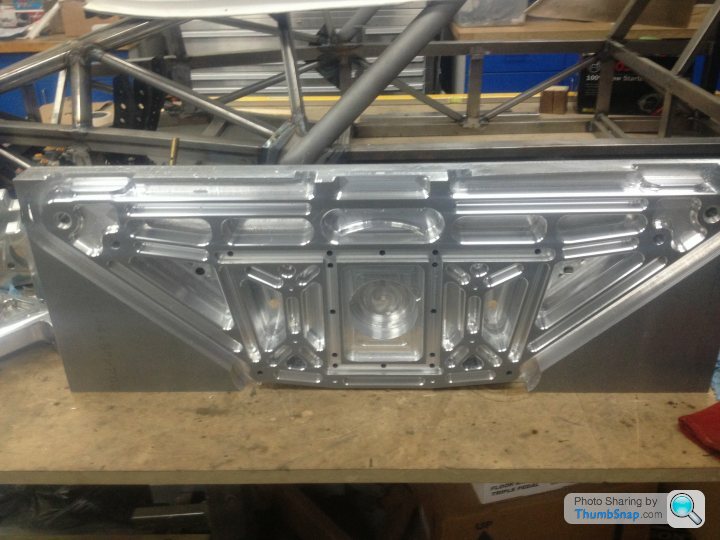
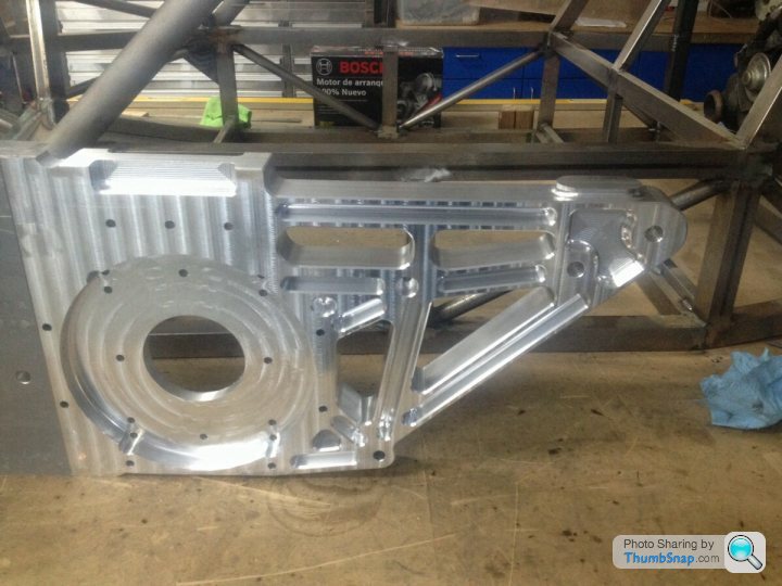
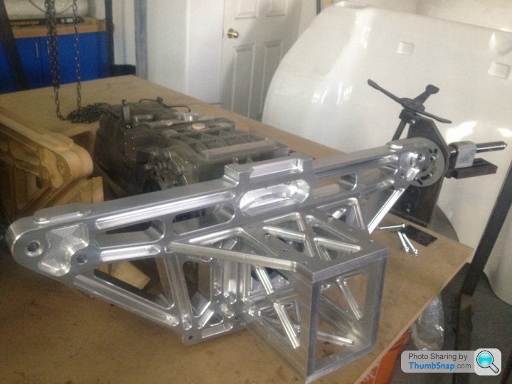
Plenty of room in Canada !!!Today's progress....
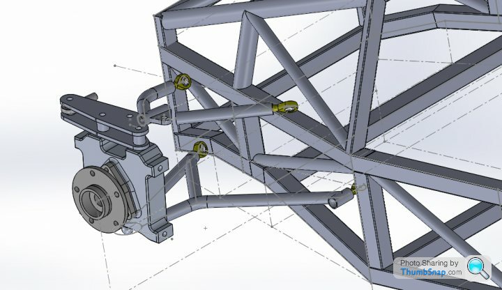
One half of the engine front plate done but while the millers been doing it thing I've been doing some Cad work on the front Wishbones.... still playing with clearances for + to - 35deg steering, shocks, steering rack etc brackets are easy once this parts done...
Edited by GTRCLIVE on Friday 23 January 05:22
There will be a Clevis on the top wishbone outer joint that with the Rod ends will make adjusting the Caster really easy. They had them on the original so it seemed a nice touch to keep. Lower WB rear joint needed to be placed far back into the chassis to get clearance for the floor and still make a nice straight line for the pickup points.
Gassing Station | Porsche General | Top of Page | What's New | My Stuff