Half the car is dead :-(
Discussion


Penelope Stopit said:
Purely out of interest
Are you sure the above is correct?
Should
Red/Yellow cable [B5 - Dip Power] to the Blue/Red cable [B4 - Dip Beam Drive] at the Dim Dip Control Unit ECU plug
Read
Red/Yellow cable [J43 A1 - Dip Power] to the Blue/Red cable [J43 A2 - Dip Beam Drive] at the Dim Dip Control Unit ECU plug
Yes I think you're right and to be honest unless we meter these diagrams out then it's going to be difficult to be 100% trusting in themAre you sure the above is correct?
Should
Red/Yellow cable [B5 - Dip Power] to the Blue/Red cable [B4 - Dip Beam Drive] at the Dim Dip Control Unit ECU plug
Read
Red/Yellow cable [J43 A1 - Dip Power] to the Blue/Red cable [J43 A2 - Dip Beam Drive] at the Dim Dip Control Unit ECU plug
I hadn't noticed the upside down numbering on the plug, so I think you are correct that the pin naming should be changed - here's the logic I used to get where I am
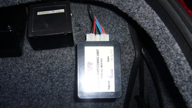
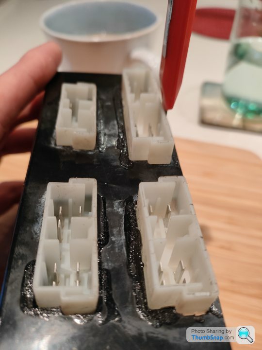
1. Photo of the unit
Starting on the top right you can see a Red/Yellow cable and a Blue/Red cable next to it - this matches the wiring diagram if you trace out the top wire back to the Lights ECU as per highlighted below
2. Wire trace
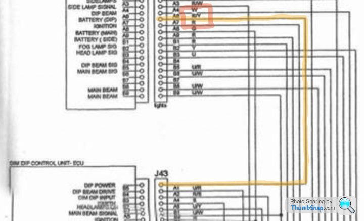
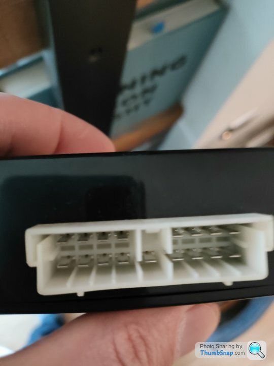
So if we go with the logic that the top left wire as you look at the back of the unit is A1 as per other plugs, then your logic makes sense
 --------------------
| A1 A2 |    | A4 A5 |
  B1 B2 | B3 | B4 B5
  ------------------
Also I think the labelling of the plug on J43 is wrong on both sides.
If you look at the other plugs, A1 is above the first wire as per this screenshot, whereas on J43 they have the second wire labelled as A1 which is incorrect. Also the A row is always used as the key with the middle wire having no pin (I have some of the control units here and have checked that) so A3 should be not populated
This would give us:
2.2 Dim Dip Control Unit - ECU (J43)
A1 - Dip Power (R/Y) [traced from 'Lights ECU']
A2 - Dip Beam Drive (U/R)
-
A4 - Dim Dip Input (R/B)
A5 - Earth (B)
B1 - Headlamps On (U/Y)
B2 - Main Beam Signal (U/W)
B3 - Ignition (R)
B4 - N/C
B5 - N/C
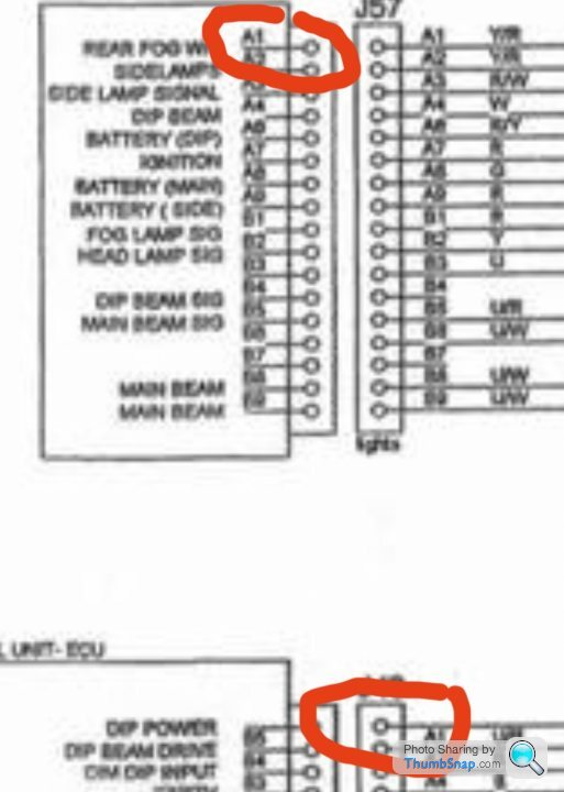
If you look at the other plugs, A1 is above the first wire as per this screenshot, whereas on J43 they have the second wire labelled as A1 which is incorrect. Also the A row is always used as the key with the middle wire having no pin (I have some of the control units here and have checked that) so A3 should be not populated
This would give us:
2.2 Dim Dip Control Unit - ECU (J43)
 --------------------
| A1 A2 |    | A4 A5 |
  B1 B2 | B3 | B4 B5
  ------------------
A1 - Dip Power (R/Y) [traced from 'Lights ECU']
A2 - Dip Beam Drive (U/R)
-
A4 - Dim Dip Input (R/B)
A5 - Earth (B)
B1 - Headlamps On (U/Y)
B2 - Main Beam Signal (U/W)
B3 - Ignition (R)
B4 - N/C
B5 - N/C
Noticed those errors and should have mentioned them earlier when posting a diagram that shows the correct plug aperture IDs
Good that you've been able to view and correct the errors
Did someone move a piece of paper while scanning it?
Fortunately have now been able to view many images of all the lighting ECU plugs
"Every picture tells a story" is definitely true with these circuits, every wire can be viewed and checked for correct IDs, cable sizes also are of much help in proving the diagrams to be correct or not and the different sizes are often easily seen in the images shown here or at Google
In looking for images, noticed that there are many topics about the lighting circuit
Some of the circuit has already been covered
Perhaps someone has already drawn and posted a modification like I'm about to
Anyway, It's been a pleasure working through the diagrams with you
Will post some more diagrams shortly
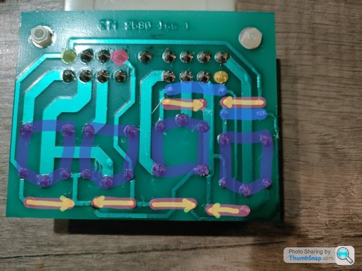
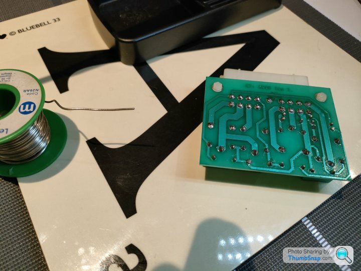
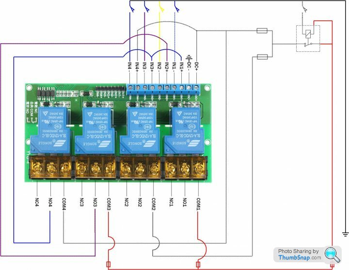
So the 12V diodes for fixing the Indicator & Hazard Lamps Switching Unit have arrived so I soldered that in place and documented the flow of the current that this makes on the PCB and thus the relays
The low current inputs are highlighted with dots below:
B1 - RH Turn Signal (G/W) (green)
B4 - LH Turn Signal (G/R) (pink)
A9 - Hazard Signal (N/B) (yellow)
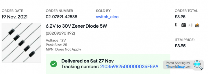
Diodes have arrived
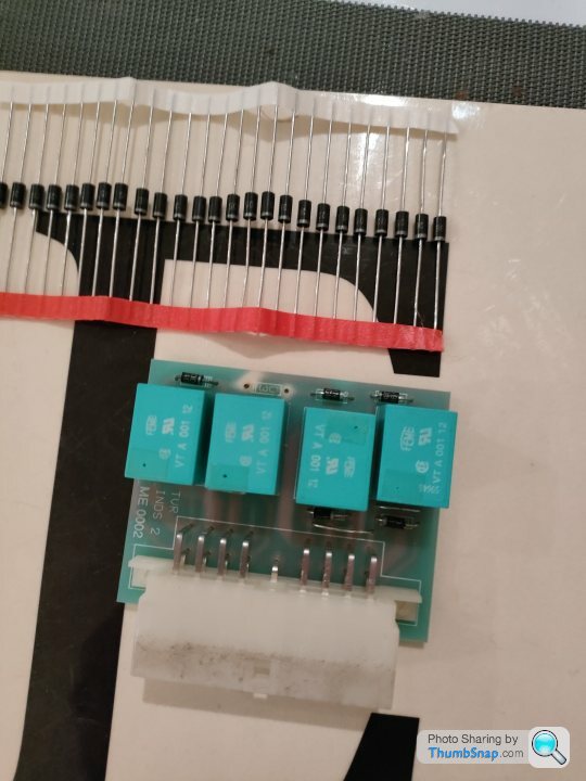
Soldered in place
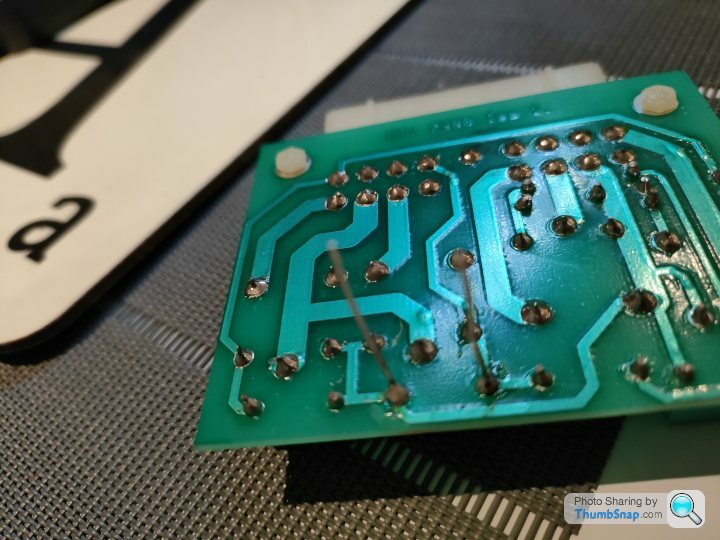
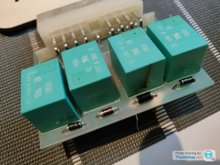
Continuity tested with a multimeter and extra legs trimmed - all tests fine on connections with junctions either side
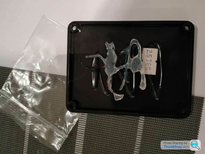
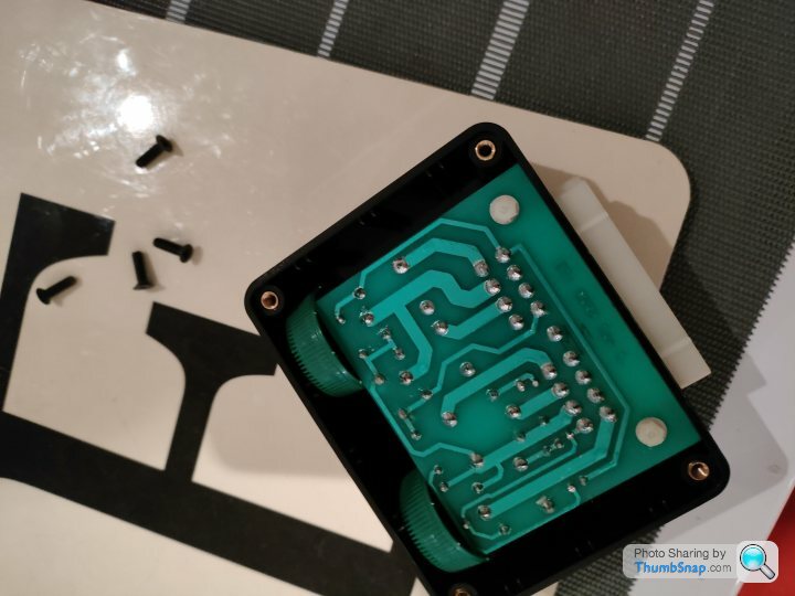
Last thing to fix is that the factory used liberal amounts of glue to hold the boards in place as they are smaller than the boxes they are in. It's pretty ugly and not something that I wanted to do, so my good old solution of 2 litre water bottle tops came to the rescue
The low current inputs are highlighted with dots below:
B1 - RH Turn Signal (G/W) (green)
B4 - LH Turn Signal (G/R) (pink)
A9 - Hazard Signal (N/B) (yellow)
Diodes have arrived
Soldered in place
Continuity tested with a multimeter and extra legs trimmed - all tests fine on connections with junctions either side
Last thing to fix is that the factory used liberal amounts of glue to hold the boards in place as they are smaller than the boxes they are in. It's pretty ugly and not something that I wanted to do, so my good old solution of 2 litre water bottle tops came to the rescue
Penelope Stopit said:
Anyway, It's been a pleasure working through the diagrams with you
Will post some more diagrams shortly
Thanks and yes it is very satisfying to work this through and bounce ideas backwards and forwards so definitely vice verse Will post some more diagrams shortly
I think when we have the working replacement circuit we should give it to some of the cerbera website guys to host, and maybe start a separate sticky thread so that it's available for everyone rather having to read through our explorations
Byker28i said:
And yes, a hot glue gun tends to be an essential tool when working on TVR electrics and control boxes 
Thanks I'm going to be looking at the Door / Window Control Box later on today which from an initial opening is a two layer board with some ribbon cable connecting the two boards together
Anyone ever worked on one of these before and are there common areas of the board where they go wrong that I should focus on?
I'm hoping it's another blown diode or similar from when the fusebox imploded and obviously by the electrical effect to the Indicator Box shorted itself somehow

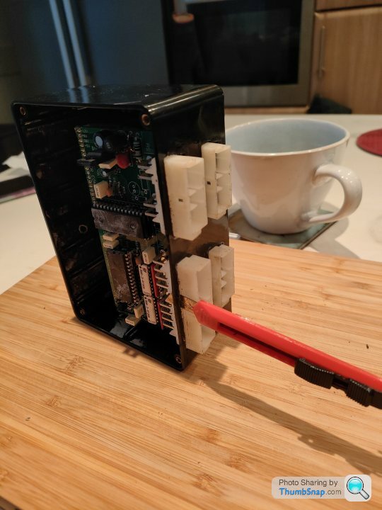
Door Control - ECU investigation: Day 1
So the lovely people at TVR saw not only to use a hot glue gun to hold the PCBs in place on Door Control - ECU (DC-ECU) but also liberal amounts of super glue but armed with a trusty flat craft knife, and some patience I managed to slowly separate the case from the connector by sliding the blade down between the two and voila I can now get to both layers of PCB to check them out
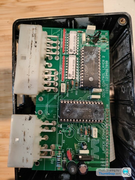
The top layer PCB contains all of the power conversion and logic chips to drive the doors and is primarily controlled by two programable PICs - one hand labelled "Door In" to handle the door closing, and the other "Door Out" to handle the door opening
There are a few other chips to smooth out the +12V power source and to provide the +5V power source needed by the TTL chips which are over near the TVR logo etched on the PCB
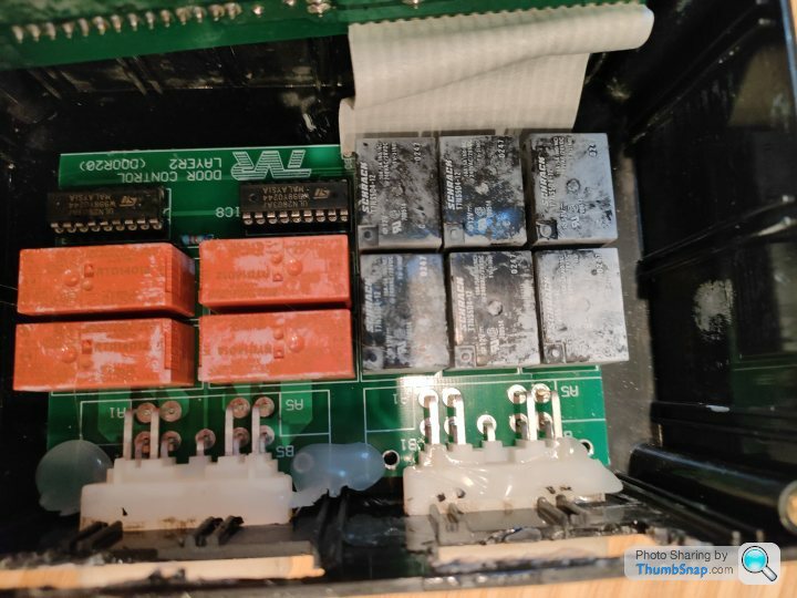
The lower board contains all of the micro relays needed to drive the doors such as for the window, lock etc. and would actually be very easy to design a replacement for as this is simple turned on and off by the PICs on the top as needed
So I went sniffing around the boards for two reasons - one to fundamentally try and document what is on each PCB so I / we all have it for reference and b. to see if I could spot any likely contenders that might be why my board has stopped working since the fusebox imploded
The ST L7805CP - positive voltage regulator IC - just above the TVR logo etched on the top PCB is a possible contender as these normally overheat and then the front panel blows off as they are not being heat sinked enough, but this one looked OK even though there is no external heat sink which would probably help (*probably not on long enough to be needed to be honest)
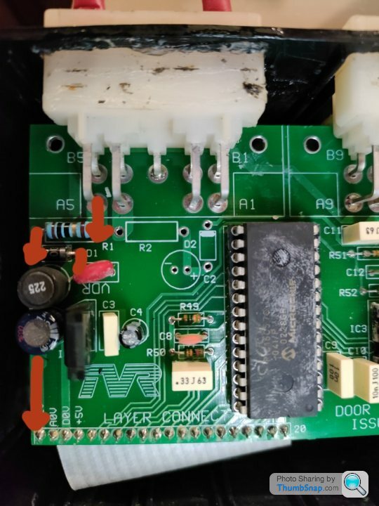
However.. sniffing around over by the +12V input there is a +12V diode very like the one on the Lights / Indicator control box that I replaced that would be a likely candidate to be blown if it got power sent the wrong way through it
Diodes should allow power through in one direction and not the other and show this when tested using a multimeter with a diode setting, and on mine this is showing 0.587 in one direction which sounds right, so I think the next best thing is to rig it up to the car and follow the +12V around the board to ensure that it's getting converted correctly to +5V for the TTL chips and that they are getting power correctly
Here's my list of components from my initial investigations with a brief explanation of what they do next to them (for those that are interested)
Door Control ECU
Lower PCB
6 x Schrack T7NS5D4-12 (0247) - Minature Power PCB Relay
4 x RTD14012 - Power PCB Relay
2 x ST ULN2803A / W998Y0244 - Eight Darlington Arrays
Ribbon Cable
1 - +12V
2 - A0V
3 - D0V
4 - +5V
5 - IC4 pin 18 [RC0]
6 - IC4 pin 19 [RC1]
7 - IC4 pin 20 [RC2]
8 - IC4 pin 21 [RC3]
9 - IC4 pin 22 [RC4]
10 - IC4 pin 23 [RC5]
11 - IC4 pin 24 [RC6]
12 - IC4 pin 25 [RC7]
13 - IC4 pin 27 [OSC1]
14 - IC4 pin 17 [RB7]
15 - IC4 pin 16 [RB6]
16 - IC4 pin 15 [RB5]
17 - IC4 pin 14 [RB4]
18 - IC4 pin 13 [RB3]
19 - IC4 pin 12 [RB2]
20 - IC4 pin 11 [RB1]
Upper PCB
2 x Microchip PIC16C57 0228GR - EPROM/ROM-Based 8-bit CMOS Microcontroller Series
2 x BI 898-3-R100K - Dual-In-Line Thick Film Resistor Networks
2 x Resistor Nets (red near A1 and A9)
1 x ST WI8134 L7805CP - positive voltage regulator IC
1 x 10ohm resistor (near A5)
1 x VDR (red circular device near A5) - voltage-dependent resistor
1 x 12V diode
So the lovely people at TVR saw not only to use a hot glue gun to hold the PCBs in place on Door Control - ECU (DC-ECU) but also liberal amounts of super glue but armed with a trusty flat craft knife, and some patience I managed to slowly separate the case from the connector by sliding the blade down between the two and voila I can now get to both layers of PCB to check them out
The top layer PCB contains all of the power conversion and logic chips to drive the doors and is primarily controlled by two programable PICs - one hand labelled "Door In" to handle the door closing, and the other "Door Out" to handle the door opening
There are a few other chips to smooth out the +12V power source and to provide the +5V power source needed by the TTL chips which are over near the TVR logo etched on the PCB
The lower board contains all of the micro relays needed to drive the doors such as for the window, lock etc. and would actually be very easy to design a replacement for as this is simple turned on and off by the PICs on the top as needed
So I went sniffing around the boards for two reasons - one to fundamentally try and document what is on each PCB so I / we all have it for reference and b. to see if I could spot any likely contenders that might be why my board has stopped working since the fusebox imploded
The ST L7805CP - positive voltage regulator IC - just above the TVR logo etched on the top PCB is a possible contender as these normally overheat and then the front panel blows off as they are not being heat sinked enough, but this one looked OK even though there is no external heat sink which would probably help (*probably not on long enough to be needed to be honest)
However.. sniffing around over by the +12V input there is a +12V diode very like the one on the Lights / Indicator control box that I replaced that would be a likely candidate to be blown if it got power sent the wrong way through it
Diodes should allow power through in one direction and not the other and show this when tested using a multimeter with a diode setting, and on mine this is showing 0.587 in one direction which sounds right, so I think the next best thing is to rig it up to the car and follow the +12V around the board to ensure that it's getting converted correctly to +5V for the TTL chips and that they are getting power correctly
Here's my list of components from my initial investigations with a brief explanation of what they do next to them (for those that are interested)
Door Control ECU
Lower PCB
6 x Schrack T7NS5D4-12 (0247) - Minature Power PCB Relay
4 x RTD14012 - Power PCB Relay
2 x ST ULN2803A / W998Y0244 - Eight Darlington Arrays
Ribbon Cable
1 - +12V
2 - A0V
3 - D0V
4 - +5V
5 - IC4 pin 18 [RC0]
6 - IC4 pin 19 [RC1]
7 - IC4 pin 20 [RC2]
8 - IC4 pin 21 [RC3]
9 - IC4 pin 22 [RC4]
10 - IC4 pin 23 [RC5]
11 - IC4 pin 24 [RC6]
12 - IC4 pin 25 [RC7]
13 - IC4 pin 27 [OSC1]
14 - IC4 pin 17 [RB7]
15 - IC4 pin 16 [RB6]
16 - IC4 pin 15 [RB5]
17 - IC4 pin 14 [RB4]
18 - IC4 pin 13 [RB3]
19 - IC4 pin 12 [RB2]
20 - IC4 pin 11 [RB1]
Upper PCB
2 x Microchip PIC16C57 0228GR - EPROM/ROM-Based 8-bit CMOS Microcontroller Series
2 x BI 898-3-R100K - Dual-In-Line Thick Film Resistor Networks
2 x Resistor Nets (red near A1 and A9)
1 x ST WI8134 L7805CP - positive voltage regulator IC
1 x 10ohm resistor (near A5)
1 x VDR (red circular device near A5) - voltage-dependent resistor
1 x 12V diode
Edited by Juddder on Sunday 5th December 19:48
From my side I wanted to test the power circuit of the Door / Window ECU so I grabbed a handy 12V switcher and rigged up some crimps to the main PCB power points (the two wire plug on the top circuit) and tested around
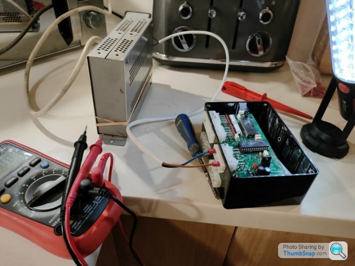
The good news is we are getting +12V flowing through the board correctly (+12V on the flow side of both the first resistor, and the diode) and +11.5V when it gets down to the second board ribbon connector so that should be correct to power the relays as needed
The +5V is good too so the TTL chips should be powering fine - I need to read up the datasheet on those and check which pins are Vdd (+5V) and Vss (GND) - actually just did that and it's pins Vdd = 2 and Vss = 4
Oh, and interestingly you can see that there are layouts for mirrored power circuitry on A4 too (*maybe as a backup or similar?)
Juddder, would you happen to know much about Optocouplers?
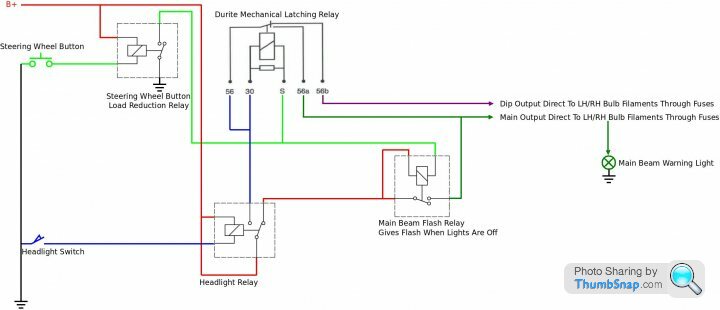
Was finishing off the below diagram a few days back and had to stop when realising that the module was rated at 12 volts when a TVR vehicles charging voltage could be 14.5 volts or more if a special upgrade had been undertaken
Surely the Optocoupler LEDs will fail due to over voltage or is there something I'm missing
TIA
This would be a simple and cheap Lights ECU replacement (if it worked)
Penelope Stopit said:
Surely the Optocoupler LEDs will fail due to over voltage or is there something I'm missing
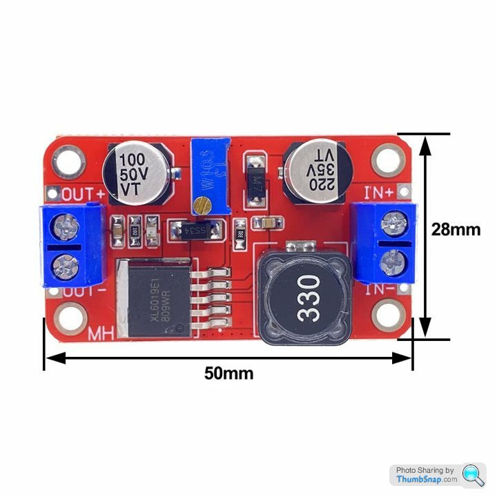
How about just putting a voltage regulator on the supply that will smooth out the +12V - +14V to provide a constant +12V whatever the state of the alternator / battery charge etc.?A cheapy buck/boost +12V regulator should do the trick and that would smooth out any fluctuations and prevent any harm to the optocouplers
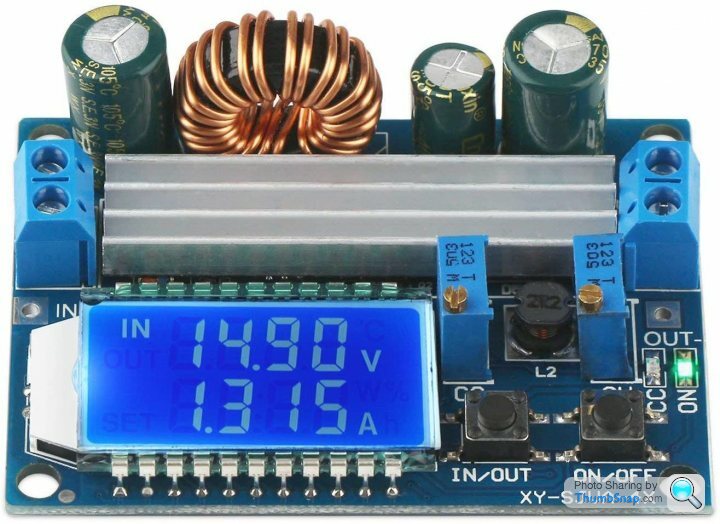
Something like this guy would potentially do the job or one could add a more snazzy one with LCD display of voltage, just for fun
Edited by Juddder on Friday 3rd December 12:46
Juddder said:
How about just putting a voltage regulator on the supply that will smooth out the +12V - +14V to provide a constant +12V whatever the state of the alternator / battery charge etc.?
A cheapy buck/boost +12V regulator should do the trick and that would smooth out any fluctuations and prevent any harm to the octocouplers
Something like this guy would potentially do the job or one could add a more snazzy one with LCD display of voltage, just for fun
This thread is magnificently detailed and dare I say geeky? Please keep going! A cheapy buck/boost +12V regulator should do the trick and that would smooth out any fluctuations and prevent any harm to the octocouplers
Something like this guy would potentially do the job or one could add a more snazzy one with LCD display of voltage, just for fun

Juddder said:
Penelope Stopit said:
Surely the Optocoupler LEDs will fail due to over voltage or is there something I'm missing
How about just putting a voltage regulator on the supply that will smooth out the +12V - +14V to provide a constant +12V whatever the state of the alternator / battery charge etc.?A cheapy buck/boost +12V regulator should do the trick and that would smooth out any fluctuations and prevent any harm to the optocouplers
Something like this guy would potentially do the job or one could add a more snazzy one with LCD display of voltage, just for fun
Good idea in regulating the supply voltage, the problem is that the switching from up front would also need regulating and all the work plus more components involved would turn a simple circuit into a not so simple circuit
Am getting closer to convincing myself that time was wasted due to not considering charging voltage before starting to draw the circuit
Wish there was more information/specification to be had about Optocouplers and input voltages
Gassing Station | Cerbera | Top of Page | What's New | My Stuff