Alarm wiring diagram?
Discussion


Does anyone have a copy of the Meta M99T installation guide or the TVR alarm wiring that shows which of the sensors go to which set of connectors on the alarm?
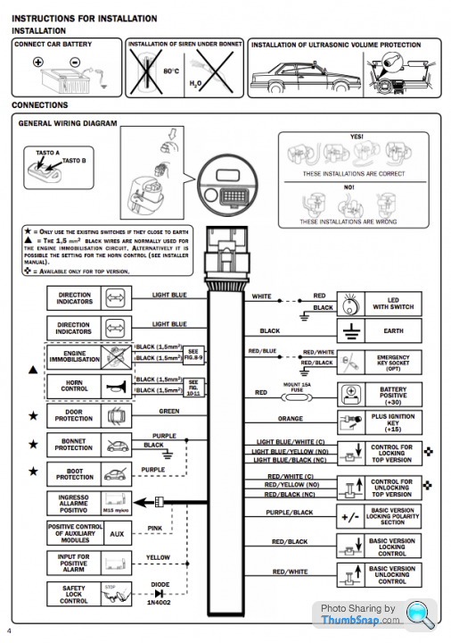
The TVR Main Harness wiring diagram shows the Bonnet Switch Sensor going to J30 (I can't think of anything but the alarm that would use this) but I can't seem to easily find the diagram showing J30 -> Alarm
I've searched the Abacus Alarms site, and Meta's and the nearest I can find so far is the Meta User Guide (handy but no wiring diagram) and the Meta M8700 Installers Manual (good but a different model of alarm)
http://www.metasystem.co.uk/index.php/msy_eng_en/c...
https://www.metasystem.it/index.php/content/downlo...
The reason I'm looking for it is my alarm enables and disables fine, but once it goes past the 25 second initial delay time (constant LED on) into alarm activated mode (LED flashing), the greenpanic button Door/Boot Lock Switch (see note below) on the middle of the lower centre console goes into rapid blinking (say once a second) while the red LED does it's expected every 3 or 4 seconds
Which leads me to believe that one of the sensors isn't closing / engaging correctly and this is the Meta's way of telling me that
Porsche alarms just give a little chirp from the horn if you enable the alarm and forget to shut the boot or bonnet - with TVR that would be too easy of course
[Additional] I checked in the Owners Manual and the Door/Boot Lock Switch is described as:
"Internally locks the doors (for personal security) and the boot lid. Illuminates when in operation. To exit the vehicle use the door release buttons in the armrests as normal."
So perhaps this is flashing because it can't successfully lock the doors or isn't getting the correct response from one of the doors, nor the alarm???
The TVR Main Harness wiring diagram shows the Bonnet Switch Sensor going to J30 (I can't think of anything but the alarm that would use this) but I can't seem to easily find the diagram showing J30 -> Alarm
I've searched the Abacus Alarms site, and Meta's and the nearest I can find so far is the Meta User Guide (handy but no wiring diagram) and the Meta M8700 Installers Manual (good but a different model of alarm)
http://www.metasystem.co.uk/index.php/msy_eng_en/c...
https://www.metasystem.it/index.php/content/downlo...
The reason I'm looking for it is my alarm enables and disables fine, but once it goes past the 25 second initial delay time (constant LED on) into alarm activated mode (LED flashing), the green
Which leads me to believe that one of the sensors isn't closing / engaging correctly and this is the Meta's way of telling me that
Porsche alarms just give a little chirp from the horn if you enable the alarm and forget to shut the boot or bonnet - with TVR that would be too easy of course
[Additional] I checked in the Owners Manual and the Door/Boot Lock Switch is described as:
"Internally locks the doors (for personal security) and the boot lid. Illuminates when in operation. To exit the vehicle use the door release buttons in the armrests as normal."
So perhaps this is flashing because it can't successfully lock the doors or isn't getting the correct response from one of the doors, nor the alarm???
Edited by Juddder on Sunday 30th July 17:15
Byker28i said:
For obvious reasons you wont find any wiring diagrams for it, the same reason all the wires to it are black.
Interestingly the M8700 installation manual (a later Meta alarm) has all of the wires labelled and colour coded so you know exactly what is going whereSo I've contact formed Meta Italy to ask them if they have the same for the M99T - will update if they do

Edited by Juddder on Friday 28th July 17:47
 Great stuff - many thanks for the offer and PM sent
fatjon said:
When you find out what the rapid green blink means please update us all. I have been asking everyone who will listen for 10 years and never got an answer. Mine will do it randomly while I'm driving and it also locks the windows shut when it goes into "blink mode"
Good to hear I'm not alone on this one and yes it is strange!MBE Italy were actually really helpful too and they mailed back the M99T2 Installation Instructions PDF which also has a coloured wiring table (perhaps not so useful if as everyone says the wiring on the Cerbera is all black!)
According to their wiring diagrams there is only one LED out, the white wire which on the Cerbera is connected to the lower dash red one, and this seems to be working fine
The green LED I am now thinking is therefore controlled by the Door ECU in the boot, which in turn is enabled / disabled by the Alarm
I've not disassembled the ECU PROM but put some feelers out with our ECU Insight group to see if anyone else has or knows of someone who has
My thinking is that if this unit does not get the correct feedback from the door actuators and window switches when it is enabled by the Alarm, then it goes into panic mode with the constant flashing
@FatJon - if yours is doing this while driving that would point towards a loose wire going to this unit, or something shorting on the loom at intermittent times
Any thoughts always welcome

tofts said:
Check the pink wire (on the door control unit), if this gets lifted from ground whilst car is unarmed the module will do odd things.
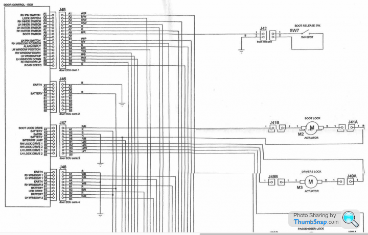
So on the wiring diagrams, Pink is colour 'K' and from the Rear Harness Part 1 diagram here that would be pin B3, J45 on the Door Control ECU which is labelled as 'Alarm Input'Any idea what this pin is meant to get fed from the Alarm?
Also, the only reference I can see on the Door Control ECU to LED (the green flashing LED on the centre console) is pin B3, J48 which is labelled 'LED DRIVE'
I'm wondering if the Door Control ECU not being connected completely means it starts sending panic signals to the LED DRIVE - of course would be nice if TVR had ever documented any of this!!
Gassing Station | Cerbera | Top of Page | What's New | My Stuff