A bit of progress, body off!!
Discussion


Finally had a bit of time to make some progress on the Cerb.
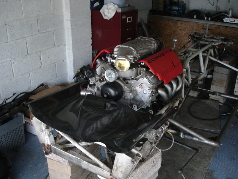
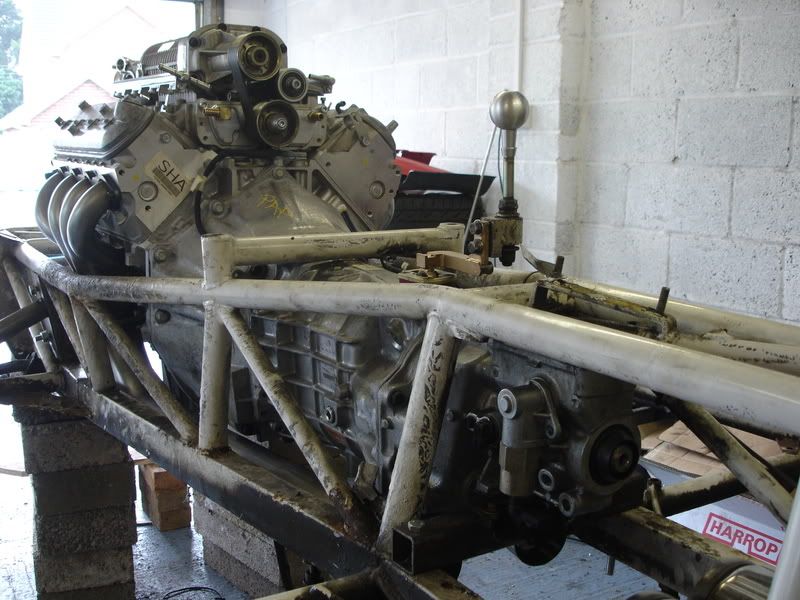
LS1 and T56 sitting in before body off. Note the A4 page with the pics of Brummies build for reference!
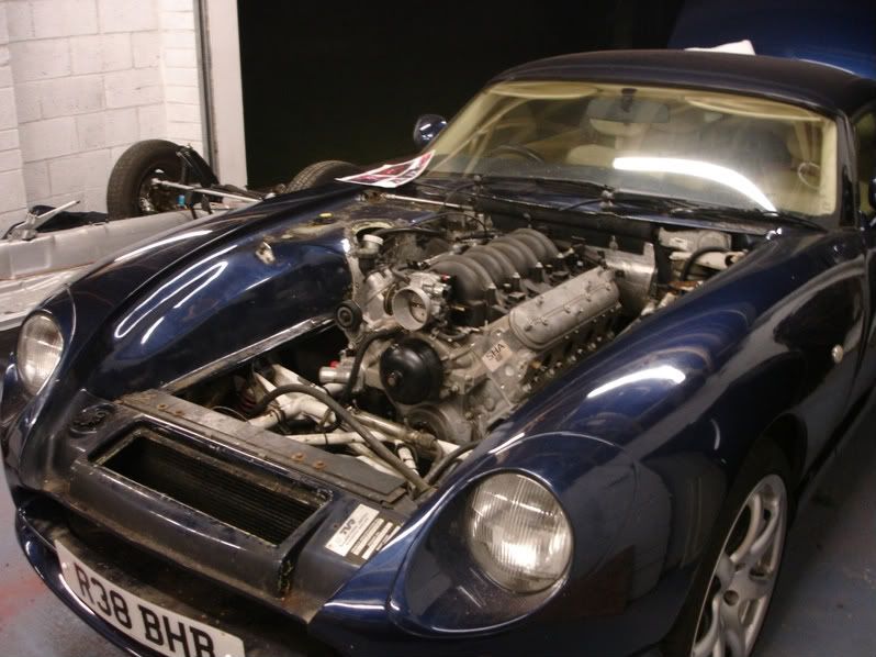
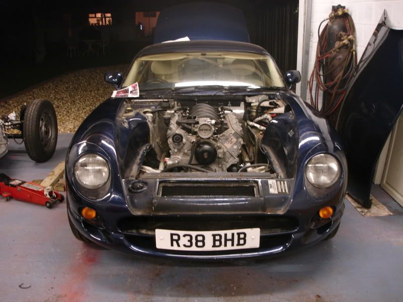
Lifted the body today with the help of 8 mates, its f'in heavy!! Worst bolts were the ones for seats, all needed to be cut off. All chassis nuts and bolts were fine, windy guns are a god send!!
You can see the engine mounts in the pics below. The vertical chassis tubes were removed and rectangle box section welded in place, just tacked for now. The engine mounts bolt to the box section.
T56 gearbox seems to fit OK, rear gearbox mount needs to be fab'd but no big deal. Got enough room for at least 2.5" exhausts. Bit tight in places but won't be more than an inch or so below the bottom chassis rail.
Looking into relocating the shifter location forward (same as a Viper). Potentially end up with a shift linkage thats visable in the cabin kinda link Spyker Spider style!!
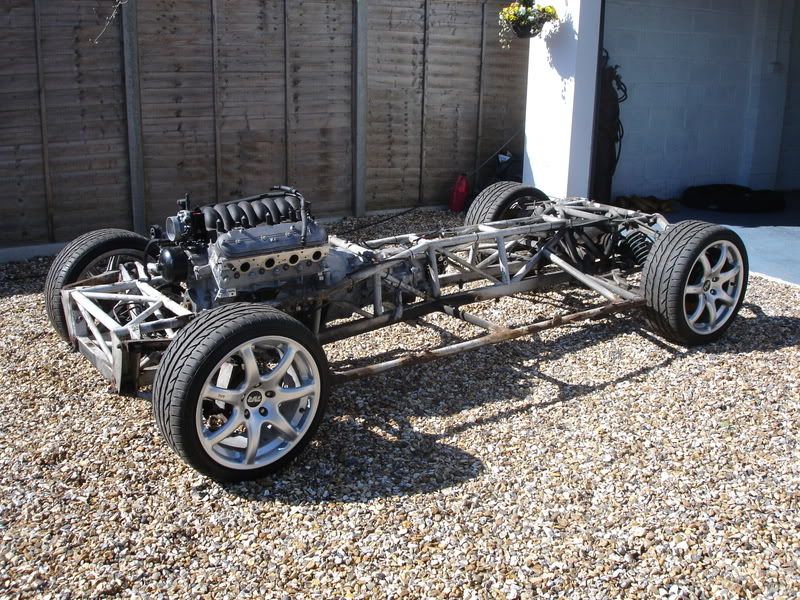
Chassis doesn't look too bad the outriggers are the worst but doesn't look like anything needs replacing.
Next job will be exhaust manifolds. Going for simple symetrical manifolds, they'll be short primaries (1 3/4 dia) but I don't think this will be a problem once the blower arrives!!
Well, after a week of fitting Koni/Eibach's to my Volvo, stripping down the beetle engine for the 356 replica and removing the Cerb body I'm knackered.
Day off tommorow me thinks.
Rich.
LS1 and T56 sitting in before body off. Note the A4 page with the pics of Brummies build for reference!
Lifted the body today with the help of 8 mates, its f'in heavy!! Worst bolts were the ones for seats, all needed to be cut off. All chassis nuts and bolts were fine, windy guns are a god send!!
You can see the engine mounts in the pics below. The vertical chassis tubes were removed and rectangle box section welded in place, just tacked for now. The engine mounts bolt to the box section.
T56 gearbox seems to fit OK, rear gearbox mount needs to be fab'd but no big deal. Got enough room for at least 2.5" exhausts. Bit tight in places but won't be more than an inch or so below the bottom chassis rail.
Looking into relocating the shifter location forward (same as a Viper). Potentially end up with a shift linkage thats visable in the cabin kinda link Spyker Spider style!!
Chassis doesn't look too bad the outriggers are the worst but doesn't look like anything needs replacing.
Next job will be exhaust manifolds. Going for simple symetrical manifolds, they'll be short primaries (1 3/4 dia) but I don't think this will be a problem once the blower arrives!!
Well, after a week of fitting Koni/Eibach's to my Volvo, stripping down the beetle engine for the 356 replica and removing the Cerb body I'm knackered.
Day off tommorow me thinks.
Rich.
Hi Guys, thanks for the comments all greatfully received.
Right, some answers. Firstly, Hi Mark good to hear from you, YHM, we're in all weekend be good to catch up with you and Claire.
Hi Don, would be interested in that shifter if it uses the forward inspection plate position, I'll send you a note. Cheers.
The engine is located as far back as I could possibly get it, the MAP sensor is about 10mm from the bulkhead. At the back of the gearbox is the tricky bit for the exhaust like you say.
Hears my plan.
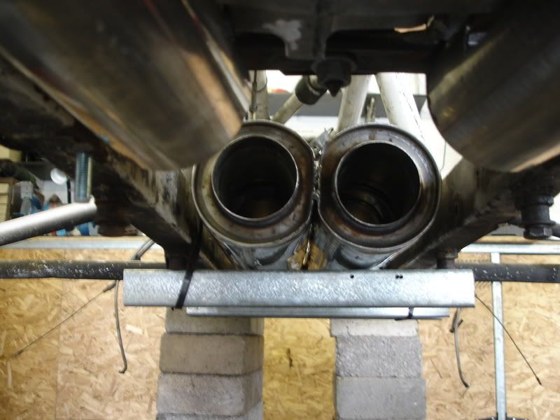
You can go 1 1/4" below the bottom chassis rail with no problems as thats the depth the chassis girdle runs at. That means at the tightest spot I've got a CSA of 2 1/4" by 10" to play with to get the exhaust through. This is where I'm planning to bring both exhausts together in a crossover pipe. I'm planning on using sheet metal to make the crossover up in box section.
With two 2.5" exhaust thats 10 square inches of CSA therefore thats 2" by 5" box section at the tightest point. I'll probably make it larger, even with twin 3" exhaust thats only 2" by 7" rectangle.
Will be challenging to fab it up, round tube to rectangle and all that but not impossible.
I'm not too worried about getting the exhaust theory spot on, I'm just looking at the exhaust as getting the gases away with minimal restriction.
It'll be boring getting things right first time!
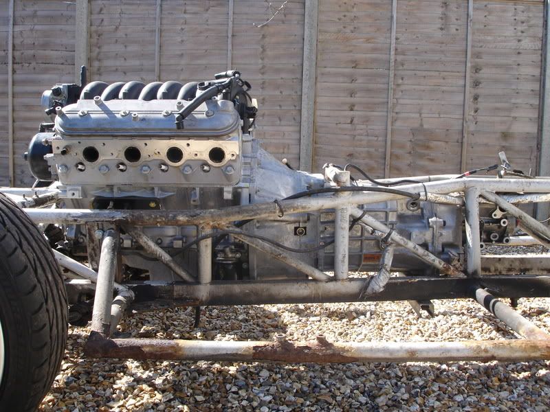
Hi Wins, Good to hear from you here a couple of pics of the mounts.
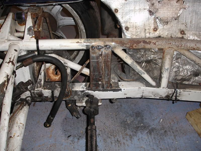
Please excuse the roughness they're just tacked in for now.
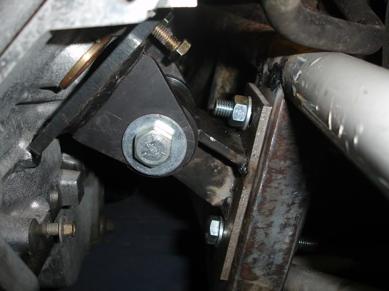
Ohh that reminds me, must do that bolt up.
You can see where the original mounts go, right at the front of the engine, so you'd have to have long mounts to get to those pickup points and I think you might foul where the auxilary drive belt goes.
Hi Richard, Taking the body off isn't too bad but I already had the AJP out of the way. Apart from undoing bolts, you have to disconnect the steering and brake lines at the pedal box, electrics for purge can, fuel pump and fuel lines. All seat belts need unbolting which requires lifting out the bottom of the rear seats. The door side front seat belt mounts need to have a small amount of glass fibre cut out from around them as they are glassed around after the body is fitted. You can see the upright seatbelt mount tags half way along the outriggers, its not much of a job.
Hi Bum, glad you're taking an interest, I think its good to come up with other idea's / solutions.
Been looking at outriggers again this morning, I recon welding in new ones will be quicker than cleaning these ones up. Cheers for the prompt.
Right heres the fun bit. I've always wanted to leave the engine alone and fit a blower. I was very tempted by the Vortech blower from A&A corvette in the states, and still am but I think a positive displacement blower would be more effective, larger area under the curve etc. So recently I'm looking at following the supercharged Monaro path. The Harrop M112 blower will fit under the bonnet with no mods. There not as effcient as vortech but I don't think power and torque are going to be lacking in any of these cars. We'll see I've got plenty of time to make a decision and also other things to sort out first.
Management wise I was looking at Emerald but lately I'm favouring using the ECU that came with my engine, the software you can buy for it looks very good and the ECu itself is very versitle, not many LS1 cars in the states run aftermarket management unless they're dragsters.
Cheers,
Rich.
Right, some answers. Firstly, Hi Mark good to hear from you, YHM, we're in all weekend be good to catch up with you and Claire.
Hi Don, would be interested in that shifter if it uses the forward inspection plate position, I'll send you a note. Cheers.
The engine is located as far back as I could possibly get it, the MAP sensor is about 10mm from the bulkhead. At the back of the gearbox is the tricky bit for the exhaust like you say.
Hears my plan.
You can go 1 1/4" below the bottom chassis rail with no problems as thats the depth the chassis girdle runs at. That means at the tightest spot I've got a CSA of 2 1/4" by 10" to play with to get the exhaust through. This is where I'm planning to bring both exhausts together in a crossover pipe. I'm planning on using sheet metal to make the crossover up in box section.
With two 2.5" exhaust thats 10 square inches of CSA therefore thats 2" by 5" box section at the tightest point. I'll probably make it larger, even with twin 3" exhaust thats only 2" by 7" rectangle.
Will be challenging to fab it up, round tube to rectangle and all that but not impossible.
I'm not too worried about getting the exhaust theory spot on, I'm just looking at the exhaust as getting the gases away with minimal restriction.
It'll be boring getting things right first time!
Hi Wins, Good to hear from you here a couple of pics of the mounts.
Please excuse the roughness they're just tacked in for now.
Ohh that reminds me, must do that bolt up.
You can see where the original mounts go, right at the front of the engine, so you'd have to have long mounts to get to those pickup points and I think you might foul where the auxilary drive belt goes.
Hi Richard, Taking the body off isn't too bad but I already had the AJP out of the way. Apart from undoing bolts, you have to disconnect the steering and brake lines at the pedal box, electrics for purge can, fuel pump and fuel lines. All seat belts need unbolting which requires lifting out the bottom of the rear seats. The door side front seat belt mounts need to have a small amount of glass fibre cut out from around them as they are glassed around after the body is fitted. You can see the upright seatbelt mount tags half way along the outriggers, its not much of a job.
Hi Bum, glad you're taking an interest, I think its good to come up with other idea's / solutions.
Been looking at outriggers again this morning, I recon welding in new ones will be quicker than cleaning these ones up. Cheers for the prompt.
Right heres the fun bit. I've always wanted to leave the engine alone and fit a blower. I was very tempted by the Vortech blower from A&A corvette in the states, and still am but I think a positive displacement blower would be more effective, larger area under the curve etc. So recently I'm looking at following the supercharged Monaro path. The Harrop M112 blower will fit under the bonnet with no mods. There not as effcient as vortech but I don't think power and torque are going to be lacking in any of these cars. We'll see I've got plenty of time to make a decision and also other things to sort out first.
Management wise I was looking at Emerald but lately I'm favouring using the ECU that came with my engine, the software you can buy for it looks very good and the ECu itself is very versitle, not many LS1 cars in the states run aftermarket management unless they're dragsters.
Cheers,
Rich.
eLSerbera said:
What he says about the ecu is true.
Basically all the GM ECUs used with their v8s (cars trucks etc) from 1999 to 2002 can be used for engine swaps where you need to keep cable throttle.
Rich there should be a GM part number on the ECU, if it is 12200411 then you have the best ecu to use, at least from what I have read.
Hi Rob,Basically all the GM ECUs used with their v8s (cars trucks etc) from 1999 to 2002 can be used for engine swaps where you need to keep cable throttle.
Rich there should be a GM part number on the ECU, if it is 12200411 then you have the best ecu to use, at least from what I have read.
My ECU is, Serv number is 09354896, HDW number 16220610. Any good? All I've found so far is its a 99-00 LS1 PCM, which is nice as the engine is from a 99 Camaro SS.
Wouldn't mind doing some reading up on it, have you got any good websites? Hopefully going to monkfish performance next week to look at a supercharger and have a chat about programming the ECU.
Rich.
Cheers Rob 
I've looked at a few of those websites but the rest look interesting.
Monkfish said it wouldn't be a problem writting to my ECU. They install supercharger kits on Monaros, so they've got a base map for me. I spoke to Roger there, very helpful.
Also, have a look at the Wortec website. I was speaking to Duncan last year at Goodwood from Wortec, he also said not a problem with the supercharger. Basically Monkfish install the Wortec supercharger kit which is built up from the Harrop M112 supercharger from Australia, theres a few guys on PH with this setup.
At the moment the plan is (this changes weekly BTW!) to use the monaro supercharger kit as close as possible so mapping etc is easier. Monkfish / Wortec use "HP tuners" ECU software. Apparently you can turn off the rear set of lambda sensors and the control of the air pump / emissions control.
Wiring loom wise Monkfish recommended http://www.painlessperformance.com/ for a basic wiring loom. Not sure I'll get one of these probably make my own up, I've got a copy of the pin out diagram for my ECU if you want it.
Rich.
Hi All,
Right here we go, been making good progress so heres an update.
Firstly, the supercharger is here
Its a roots type based on an Eaton design, produced by Harrop engineering in Australia to fit the LS1. It has a charge cooler system with a little water pump and cooling rad which I'll mount at the front of the car. The pulley allows 6psi, but can be changed to get 9psi and even 12psi but thats the limit for standard pistons. And before anyone asks it does fit under the bonnet, theres about 3/4 inch clearance at the tightest spot.
Supplied through Monkfish Performance, the dealer is Wortec, they're both PH regulars.
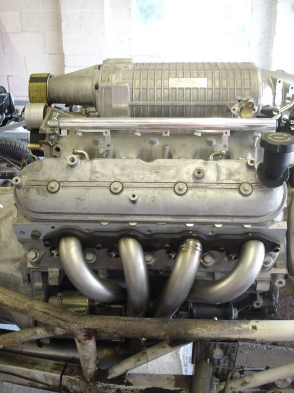
The biggest job has been the exhaust manifolds, I bought some 180 deg bends of 1 3/4 inch SS tube and a chop saw!!
A few weekends later including learning to TIG weld, I had made these. I found building manifolds a bit like doing a 3D jigsaw, but you can't try any of the bits first.
I know they're short and won't give much scaverging effect but I don't need to chase every last pony. Collector is 3". Being able to get to the sparkplugs was important . Clearance to the top chassis rail is about 1/2 inch at the closest bit, the engine mounts are pretty solid so fingers crossed.

During this time I was deciding how to overcome the problem of the gear shift. The T56 original position sits right where the handbrake goes so that was no good. Just by luck Don (Omerta) in New Zealand had one that fitted and was modified to bring the shifter up in the correct position for the Cerb. So he kindly shipped it over for me.
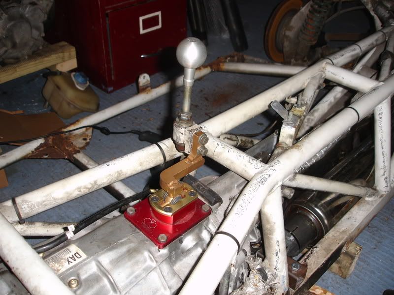
You can see above where I'm going to have to relieve the chassis a bit to give the gearbox some clearance under that top cross member but its nothing major. Theres a couple of other smaller places I'm going to relieve but thats more my own decision rather than having to. I rotated the reverse lock-out solenoid so it wouldn't foul the chassis, I thought I could ditch it but reverse is SO close to 5th its not worth chancing.
Just lately I've been repairing the chassis outriggers and started having a look at the exhaust. I'm running the twin 3" tubing under the T56 box, just a couple of small cut outs are needed to clear the rear of the box, as I've used 3" tubing I'm sure this isn't going to be too detrimental to exhaust flow.
I've got about 3/4 inch clearance between chassis and exhaust, which IIRC is about the same as the gap between the chassis and the original CATS. Ground cleance wise, the exhaust sits 30mm lower than the bottom chassis rail. This isn't a problem as the chassis girdle sits 25mm lower than the chassis rail so I'll make up some 5mm longer spacers.
Only pic I could manage I'm afraid, sun was coming directly into the garage.
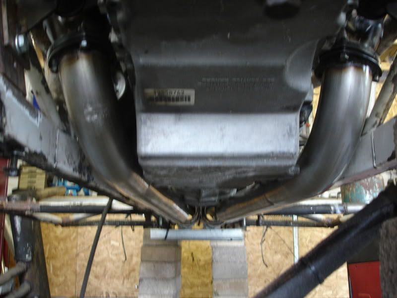
I'm going to fit the exhaust silencers underneath the prop shaft a bit like a Chimera exhaust. I bought two round 650mm long 3" bore silencers. I flattened a side on each and welded them together. Gives me about 1/2 inch cleance either side to the chassis rails. I'm going to rubber mount these to the chassis girdle, also like a Chim. This should stop them banging around. If its too noisey I can still fit extra silencers in the normal location.
Oh yeah, I've built the prop shaft as well, the TVR T5 gearbox uses the same output shaft as the T56 so all I had to do was shorten the original prop, just need to get it balanced now.
Apart from the Cerb, we've made good progress on my wife's Porsche 356 project and I've nearly finished CarbonAl's cerb's electrical gremlins, in return he's making me some carbonfibre engine panels modded to fit the LS1.
And if I ever need some enthusiasm I just watch these. Thats the supercharger whining
http://www.youtube.com/watch?v=mxS-mZuh-mE
http://www.youtube.com/watch?v=gW52JGR1db8
Rich.
Right here we go, been making good progress so heres an update.
Firstly, the supercharger is here
Its a roots type based on an Eaton design, produced by Harrop engineering in Australia to fit the LS1. It has a charge cooler system with a little water pump and cooling rad which I'll mount at the front of the car. The pulley allows 6psi, but can be changed to get 9psi and even 12psi but thats the limit for standard pistons. And before anyone asks it does fit under the bonnet, theres about 3/4 inch clearance at the tightest spot.
Supplied through Monkfish Performance, the dealer is Wortec, they're both PH regulars.
The biggest job has been the exhaust manifolds, I bought some 180 deg bends of 1 3/4 inch SS tube and a chop saw!!
A few weekends later including learning to TIG weld, I had made these. I found building manifolds a bit like doing a 3D jigsaw, but you can't try any of the bits first.
I know they're short and won't give much scaverging effect but I don't need to chase every last pony. Collector is 3". Being able to get to the sparkplugs was important
. Clearance to the top chassis rail is about 1/2 inch at the closest bit, the engine mounts are pretty solid so fingers crossed.During this time I was deciding how to overcome the problem of the gear shift. The T56 original position sits right where the handbrake goes so that was no good. Just by luck Don (Omerta) in New Zealand had one that fitted and was modified to bring the shifter up in the correct position for the Cerb. So he kindly shipped it over for me.
You can see above where I'm going to have to relieve the chassis a bit to give the gearbox some clearance under that top cross member but its nothing major. Theres a couple of other smaller places I'm going to relieve but thats more my own decision rather than having to. I rotated the reverse lock-out solenoid so it wouldn't foul the chassis, I thought I could ditch it but reverse is SO close to 5th its not worth chancing.
Just lately I've been repairing the chassis outriggers and started having a look at the exhaust. I'm running the twin 3" tubing under the T56 box, just a couple of small cut outs are needed to clear the rear of the box, as I've used 3" tubing I'm sure this isn't going to be too detrimental to exhaust flow.
I've got about 3/4 inch clearance between chassis and exhaust, which IIRC is about the same as the gap between the chassis and the original CATS. Ground cleance wise, the exhaust sits 30mm lower than the bottom chassis rail. This isn't a problem as the chassis girdle sits 25mm lower than the chassis rail so I'll make up some 5mm longer spacers.
Only pic I could manage I'm afraid, sun was coming directly into the garage.
I'm going to fit the exhaust silencers underneath the prop shaft a bit like a Chimera exhaust. I bought two round 650mm long 3" bore silencers. I flattened a side on each and welded them together. Gives me about 1/2 inch cleance either side to the chassis rails. I'm going to rubber mount these to the chassis girdle, also like a Chim. This should stop them banging around. If its too noisey I can still fit extra silencers in the normal location.
Oh yeah, I've built the prop shaft as well, the TVR T5 gearbox uses the same output shaft as the T56 so all I had to do was shorten the original prop, just need to get it balanced now.
Apart from the Cerb, we've made good progress on my wife's Porsche 356 project and I've nearly finished CarbonAl's cerb's electrical gremlins, in return he's making me some carbonfibre engine panels modded to fit the LS1.
And if I ever need some enthusiasm I just watch these. Thats the supercharger whining
http://www.youtube.com/watch?v=mxS-mZuh-mE
http://www.youtube.com/watch?v=gW52JGR1db8
Rich.
Brummmie said:
what kinda horses will this beastie make?
Hi Paul,Hopefully anything over 500bhp at the flywheel at 6psi. I believe the bench mark for a monaro, std heads cam and exhaust manifolds is 530bhp. 12psi puts it around the 600bhp mark and thats still std cam. I believe Monkfish saw 630bhp with a mild cam.
Outlook at the moment is to run it at 6psi sort everything out and maybe then go for 9psi, or maybe I'll stick a set of pistons and rods and cam in and go to 12psi. I really like how versitle this set up is, can't wait to fire it up.
Pulleys will be close, might have to do a bit of glass fibre work, but with CarbonAl on board its not a problem.
I recon the top engine cover will need modding thats why I'm having it build it carbon, would be good to see the pulley's from the drivers seat.

Rich.
Brummmie said:
So...does Carbon al want to make a centre outlet air box? cos i would like one too!
I had the same thought, but mine would need to be as original but with only one outlet. Alan said that wasn't a problem. I'll email him directly and get him to reply to this topic. I've nearly finished his car so hopefully he'll be in a good mood. I thought the air box was restrictive on these cars???? Maybe its just the air scoop underneath??
If it isn't, ACT sell replacement K&N panel filters that fit in the original position.
I was planning just a flat blanking panel with a hole in it which the induction tube would come through from a cone/oval filter in front of the radiator.
Any thoughts??
Rich.
JezF said:
Maximum respect, Rich. I'll be interested to see your beast in a couple of weeks time.
Jez
Yeah, I'll show you the TVR too. Jez

TVR is good but you can't get 10ft of drain pipe or 600kg of bricks in the back. Volvo's rule.

You might be able to see the Volvo autobox in some of the pics.
Rich.
The Ringmeister said:
diycerb said:
Brummmie said:
So...does Carbon al want to make a centre outlet air box? cos i would like one too!
I had the same thought, but mine would need to be as original but with only one outlet. Alan said that wasn't a problem. I'll email him directly and get him to reply to this topic. I've nearly finished his car so hopefully he'll be in a good mood. I thought the air box was restrictive on these cars???? Maybe its just the air scoop underneath??
If it isn't, ACT sell replacement K&N panel filters that fit in the original position.
I was planning just a flat blanking panel with a hole in it which the induction tube would come through from a cone/oval filter in front of the radiator.
Any thoughts??
Rich.
just a thought - could you use the air box lid from a speed 6 Cerb as this has one outlet?
Keep up the good work
Rich.
Brummmie said:
brogenville said:
Brummmie said:
I have cut the centre of the base out, a sort of bikini bottom shaped cut between the scoops, gives a bit more area to suck through.
Might not have been the best idea doing that, as you will have introduced some severe flow separation around your cut-out that could adversely affect the rest of the fluid flow coming into the intake. In fairness, you would need a back-to-back test to know what would be best, but I would have thought that the original design would probably have been better. All IMHO of course.I recon I'll go with my other idea, flat blanking plate instead of the air box housing with a hole in it for the induction pipe from a cone filter.
Al, hold off on the air box, splitter and light pods come first
. Kia said he'd do my top engine cover when I get the body back on. Your car should be finished by the end of the weekend, you're not going to recognise it.Rich.
Gassing Station | Cerbera | Top of Page | What's New | My Stuff