Who can make throttle shafts and install butterflies etc?
Discussion


Why do the people who made the castings not have the rest of the bits or is there more to the story than meets the eye? I could potentially point you in the right direction as I used to make TBs myself but as one offs it would be a very expensive exercise. Economies of scale is what makes these things viable. A little more info please.
Give these guys a shout. I'm sure it is something they can do.
http://www.autobionics.co.uk/index.html
Steve
http://www.autobionics.co.uk/index.html
Steve
Pumaracing said:
Why do the people who made the castings not have the rest of the bits or is there more to the story than meets the eye? I could potentially point you in the right direction as I used to make TBs myself but as one offs it would be a very expensive exercise. Economies of scale is what makes these things viable. A little more info please.
I presume because not everyone who casts items has a full machine shop to also machine themPumaracing said:
Why do the people who made the castings not have the rest of the bits or is there more to the story than meets the eye? I could potentially point you in the right direction as I used to make TBs myself but as one offs it would be a very expensive exercise. Economies of scale is what makes these things viable. A little more info please.
Because they're my own patterns and now they're cast I need a machinist to finish them off 
Boosted LS1 said:
Because they're my own patterns and now they're cast I need a machinist to finish them off
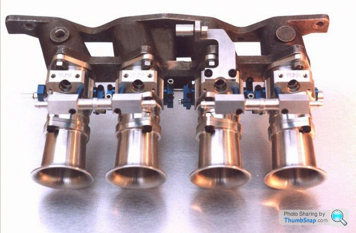
So are they singles that each need connecting with a linkage or doubles like DCOEs or what? Some pics would help. The main time consuming element is in the linkages. Boring to size and fitting butterflies is not usually a problem as long as it's a stock size butterfly. I hope you've considered and allowed for shaft bearings which can either be roller or bronze bushes if there's somewhere to fit them.Here they are Dave. Since the picture was taken they've been milled and have had the chokes bored but my toolmaker friend can't get access to the machinery he needs to finish them at present. He works at a car manufacturing plant and the machinery is in demand. I plan to use two 3/8 inch shafts per casting.

Looks like you don't intend them to ever break at least. Those manifold flanges must be 1cm thick!
Not sure how bearings are going to be fitted for the shafts as there's no machining access to both sides of each runner. All I can envisage is boring right through from each end and just pressing plain bronze bushes in and then reaming them to size. Tisn't easy boring in a dead straight line for that distance though so that both shafts end up meeting in the same place in the middle. I would suggest it would have been much better to cast just the manifold part as one unit with flanges for individual TBs to be bolted to. Then you could have just used off the shelf TBs in either singles or DCOE style from Jenvey or similar where someone has already done all the hard work designing linkages to suit.
I might even suggest it would be cheaper in the long run to hack the butterfly sections right off, TIG weld aluminium flanges on, machine those flat and drill them for stock TB bolt patterns. It's going to be a right mare trying to machine that lot up and design shafts and linkages.
I've spent many hundred hours dancing this dance when I was designing my own range of billet aluminium TBs in the 90s.
Have a think about what I've said before you go further. It might be worthwhile cutting through some of it over the phone rather than typing for hours.
Thanks for your advices Dave. The car plant has state of the art tooling to do the spindle boring, fit bearings. make the shafts etc. It's just he can't get onto it at the moment. I can buy off the shelf linkages from the US but it's really frustrating waiting to get the shafts fitted. Once he'd produced the first pair of tb's he was going to produce tooling to enable me to do a lot of the work 'at home'.
If your mate has the right facilities then I think it might be best to just wait for him. I can foresee an awful lot of problems when you actually get down to the nitty gritty of designing how everything is going to fit together and be located properly. I don't think either myself or my mate who did most of the machining on my own TBs would want to get sucked into something as complex as this as a one off. It could end up becoming a money pit.
Next time I'd really suggest again just make the manifolds to suit off the shelf TBs. No one else does it any other way.
Next time I'd really suggest again just make the manifolds to suit off the shelf TBs. No one else does it any other way.
Thanks Dave. These are downdrafts for a chevy v8 and a bit similar to a pair of kinslers. There isn't a lot of room on top for individual tb's. If I'd gone the crossover route individual tb's may have been a better bet Oh well, I'll have to wait a bit longer
BTW I liked your billet items, above.
Oh well, I'll have to wait a bit longer BTW I liked your billet items, above.
I'm sure you've already sunk a fair few quid into what you've had done so far but before you go any further you really need to design and draw out in detail every other part of the system and work out whether this can actually be machined in the real world. Spindles, bearings or bushes, seals to stop air getting in past worn bushes, how to connect the spindles and balance them both within one unit and to link the two banks, injector mounts, fuel rails and how to attach those, somewhere to mount a throttle pot.
I think when you get into that properly and in full detail you'll find that so many problems crop up it might never get off the ground. We spent months making prototypes, finding problems, redesigning and still in the end the linkages ended up too complex and expensive to make for my liking. It did all work very well and customers loved them but ideally they should have cost about 2/3 of what they actually did cost to make to earn really good money from it.
I just see no way of easily fitting bushes and seals and spindle locating mounts to any of the inner runners when there's no access to drill and tap or machine recesses to press things into. Also it only takes one of any of the dozens of necessary machining ops to go wrong and that's an entire bank scrapped. I wouldn't want to be the one trying to quote for machining something like that with the responsibility for paying compensation if a single op went tits up. In fact I'd exclude it in the contract or not get involved.
The devil is in the details I'm afraid and I see far too many details that haven't been thought out in advance. I don't want to rain on your parade but if it were me, and I have been through this so very many times, I'd bite the bullet now and weld flanges on for TBs that someone else has already designed. Or just alter the casting moulds to allow for separate TBs and start again.
Pumaracing said:
I'm sure you've already sunk a fair few quid into what you've had done so far but before you go any further you really need to design and draw out in detail every other part of the system and work out whether this can actually be machined in the real world. Spindles, bearings or bushes, seals to stop air getting in past worn bushes, how to connect the spindles and balance them both within one unit and to link the two banks, injector mounts, fuel rails and how to attach those, somewhere to mount a throttle pot.
My inspiration came from these and I've done casting modifications of my own to allow a bit more versatility. They'll work Dave. The above comments have already been thought out. I just got let down on the drilling, bugger 
Pumaracing said:
What sort of spindle bearings do those plastic ones have, how are they located in the castings and how do you intend to duplicate that in yours?
Those aren't plastic Dave, they're alloy, probably magnesium. They're painted black. We'll use a needle roller or a plain bearing.Ok, I've had a couple of thoughts. Bearings this small and short usually need to be pressed in against a stop to ensure they don't move and work their way into the bores and foul the butterflies. There's no easy way I can see of machining a recess with a bottom lip on the inner faces of the runners but if you made bronze top hat bushes with a small flange they could press in against the outer wall of each runner which would then at least prevent them moving inwards.
As for the drilling, if it's possible to use a line boring machine on holes this small, i.e. how camshaft and main bearing saddles are bored, then that would at least ensure that both spindles would align in the centre perfectly and be easily connected.
Anyway let us know how you get on when it's done.
Gassing Station | Engines & Drivetrain | Top of Page | What's New | My Stuff