S into 9 does go........
Discussion


So during a wonderful mid summer weekend of glorious UK weather, I decided to do some playing on the car rather than driving it.
I was not really impressed with the roll characteristics of my DB9 Volante, and a quick investigation proved why. No rear roll bar fitted! The last car I saw without a roll bar was a Mk4 Escort, and even Ford ended up fitting them after the first year due to the awful lean on the cars.
I then decided to install a Sport DBS roll bar kit and wondered whether it was a strightforward install.
So here is the results................
New 29mm rear bar, drop-links, bushes and clamps on the rear.
[pic]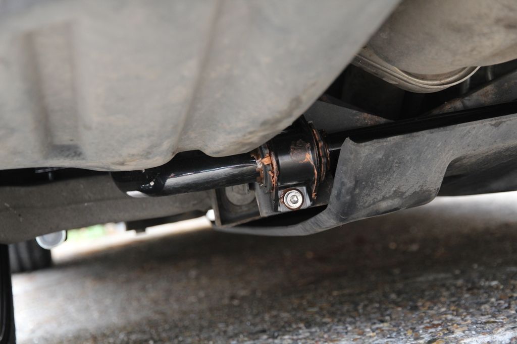 [/pic]
and a new front bar up from 26mm to 28mm reusing all the original links but with appropriate 28mm bushes...........
[pic]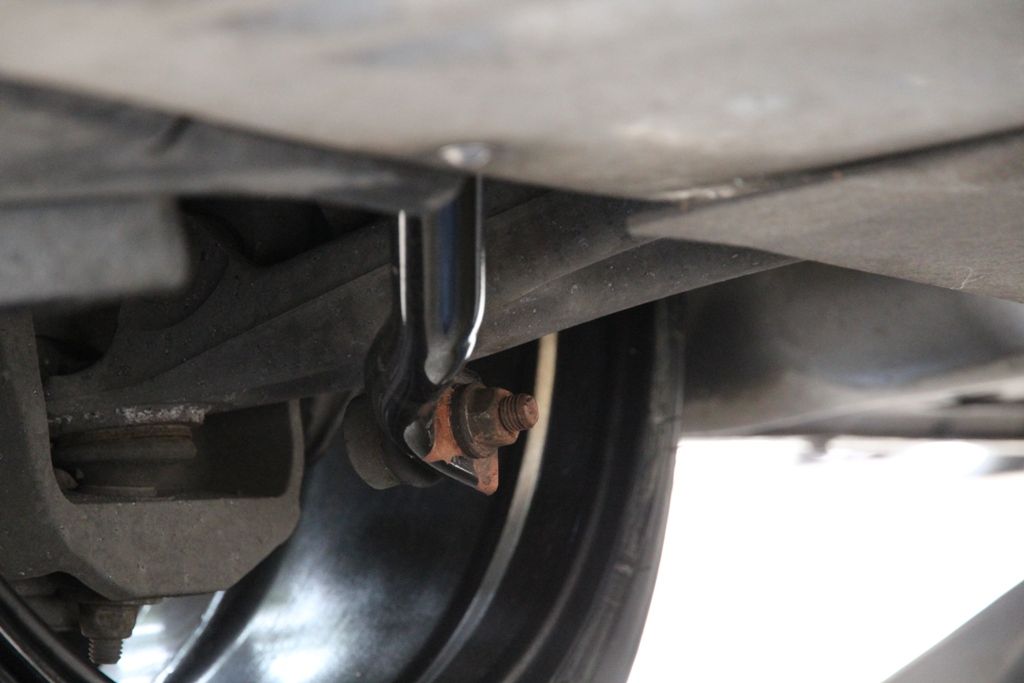 [/pic]
Well, the handling is transformed with absolutely no degradation in ride quality or comfort.
Time taken? A total of 2 hours taking my time copper-slipping bushes, bolt threads etc, torqueing everything in sight and cleaning up all the bits pulled-off before refitting them. Could easily be done in half that time if not being anal about the cleaning part.
So I then decided to continue playing with the car.
Watch this space fellow modifiers.
8Tech.
I was not really impressed with the roll characteristics of my DB9 Volante, and a quick investigation proved why. No rear roll bar fitted! The last car I saw without a roll bar was a Mk4 Escort, and even Ford ended up fitting them after the first year due to the awful lean on the cars.
I then decided to install a Sport DBS roll bar kit and wondered whether it was a strightforward install.
So here is the results................
New 29mm rear bar, drop-links, bushes and clamps on the rear.
[pic]
 [/pic]
and a new front bar up from 26mm to 28mm reusing all the original links but with appropriate 28mm bushes...........
[pic]
 [/pic]
Well, the handling is transformed with absolutely no degradation in ride quality or comfort.
Time taken? A total of 2 hours taking my time copper-slipping bushes, bolt threads etc, torqueing everything in sight and cleaning up all the bits pulled-off before refitting them. Could easily be done in half that time if not being anal about the cleaning part.
So I then decided to continue playing with the car.
Watch this space fellow modifiers.
8Tech.
Edited by 8Tech on Sunday 23 June 21:24
Edited by 8Tech on Sunday 23 June 21:25
SydneySE said:
Hi Mate,
Was this a straight bolt on job? no welding brackets to fit the rear drop links or drilling holes to mount the c-clamps?
Also, are these just the straight DBS parts if I order from scuderia parts?
Yes, all straight bolt-on.Was this a straight bolt on job? no welding brackets to fit the rear drop links or drilling holes to mount the c-clamps?
Also, are these just the straight DBS parts if I order from scuderia parts?
You will need, both bars, 2 sets of DBS roll bar bushes to suit, rear droplinks with 2 new hardened washers and rear "U" clamps. It actually takes longer removing the undertray at the front, cleaning it and refitting it than it does to fit the bars.
Cockernee said:
Nice work Gerry, good to see an experienced engineer looking at solutions and sharing with other owners.
How has the handling changed? Any noticeable under or oversteer or just reduced roll?
I have noticed significantly reduced roll but admit to never pushing it far enough to induce under/oversteer yet.How has the handling changed? Any noticeable under or oversteer or just reduced roll?
Given the correct conditions, and plenty of room, I will push harder and harder until one or the other raises its ugly head, or, confirm perfect balance as I hope.
I am now working with 2 of the worlds largest suspension manufacturers to produce springs and damper upgrades. Visiting the design and development sections this Friday actually to start on the designs.
yeti said:
I also have the front and rear shear panels from the Virage Volante installed on mine plus all the required anchor points retro-fitted and welded to my chassis - it was either that or buy a Virage rear end, no need for that if you know where and how to fit them. There are a lot of them, the chassis evolution continues very gradually but noticably year by year.
Makes a huge difference, you're right about that
I am looking at the shear plates but working through the components on the suspension one function at a time. As you very correctly say, with doing all at once, there is no way to know which component had what effect.Makes a huge difference, you're right about that
Well Friday was a big success with some perfect results from some very expensive and accurate hardware.
The first point of call was to find out what springs were installed on the DB9 Coupe. I used this as a starting point because that was where Aston based their rates for the Sport Pack springs. We know these were then uprated 63% and 68% for front and rear and extensive testing showed this to be a little too harsh.
However, 63%/68% of what? That was what I needed to find out.
So, removing a set of springs from a DB9 Coupe, I set about finding just what we were starting with.
The equipment used was an IST (Institute of Spring Technology) LT4-30000-3.
http://www.ist.org.uk/spring-load-testers-LT4.php
[pic]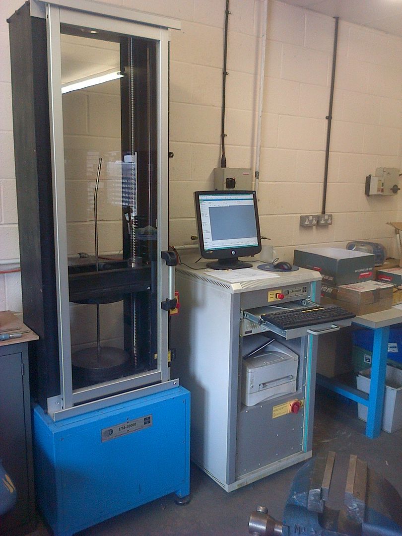 [/pic]
I loaded the springs into the computer controlled machine, rod through the middle of the spring is for safety, and the testing was fully automated from there. The spring is compressed to coil bind, and then unloaded until there is no load but the spring is in contact. This gives the machine the range of movement which it then divides into 100 to give a reading of load every 1% of the springs travel.
[poc]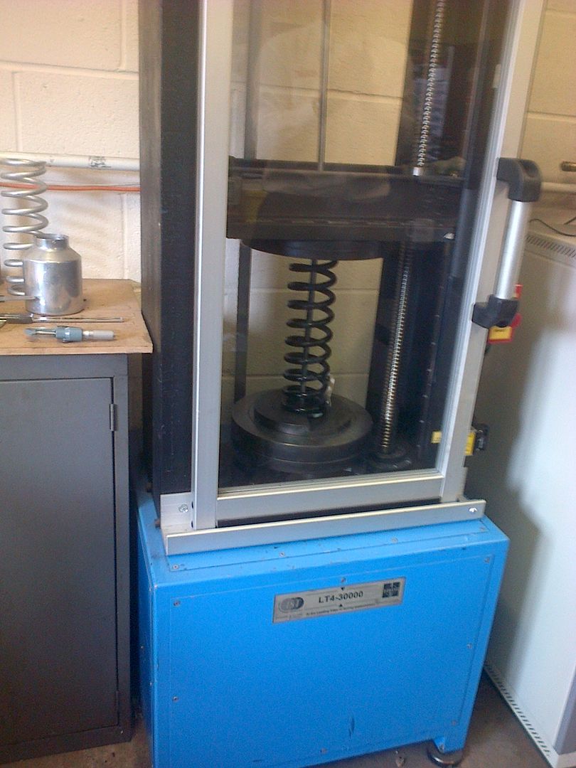 [/pic]
The machine then automatically compresses the spring again to coil bind, measuring the load every 1% of travel and then plots a graph of load against reflection.
We can then see both the spring rate at any point plus whether the spring is linear or progressive.
Below are the plots I got from the springs...........
FRONT.......
[pic]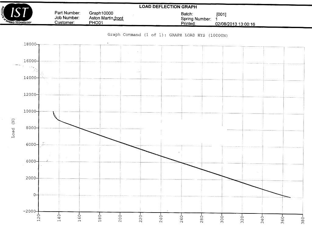 [/pic]
REAR.......
[pic]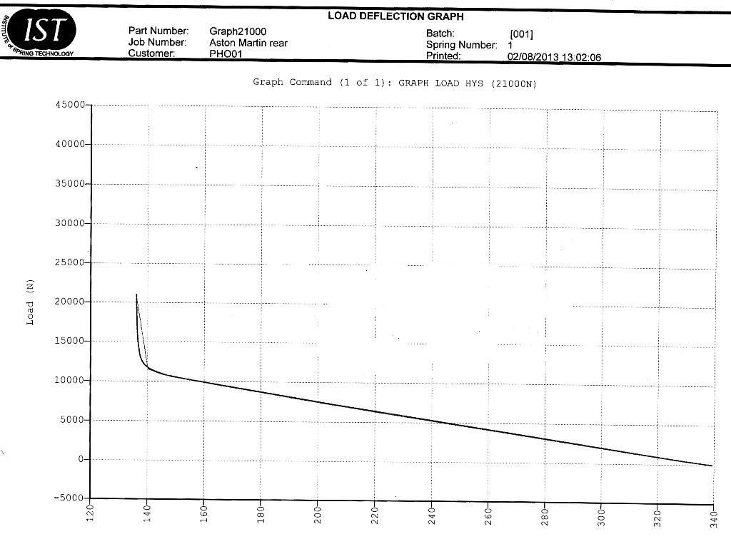 [/pic]
Both of these graphs show a very soft spring rate and I suspect this is designed for maximum comfort rather than performance and would explain partly the need for such large roll bars to control the body as there will be little help from the springs.
As I will be uprating the springs, it follows that the damper rates will also need to be uprated by a similar amount so I will be using some coilover tubes, seen here on the left against the stock DB9 shock on the right, and building bespoke dampers that will also be adjustable for ride height. Very, very similar to the race shocks from the N24 Vantage Race car.
[pic]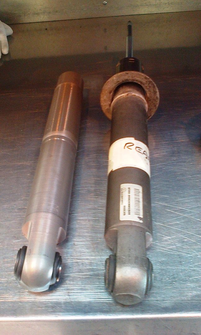 [/pic]
Units will be built in around 2 -3 weeks and then after installation, I can start fine tuning from my calculated settings.
Stay "Tuned".
The first point of call was to find out what springs were installed on the DB9 Coupe. I used this as a starting point because that was where Aston based their rates for the Sport Pack springs. We know these were then uprated 63% and 68% for front and rear and extensive testing showed this to be a little too harsh.
However, 63%/68% of what? That was what I needed to find out.
So, removing a set of springs from a DB9 Coupe, I set about finding just what we were starting with.
The equipment used was an IST (Institute of Spring Technology) LT4-30000-3.
http://www.ist.org.uk/spring-load-testers-LT4.php
[pic]
 [/pic]
I loaded the springs into the computer controlled machine, rod through the middle of the spring is for safety, and the testing was fully automated from there. The spring is compressed to coil bind, and then unloaded until there is no load but the spring is in contact. This gives the machine the range of movement which it then divides into 100 to give a reading of load every 1% of the springs travel.
[poc]
 [/pic]
The machine then automatically compresses the spring again to coil bind, measuring the load every 1% of travel and then plots a graph of load against reflection.
We can then see both the spring rate at any point plus whether the spring is linear or progressive.
Below are the plots I got from the springs...........
FRONT.......
[pic]
 [/pic]
REAR.......
[pic]
 [/pic]
Both of these graphs show a very soft spring rate and I suspect this is designed for maximum comfort rather than performance and would explain partly the need for such large roll bars to control the body as there will be little help from the springs.
As I will be uprating the springs, it follows that the damper rates will also need to be uprated by a similar amount so I will be using some coilover tubes, seen here on the left against the stock DB9 shock on the right, and building bespoke dampers that will also be adjustable for ride height. Very, very similar to the race shocks from the N24 Vantage Race car.
[pic]
 [/pic]
Units will be built in around 2 -3 weeks and then after installation, I can start fine tuning from my calculated settings.
Stay "Tuned".
Edited by 8Tech on Sunday 4th August 18:16
yeti said:
What are you trying to do?
There are several routes that have already been taken with great success; from the basics of replacing the springs with H&Rs lowering ones to the full magnetorheological damper (and spring) set up that I and a good few others have.
You may not have to reinvent the wheel here
H&R's are double the price they should be, they are really not THAT good.There are several routes that have already been taken with great success; from the basics of replacing the springs with H&Rs lowering ones to the full magnetorheological damper (and spring) set up that I and a good few others have.
You may not have to reinvent the wheel here
I will need to Google your "magnetorheological damper (and spring) set up", because if its the same as the BMW system, then reliability and again cost are really not that attractive.
I am looking for a driver tunable system, bespoke for the function the driver wants from his car.
Hello Sydney,
Firstly, thanks for showing some interest in the project. You are clearly looking along the same lines as I did originally, so to hopefully assist you in making your own decision, I can save you some time and effort with the following info.
Here we have a stripped standard front strut, the stock lower seat collar and a 2.25" ID spring sleeve similar to that you indicated from Summit.
[pic]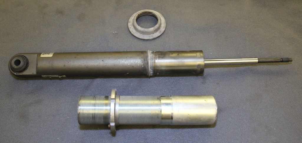 [/pic]
The sleeve for the 2.25" ID spring has an ID of 50.6mm so that it will sleeve over a 2.0" strut body. However, the strut has an OD of 51.66 mm and this is far too much for an interfearance fit. The sleeve is designed to either weld to the strut body or use the spring preload to hold it in position on an internal step at the top of the sleeve.
The strut body then tapers out to 54mm below the original spring seat that is held in position on the taper and a circlip as shown on the pic. FYI, the circlip is 116 mm down the strut body.
My best design, which I decided not to proceed with, was a sleeve made with the internal profile to match the external profile of the original strut body, with a press fit interfearance. The external thread could then be cut into that sleeve. This will also be the lightest option and would reinforce the strut tube.
The reason I never moved forward with this was that I wanted to have adjustable damping and the design really only gave ride height and spring rate options. feel free to go with that design though.
Your other issue is the top mount, if being reused...............
[pic]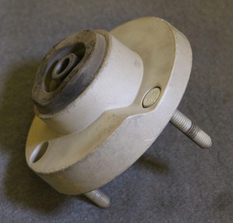 [/pic]
has a sloped/stepped seat because the OEM spring is flat ground at the bottom and stepped at the top. Almost all aftermarket racing springs are ground flat both ends. (the rubber seat from the top mount is not shown but is stepped the same).
It is easy enough to machine the top mount flat without losing any strength, but you cannot install a 2.25" spring on these struts, you need to go to a 2.5" spring. This gives you the problem of finding a 2.5" sleeve kit or making it yourself.
You cannot really use the top collars that come with the kits because of the 3 stud fixing on the Aston strut top and fitting the supplied collar under the original mount reduces the strut travel excessively.
The original dampers will then need to be revalved for you to suit your spring choice. It is not easily possible to get the metric spring sizes fitted to the OEM struts in appropriate rates, and certainly no sleeves.
My solution is proper threaded strut bodies, not sleeves, to be built up with Bespoke inserts.
Feel free to use my graphs of the OEM spring rates to select your preferred springs.
Hope that helps.
8Tech.
Firstly, thanks for showing some interest in the project. You are clearly looking along the same lines as I did originally, so to hopefully assist you in making your own decision, I can save you some time and effort with the following info.
Here we have a stripped standard front strut, the stock lower seat collar and a 2.25" ID spring sleeve similar to that you indicated from Summit.
[pic]
 [/pic]
The sleeve for the 2.25" ID spring has an ID of 50.6mm so that it will sleeve over a 2.0" strut body. However, the strut has an OD of 51.66 mm and this is far too much for an interfearance fit. The sleeve is designed to either weld to the strut body or use the spring preload to hold it in position on an internal step at the top of the sleeve.
The strut body then tapers out to 54mm below the original spring seat that is held in position on the taper and a circlip as shown on the pic. FYI, the circlip is 116 mm down the strut body.
My best design, which I decided not to proceed with, was a sleeve made with the internal profile to match the external profile of the original strut body, with a press fit interfearance. The external thread could then be cut into that sleeve. This will also be the lightest option and would reinforce the strut tube.
The reason I never moved forward with this was that I wanted to have adjustable damping and the design really only gave ride height and spring rate options. feel free to go with that design though.
Your other issue is the top mount, if being reused...............
[pic]
 [/pic]
has a sloped/stepped seat because the OEM spring is flat ground at the bottom and stepped at the top. Almost all aftermarket racing springs are ground flat both ends. (the rubber seat from the top mount is not shown but is stepped the same).
It is easy enough to machine the top mount flat without losing any strength, but you cannot install a 2.25" spring on these struts, you need to go to a 2.5" spring. This gives you the problem of finding a 2.5" sleeve kit or making it yourself.
You cannot really use the top collars that come with the kits because of the 3 stud fixing on the Aston strut top and fitting the supplied collar under the original mount reduces the strut travel excessively.
The original dampers will then need to be revalved for you to suit your spring choice. It is not easily possible to get the metric spring sizes fitted to the OEM struts in appropriate rates, and certainly no sleeves.
My solution is proper threaded strut bodies, not sleeves, to be built up with Bespoke inserts.
Feel free to use my graphs of the OEM spring rates to select your preferred springs.
Hope that helps.
8Tech.
Edited by 8Tech on Sunday 18th August 12:43
So, as promised, we have an update.
I now have the Eibach ERS (Eibach Race System) springs in my choice of length and rate as I have calculated. I now have the new coil-over strut bodies built and valved to suit the mass of the car and the spring rates to give a suitable suspension frequency.
[pic]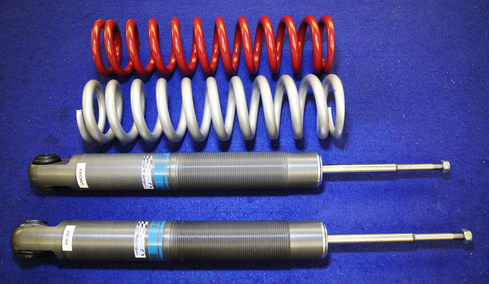 [/pic]
Over the next week, I will be fabricating the upper and lower spring seats and making some Delrin washers to isolate the springs against the seats to make on-vehicle adjustments easier and to locate the upper seat more precisely. I have ordered some original gaiters and bump-stops for now but will upgrade to closed cell bumpstops as soon as I have the final size I will need.
I suppose I could have waited until they were all done but getting these components on hand was a milestone I wanted to share.
I will post again on the final assembly of the units.
The test then will be the seat-of-the-pants road test to see how far out my calculations are!
8Tech
I now have the Eibach ERS (Eibach Race System) springs in my choice of length and rate as I have calculated. I now have the new coil-over strut bodies built and valved to suit the mass of the car and the spring rates to give a suitable suspension frequency.
[pic]
 [/pic]
Over the next week, I will be fabricating the upper and lower spring seats and making some Delrin washers to isolate the springs against the seats to make on-vehicle adjustments easier and to locate the upper seat more precisely. I have ordered some original gaiters and bump-stops for now but will upgrade to closed cell bumpstops as soon as I have the final size I will need.
I suppose I could have waited until they were all done but getting these components on hand was a milestone I wanted to share.
I will post again on the final assembly of the units.
The test then will be the seat-of-the-pants road test to see how far out my calculations are!
8Tech
Hey guys,
I am here to try and give some informative postings and if there is anything you would like me to try and explain a little more in depth, please ask.
I am sure there will be plenty more owners trying to understand what I am doing and why so please, just ask because I don't want to babble on explaining what I am doing if it makes a tedious read.
Cheers,
8Tech.
Ok guys, I have done a fair bit of work on the new suspension now, in fact, everything apart from the installation and testing. That is where we find whether my calculations were correct or close, or whether I need to go back to school!
This is going to be a lengthy post to read, but took a lot longer to post, so grab a beer or a coffee, and settle down. I have done the pictorial part first, so that if you are getting bored by the end, you need not troll through the technicalities.
Firstly, I will explain the form and function of the components, apart from the threaded damper bodies discussed earlier in this thread.
To install the Eibach ERS (Eibach Race System) springs, which are parallel coiled, the original top mount needed modification. As the ERS springs are ground ended, ie flat, whereas the Aston Martin springs are simply a cut coil, the top mount had to be machined flat for the spring seat, and the guide machined parallel......
[pic]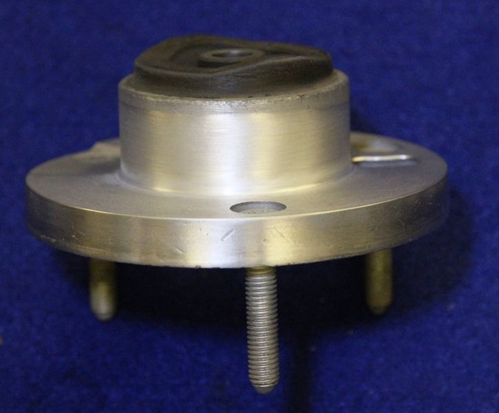 [/pic]
To accurately locate the upper end of the spring, and to give a bearing surface to the spring so that it could rotate, I manufactured a "Delrin" top-hat bush. This material has a very low friction coefficient and feels "waxy" to the touch. It is very strong and suitable as a sliding (but not running) bearing surface.
[pic]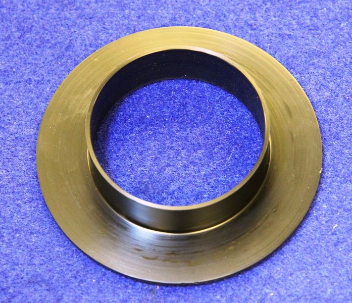 [/pic]
As previously seen, the new strut body is threaded so a pair of lower spring mounts were made, one (blue) as a locking ring, and the other (red) as the lower adjustable spring mount, similarly machined to the Delrin top to accurately locate the lower end of the spring.
[pic]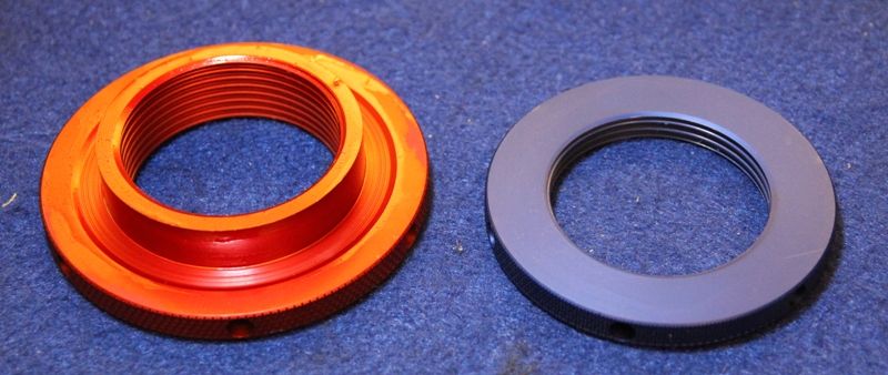 [/pic]
Here, we can see the location for either end. Top.........
[pic]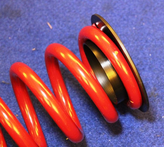 [/pic]
and bottom.......
[pic]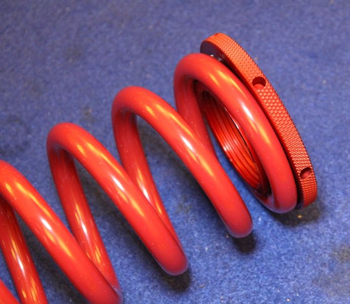 [/pic]
You can see here why I machined the upper mount parallel, so that the Delrin bush was a snug fit.
[pic]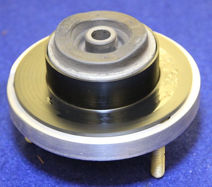 [/pic]
When a coil spring is compressed, it tries to unwind, and this is known as the torsion reaction, and can have a notable effect on component stress as well as the winding action actually affecting the spring rate, so I have installed some torsion release bearings on the lower mount instead of the Delrin I have used on the top. These 3 piece needle roller bearings........
[pic]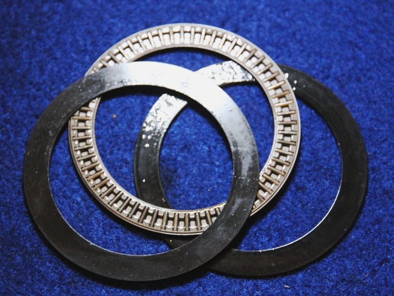 [/pic]
also have the advantage of making on-vehicle adjustments easier by reducing the seat friction. In this case, they are installed on my lower mount.
[pic]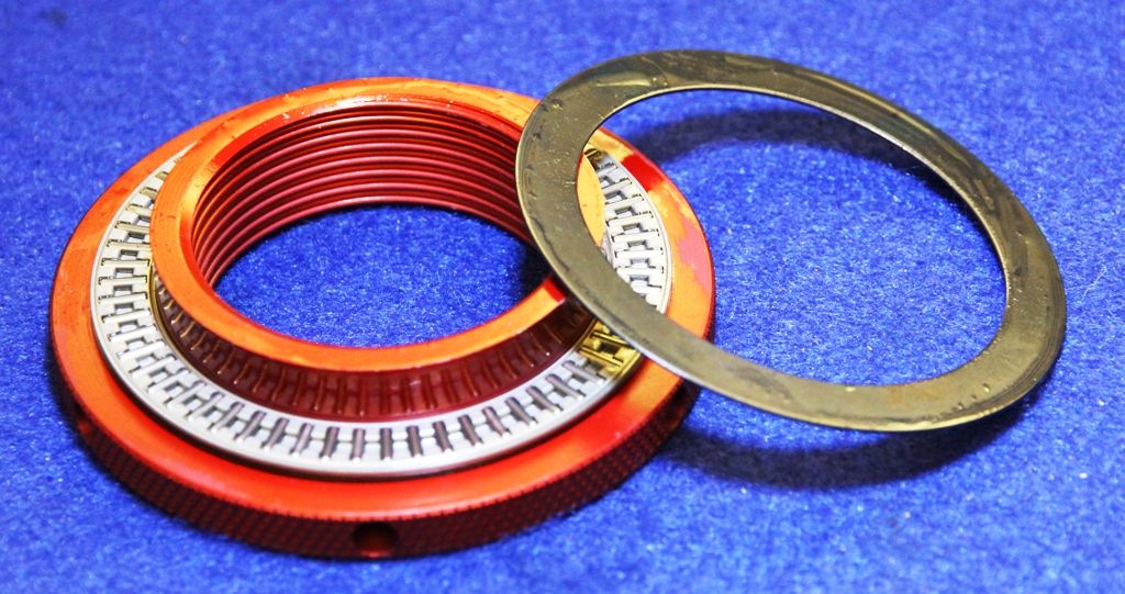 [/pic]
So here we have the strut assembly procedure........
After applying a light oil to the strut body threads, the locking ring is attached and wound to the bottom of the strut body.......
[pic]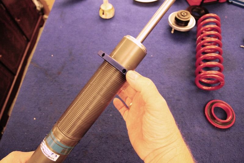 [/pic]
followed by the lower seat and torsion release bearing...........
[pic]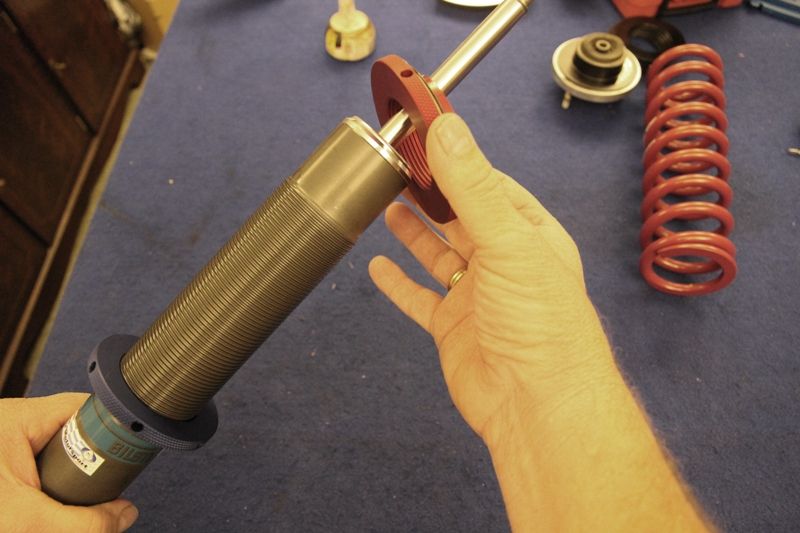 [/pic]
We can now install the 4 piece bump-stop/gaiter assembly.........
[pic]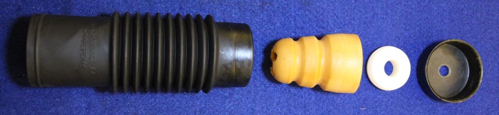 [/pic]
These consist of the soft plastic dirt shield, a nylon block that presses into the top of the bump-stop, and a metal shield washer.
After installing this, pre-assembled onto the strut body..........
[pic]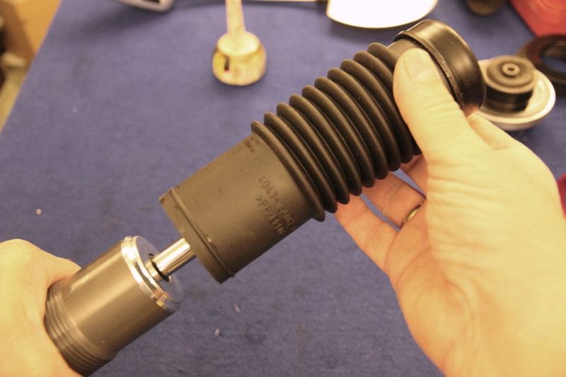 [/pic]
We can install the new spring..........
[pic]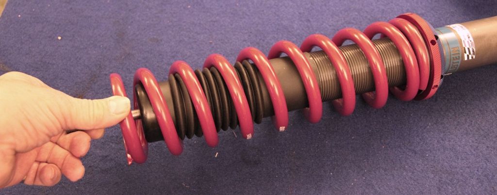 [/pic]
followed by the Delrin guide.........
[pic]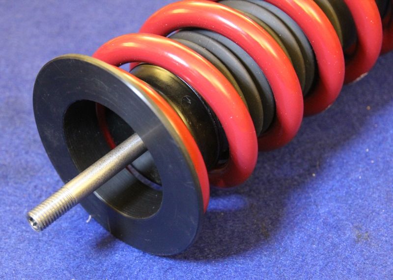 [/pic]
and top mount.
[pic]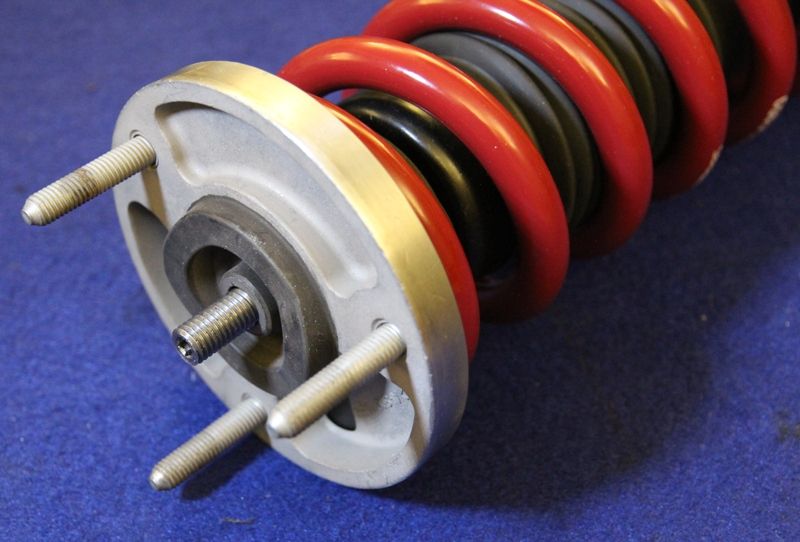 [/pic]
washer and new nyloc nut.
[pic]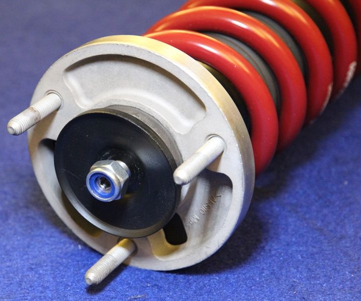 [/pic]
Using a go-thru 17mm socket and hex key, the top mount can now be fully tightened.
[pic]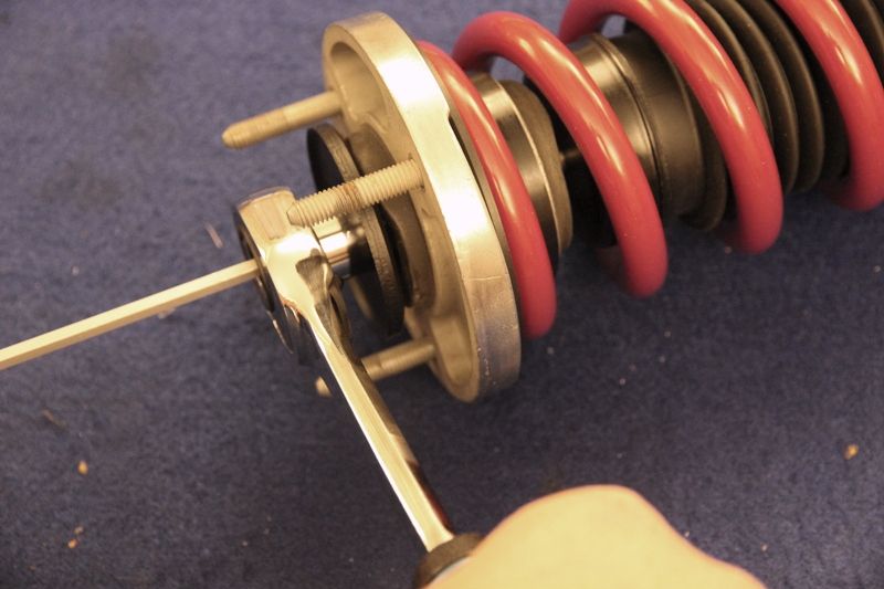 [/pic]
We can now screw the lower mount upwards to take up the slack in the spring, and as soon as the spring is properly located, with all the play adjusted out with the lower seat, we have the complete strut.
[pic]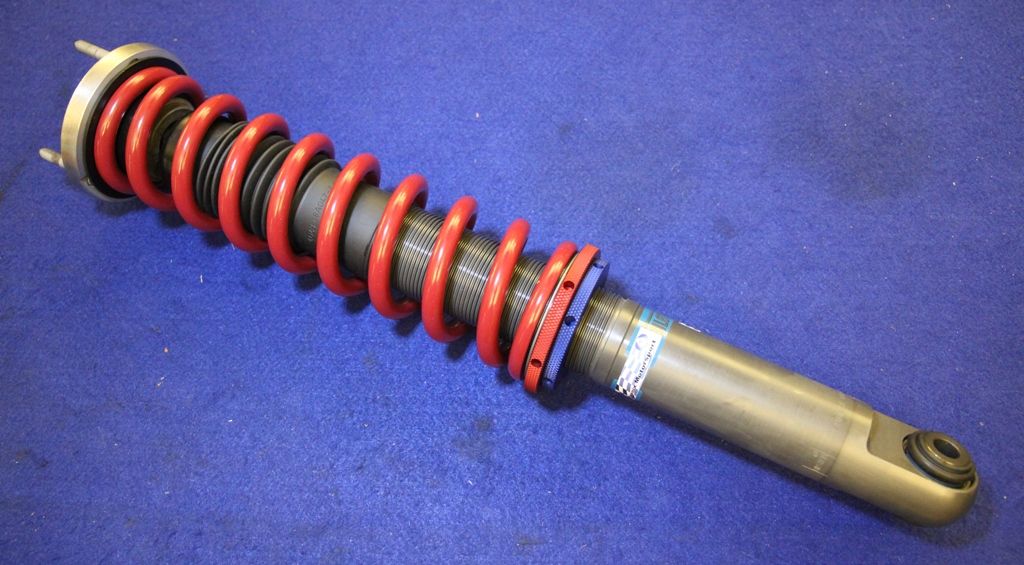 [/pic]
As I have selected a 12" free length spring, clearly the installation without pre-load will have an assembled free length of 12".
[pic]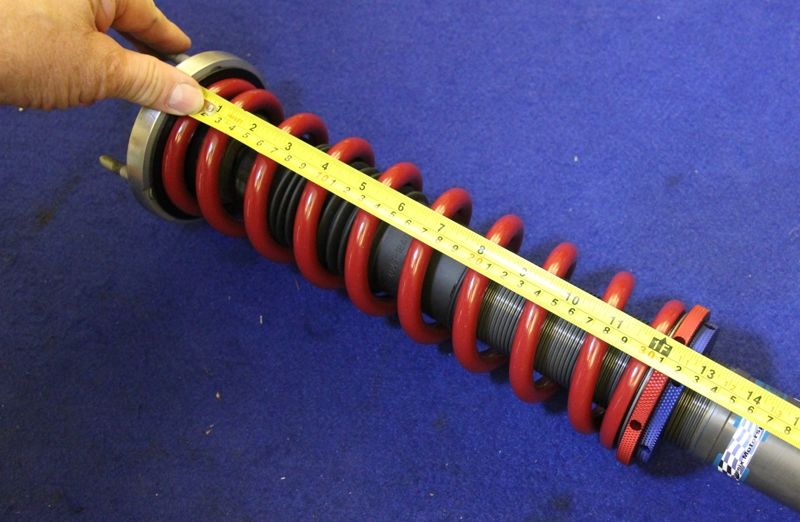 [/pic]
HOWEVER, as my calculations will show (hopefully!!), having no preload on the spring will have the car sitting too low, so I have calculated the required pre-load, and therefore installed length of the new, higher rate spring as 9.5" on the rear, and 9.75" on the front, with the new spring rates, to obtain the same ride height as the original softer springs at their original fixed installed length of 10.5" on 14" free length springs.
[pic]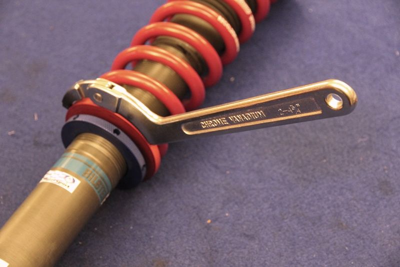 [/pic]
[pic]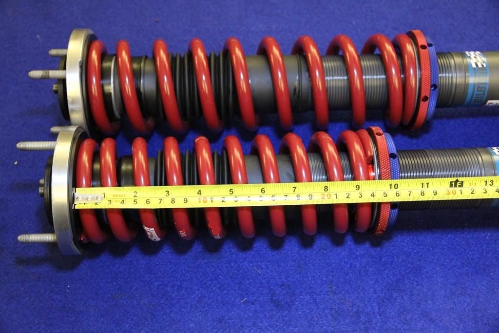 [/pic]
My choice of springs has now shown that at standard ride height, the spring adjustment is as near as dammit, smack in the middle of the adjustment range, making my selected length seem, at this point in time, correct.
[pic]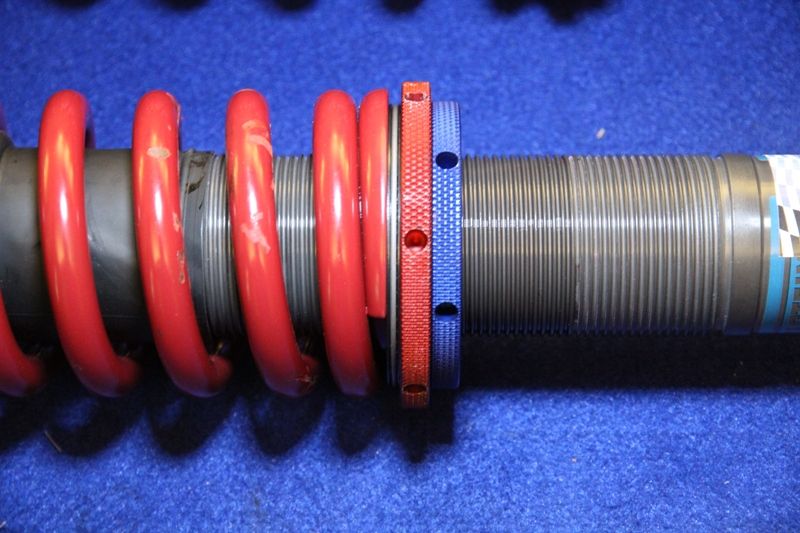 [/pic]
Of course, theory is one thing and results are another, so until the new struts are installed, and tested, there is still a margin of error possible, hopefully within the range of adjustment to fine-tune.
The Mathematics of the design.:
From my previous post, we found on the spring dynomometer, that the original spring rates were linear, and approximately 225lb/in for the front, and 315lb/in for the rear. I have decided to use a 50% uprated spring rate and have therefore selected a 350lb/in front and 450lb/in rear spring.
To find the support, ie upward force, offered by the original springs, we need to know their spring rates, and their compression. As they are 14" free length, and have a 10.5" installed length, this is a simple calculation.
Front = spring rate x compression = 225 x 3.5 = 780 lbs
Rear = spring rate x compression = 315 x 3.5 = 1100 lbs
So to calculate the required compression of our new springs to offer the same support:
Spring rate x compression = load, so compression = load / spring rate =
front = 780 / 350 = 2.25", rear = 1100 / 450 = 2.5".
Therefore, whatever spring free length we choose, they will need to be compressed by 2.25" and 2.5" respectively to offer the same support load, and therefore ride height as the original springs with a 3.5" compression.
Initial measurements showed that the length of the strut body would allow either a 14",12" or 10" free length spring to be fitted. As the 12" spring would hopefully be nearer the central adjustment position, and the reduction of travel offered by the median length spring was still within useable limits, there was a more important thing to consider. I examined the specs of each spring under consideration and here are the specifications........
Spring Spring Weight (Mass) Mass Mass (pair) Travel
14"x350lb 6.19lb 2810g 5620g 8.0"
14"x450lb 7.34lb 3330g 6660g 7.5"
12"x350lb 5.05lb 2290g 4580g 6.9"
12"x450lb 5.51lb 2500g 5000g 6.8"
As can be seen, as the total installed spring travel is under 2", and preload accounts for another 2.5", there is at least a further 2" travel available on even the most restricted 12" spring.
However, using 12" springs instead of 14" springs saves a total of (5620 + 6660) - (4580 + 5000) = 2700g.
With convention suggesting 50% of the spring mass being accepted as unsprung weight, we are saving a stonking 1350g of unsprung weight, just by using the shorter springs. Consider that AM consider a £400 set of Titanium wheel nuts saving just a few grams as noteworthy and you can see the advantage. I decided against using 10" springs as they brought the travel issue too close to coil bind on the shorter spring.
I have had the dampers valved to compensate for the increase in spring rate.
We can now calculate the spring rate as seen at the wheel, called, surprisingly, the wheel rate. This is not the same as the spring rate because the wheel has a mechanical (leverage) advantage over the strut, and to calculate this, we need to know the "Motion Ratio".
Diagram courtesy of Eibach Motorsport.
[pic]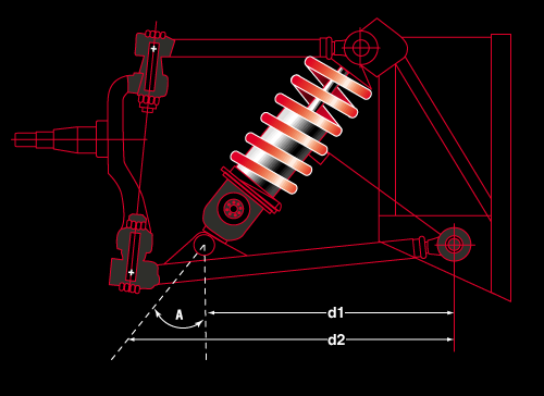 [/pic]
As the Aston Martin has "A-Arm" suspension rather than the more common McPherson strut arrangement, then the Motion Ratio is simply the mechanical advantage the wheel has, pushing the balljoint up, over the strut has resisting it.
This ratio is calculated as Motion Ratio = Spring centerline distance D1 / Balljoint pivot distance D2.
Unfortunately, as the Aston Martin strut is not parallel to the direction of travel, but sits at an angle "A", then we need to include the cosine of this angle into the calculation.
The formula then becomes........
wheel rate = motion ratio squared x spring rate x cosine "A".
Once we have the wheel rate as seen by the car, we can calculate the natural frequency of the suspension front and rear. We need to do this because it is this frequency that gives the impression of an uncomfortable ride quality. The human body persieves frequencies between 1 and 2 Hz (cycles per second) vertically as comfortable, and this is believed to be due to that being the body's verticl rate between walking and running. Lower ratescan induce motion sickness and higher rates feel very harsh.
The suspension frequency can now be calculated from the following.......
Suspension frequency = 188 x (wheel rate / vehicle sprung weight) / 60
As I have had to estimate the unsprung weight, by knowing the corner weights of the car and subtracting 15% as an estimate for the unsprung weight, and calculate the motion ratio from angles measured under adverse conditions, this could be where my calculations are more estimates, but I am fairly confident, I am in the right area at 2.0 - 2.5 Hz, the frequency of a high performance sports car. Rear suspension frequency is marginally higher than the front so that following a bump, the rear frequency will "catch up" with the front and the car will not pitch front to rear.
I have not taken into consideration the tyre spring and damping effect as it will only account for a 2% error at most.
A very simplistic explanation of damping ration would be the actual errect it has. A ration of 0.0 would be undamped and so the spring would keep the vehicle bouncing almost indefinately, so most passenger cars have a ratio of 0.2 where following a bump, the vehicle will bounce up and down a couple of times before settling, 0.4 and it will bounce once and 0.6 will damp it to the extent that it will settle after just the rebound. Critical damping of 1.0 damps the strut so that there is no overshoot of the suspension position prior to the bump. Values over 1.0 will damp the travel, delaying the rebound against the spring force. I have set damping at 0.3, a value between a normal passenger car and a car set up mainly as a track car.
Certainly better than just changing a set of springs and doing nothing else.
I will report when all fitted and tested.
8Tech.
This is going to be a lengthy post to read, but took a lot longer to post, so grab a beer or a coffee, and settle down. I have done the pictorial part first, so that if you are getting bored by the end, you need not troll through the technicalities.
Firstly, I will explain the form and function of the components, apart from the threaded damper bodies discussed earlier in this thread.
To install the Eibach ERS (Eibach Race System) springs, which are parallel coiled, the original top mount needed modification. As the ERS springs are ground ended, ie flat, whereas the Aston Martin springs are simply a cut coil, the top mount had to be machined flat for the spring seat, and the guide machined parallel......
[pic]
 [/pic]
To accurately locate the upper end of the spring, and to give a bearing surface to the spring so that it could rotate, I manufactured a "Delrin" top-hat bush. This material has a very low friction coefficient and feels "waxy" to the touch. It is very strong and suitable as a sliding (but not running) bearing surface.
[pic]
 [/pic]
As previously seen, the new strut body is threaded so a pair of lower spring mounts were made, one (blue) as a locking ring, and the other (red) as the lower adjustable spring mount, similarly machined to the Delrin top to accurately locate the lower end of the spring.
[pic]
 [/pic]
Here, we can see the location for either end. Top.........
[pic]
 [/pic]
and bottom.......
[pic]
 [/pic]
You can see here why I machined the upper mount parallel, so that the Delrin bush was a snug fit.
[pic]
 [/pic]
When a coil spring is compressed, it tries to unwind, and this is known as the torsion reaction, and can have a notable effect on component stress as well as the winding action actually affecting the spring rate, so I have installed some torsion release bearings on the lower mount instead of the Delrin I have used on the top. These 3 piece needle roller bearings........
[pic]
 [/pic]
also have the advantage of making on-vehicle adjustments easier by reducing the seat friction. In this case, they are installed on my lower mount.
[pic]
 [/pic]
So here we have the strut assembly procedure........
After applying a light oil to the strut body threads, the locking ring is attached and wound to the bottom of the strut body.......
[pic]
 [/pic]
followed by the lower seat and torsion release bearing...........
[pic]
 [/pic]
We can now install the 4 piece bump-stop/gaiter assembly.........
[pic]
 [/pic]
These consist of the soft plastic dirt shield, a nylon block that presses into the top of the bump-stop, and a metal shield washer.
After installing this, pre-assembled onto the strut body..........
[pic]
 [/pic]
We can install the new spring..........
[pic]
 [/pic]
followed by the Delrin guide.........
[pic]
 [/pic]
and top mount.
[pic]
 [/pic]
washer and new nyloc nut.
[pic]
 [/pic]
Using a go-thru 17mm socket and hex key, the top mount can now be fully tightened.
[pic]
 [/pic]
We can now screw the lower mount upwards to take up the slack in the spring, and as soon as the spring is properly located, with all the play adjusted out with the lower seat, we have the complete strut.
[pic]
 [/pic]
As I have selected a 12" free length spring, clearly the installation without pre-load will have an assembled free length of 12".
[pic]
 [/pic]
HOWEVER, as my calculations will show (hopefully!!), having no preload on the spring will have the car sitting too low, so I have calculated the required pre-load, and therefore installed length of the new, higher rate spring as 9.5" on the rear, and 9.75" on the front, with the new spring rates, to obtain the same ride height as the original softer springs at their original fixed installed length of 10.5" on 14" free length springs.
[pic]
 [/pic]
[pic]
 [/pic]
My choice of springs has now shown that at standard ride height, the spring adjustment is as near as dammit, smack in the middle of the adjustment range, making my selected length seem, at this point in time, correct.
[pic]
 [/pic]
Of course, theory is one thing and results are another, so until the new struts are installed, and tested, there is still a margin of error possible, hopefully within the range of adjustment to fine-tune.
The Mathematics of the design.:
From my previous post, we found on the spring dynomometer, that the original spring rates were linear, and approximately 225lb/in for the front, and 315lb/in for the rear. I have decided to use a 50% uprated spring rate and have therefore selected a 350lb/in front and 450lb/in rear spring.
To find the support, ie upward force, offered by the original springs, we need to know their spring rates, and their compression. As they are 14" free length, and have a 10.5" installed length, this is a simple calculation.
Front = spring rate x compression = 225 x 3.5 = 780 lbs
Rear = spring rate x compression = 315 x 3.5 = 1100 lbs
So to calculate the required compression of our new springs to offer the same support:
Spring rate x compression = load, so compression = load / spring rate =
front = 780 / 350 = 2.25", rear = 1100 / 450 = 2.5".
Therefore, whatever spring free length we choose, they will need to be compressed by 2.25" and 2.5" respectively to offer the same support load, and therefore ride height as the original springs with a 3.5" compression.
Initial measurements showed that the length of the strut body would allow either a 14",12" or 10" free length spring to be fitted. As the 12" spring would hopefully be nearer the central adjustment position, and the reduction of travel offered by the median length spring was still within useable limits, there was a more important thing to consider. I examined the specs of each spring under consideration and here are the specifications........
Spring Spring Weight (Mass) Mass Mass (pair) Travel
14"x350lb 6.19lb 2810g 5620g 8.0"
14"x450lb 7.34lb 3330g 6660g 7.5"
12"x350lb 5.05lb 2290g 4580g 6.9"
12"x450lb 5.51lb 2500g 5000g 6.8"
As can be seen, as the total installed spring travel is under 2", and preload accounts for another 2.5", there is at least a further 2" travel available on even the most restricted 12" spring.
However, using 12" springs instead of 14" springs saves a total of (5620 + 6660) - (4580 + 5000) = 2700g.
With convention suggesting 50% of the spring mass being accepted as unsprung weight, we are saving a stonking 1350g of unsprung weight, just by using the shorter springs. Consider that AM consider a £400 set of Titanium wheel nuts saving just a few grams as noteworthy and you can see the advantage. I decided against using 10" springs as they brought the travel issue too close to coil bind on the shorter spring.
I have had the dampers valved to compensate for the increase in spring rate.
We can now calculate the spring rate as seen at the wheel, called, surprisingly, the wheel rate. This is not the same as the spring rate because the wheel has a mechanical (leverage) advantage over the strut, and to calculate this, we need to know the "Motion Ratio".
Diagram courtesy of Eibach Motorsport.
[pic]
 [/pic]
As the Aston Martin has "A-Arm" suspension rather than the more common McPherson strut arrangement, then the Motion Ratio is simply the mechanical advantage the wheel has, pushing the balljoint up, over the strut has resisting it.
This ratio is calculated as Motion Ratio = Spring centerline distance D1 / Balljoint pivot distance D2.
Unfortunately, as the Aston Martin strut is not parallel to the direction of travel, but sits at an angle "A", then we need to include the cosine of this angle into the calculation.
The formula then becomes........
wheel rate = motion ratio squared x spring rate x cosine "A".
Once we have the wheel rate as seen by the car, we can calculate the natural frequency of the suspension front and rear. We need to do this because it is this frequency that gives the impression of an uncomfortable ride quality. The human body persieves frequencies between 1 and 2 Hz (cycles per second) vertically as comfortable, and this is believed to be due to that being the body's verticl rate between walking and running. Lower ratescan induce motion sickness and higher rates feel very harsh.
The suspension frequency can now be calculated from the following.......
Suspension frequency = 188 x (wheel rate / vehicle sprung weight) / 60
As I have had to estimate the unsprung weight, by knowing the corner weights of the car and subtracting 15% as an estimate for the unsprung weight, and calculate the motion ratio from angles measured under adverse conditions, this could be where my calculations are more estimates, but I am fairly confident, I am in the right area at 2.0 - 2.5 Hz, the frequency of a high performance sports car. Rear suspension frequency is marginally higher than the front so that following a bump, the rear frequency will "catch up" with the front and the car will not pitch front to rear.
I have not taken into consideration the tyre spring and damping effect as it will only account for a 2% error at most.
A very simplistic explanation of damping ration would be the actual errect it has. A ration of 0.0 would be undamped and so the spring would keep the vehicle bouncing almost indefinately, so most passenger cars have a ratio of 0.2 where following a bump, the vehicle will bounce up and down a couple of times before settling, 0.4 and it will bounce once and 0.6 will damp it to the extent that it will settle after just the rebound. Critical damping of 1.0 damps the strut so that there is no overshoot of the suspension position prior to the bump. Values over 1.0 will damp the travel, delaying the rebound against the spring force. I have set damping at 0.3, a value between a normal passenger car and a car set up mainly as a track car.
Certainly better than just changing a set of springs and doing nothing else.
I will report when all fitted and tested.
8Tech.
Edited by 8Tech on Sunday 13th October 19:28
Gassing Station | Aston Martin | Top of Page | What's New | My Stuff