Cylinder Head - Whats This Thread Size?
Discussion


A quick question to the Rover V8 experts on the forum if I may 

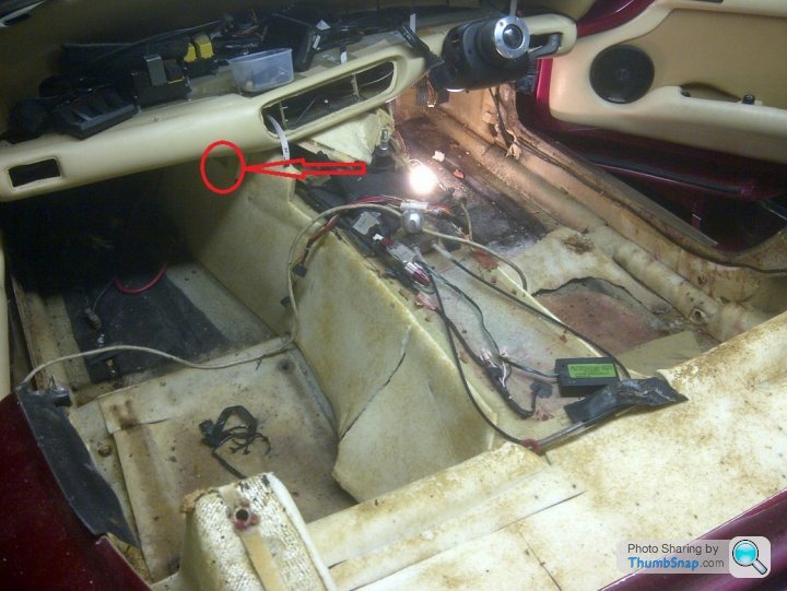
Can someone confirm the above circled thread size please, I'm assuming UNC but need an exact size?

I know the above Land Rover factory earth stud fitted lower on the cylinder head is 5/16 UNC, but its tricky to get at so I'm looking to use the higher unused threaded hole above it as demonstrated by John Halstead below...

Is the threaded hole John Halstead is using here the same 5/16 UNC thread as the lower Land Rover factory earthing point circled in red, or is it a smaller size as I suspect?
Thanks in advance, Dave
Can someone confirm the above circled thread size please, I'm assuming UNC but need an exact size?
I know the above Land Rover factory earth stud fitted lower on the cylinder head is 5/16 UNC, but its tricky to get at so I'm looking to use the higher unused threaded hole above it as demonstrated by John Halstead below...
Is the threaded hole John Halstead is using here the same 5/16 UNC thread as the lower Land Rover factory earthing point circled in red, or is it a smaller size as I suspect?
Thanks in advance, Dave

spitfire4v8 said:
On the engine I've got on the floor right now all those end-of-head threaded holes on the heads are all the same size/thread
Steve_D said:
The two positions you are questioning are the same size..... 3/8 UNC.
So your earth stud can be fitted where you like.Steve
ETA do first consider if the upper position will foul the bulkhead...would be bloody close on my Chim.
Excellent chaps, many thanks So your earth stud can be fitted where you like.Steve
ETA do first consider if the upper position will foul the bulkhead...would be bloody close on my Chim.
And a good point there from Steve re the clearance, it's something I'll need to look at closely tonight but I suspect you're right and it'll also be a right PITA to use as an earthing point

My idle valve still loops the priming pulse so I've removed it and fitted a temporary manual idle valve of my own design which actually works brilliantly, it also proves just how little extra air the engine actually needs on cold start and that the warm engine definitely benefits in idle quality and drivability with no extra air at all.
My TVR dives great but I have recorded a number of voltage drops around the car so given this and my idle valve/looping priming pulse issue I'll definitely be focusing on improving my earths over the next few months. I know Land Rover fitted a host of engine earths including choosing that point on the rear of the N/S cylinder head, I assume there was good reason for this location choice, perhaps spitfire4v8 can offer up the reasoning and theory behind this?
It's my understanding TVR gave the engine itself just two earths:
1. One that runs from the O/S of the block (near the oil pressure switch) to a stud on the chassis outrigger diagonal
2. One on the back of N/S cylinder head as used by Land Rover
The thing is while I know I have the O/S block to chassis diagonal earth, to be honest I'm yet to confirm I have the second earth at the back of the N/S head? Does anyone know if TVR always used this earthing point on the head, I've seen evidence that suggests TVR may have been typically inconsistent in using this Land Rover factory earthing point
If my engine is indeed only earthed from block to the outrigger diagonal I'm confident there is significant scope for improvement

Quite clearly a Range Rover benefits from a metal body (all be it ally not steel), this clear earthing advantage being conspicuous by its absence on a fiberglass Chimaera so TVR relied on the chassis as the earth return path back to the battery which in my experience with Lotus cars is proven to be less satisfactory, especially when you factor in the inevitable corrosion that will have accumulated in the past 20 plus years or more on our cars.
Comments welcomed, Dave.
Belle427 said:
When i had my heads off i chose to move the factory negatives to the bolt hole you suggest for access reasons. I also added a new cable from there back to battery negative just to be sure.
Interesting So your TVR did originally have an earth cable bolted to this lower flange of the head then?
(See the red circle to the left of the image)

When you switched the cable to the higher up 3/8 UNC bolt hole did you do so when the head was off?
Can you now access the higher up 3/8 UNC bolt hole now the head is back on, or would you consider the clearance too tight to the bulkhead?
Thanks for your input
Belle427 said:
From memory factory multiple earths to the bolt circled originally.
That's as Land Rover intended then, to confirm TVR always did it this way ideally we need someone like Steve_D who's done a lot of body off chassis restorations to share what he normally finds here Belle427 said:
Access is fine to the new location with no bulkhead fouling, carried out with heads on, I will add a picture later.
Excellent, that's super helpful I have never seen an engine earth fitted to that stud.
My circuit diagram only has the lambdas earthing at that point.
There is normally only the one engine/chassis earth which normally runs from timing cover to the stud on the chassis in the wheel well.
Have a car in at present which has a 35mm sq. positive cable from the battery to the starter. It then has a negative cable from top of tunnel to battery. This cable is best described as a 'bit of string' which completely negates the benefit of the meaty pos. cable. I will be changing it.
Steve
Belle427 said:
Difficult to see but here is the stud i fitted, i did it without plenum top in place which allowed access.

Many thanks, that looks like a quality additional engine earth to me and replicates exactly what John Halstead did on the orange supercharged and Emerald ECU equipped Chimaera he built, it's also where I'm planning to relocate my additional battery to block earth cable I fitted way back in 2012.Detail here:
https://www.pistonheads.com/gassing/topic.asp?h=0&...
Unfortunately for some reason the guy who made my cables up fitted a very small tube terminal to the earth lead, this meant the only bolt to block I could use was one of the tiny fixings for the tin flywheel shield which was far from ideal, as we know an engine earth should use a nice stout bolt so I've been meaning to sort this since fitting.
Steve_D said:
I have never seen an engine earth fitted to that stud, my circuit diagram only has the lambdas earthing at that point
Thanks Steve, so the lighter gauge earths we can see in Belle427's above image are for the 14CUX narrow band lambda sensors, that's useful information for everyone on the forum. Steve_D said:
There is normally only the one engine/chassis earth which normally runs from timing cover to the stud on the chassis in the wheel well.
Again this is very useful/revealing information and exactly as I'd suspected, thanks for confirming this as it proves just how reliant a TVR Chimaera is on that one and only engine to chassis earthing point, I was always taught it is best practice to have at least two engine earths:1. One from somewhere on the front of the engine block to the steel body, the alternator bolt being ideal as it also helps to get the best from the rectifier, obviously a TVR has no steel body so on a fiberglass car the chassis should be used
2. One from the rear of the block directly back to battery using a stout cable of the same gauge as used for the live feed to the starter, the rear block earthing point should preferably be one of the starter bolts to ensure best cranking performance
With just one engine earth (timing cover to outrigger diagonal) and the very long string thin starter cable used by TVR it's no wonder these fiberglass bodied cars suffer from slow cranking and hot start no cranking issues. Add in a few years of corrosion on that very exposed outrigger diagonal stud and general starter cable corrosion and it's virtually inevitable there will be issues.
Of course the requirement for sound engine earthing goes way beyond cranking, engine sensor accuracy, correct stepper motor/idle valve functioning, the charging system, and the entire ignition system are all completely reliant on sound earthing. Quite simply TVR's idea of relying on just one main engine earth for absolutely everything is very poor indeed, especially given there is no metal body!
Steve_D said:
Have a car in at present which has a 35mm sq. positive cable from the battery to the starter. It then has a negative cable from top of tunnel to battery. This cable is best described as a 'bit of string' which completely negates the benefit of the meaty pos. cable. I will be changing it.Steve
Very sensible, I've decided to invest in a proper hydraulic cable crimping tool so I can finally make up my own properly crimped heavy gauge cables at will rather than outsourcing this work. After fitting a larger tube terminal I will be relocating my additional earth cable from the tin flywheel shield to that far more suitable upper head hole as used by both John Halstead & Belle427, I'll link this to the lower starter bolt and then on to that chassis diagonal stud, finally I'll fit another run from the chassis diagonal stud to the block at one of the alternator mounting bolts. My bet is after that lot my ECU looping priming pulse issue will vanish and my PWM Bosch idle valve will finally function correctly, many thanks for everyone who has contributed to this post, without exception the information provided has been extremely helpful

As per steve d's post above, TVR never fitted an earth to battery from the nearside head, the only heavy duty earth is the one to the offside chassis tube. An additional earth is a good idea!
The nearside head earth does have the lambdas on it, but also an earth connection for the immobiliser. I've not investigated if it's required or not, but always put it back in when I do an ECU loom just in case it's important.
Also don't forget the ECU/loom earths on the engine front cover stud just next to the oil light switch. I can't remember what earths there except for the air con clutch but I seem to think there's at least one ecu earth to that point too. There are 3 main ecu grounds in total and also powered items such as the air con clutch mentioned earlier and immobiliser, air flow meter, lambdas, diagnostic plug socket and possibly more i've forgotten...
spitfire4v8 said:
As per steve d's post above, TVR never fitted an earth to battery from the nearside head, the only heavy duty earth is the one to the offside chassis tube. An additional earth is a good idea!
The nearside head earth does have the lambdas on it, but also an earth connection for the immobiliser. I've not investigated if it's required or not, but always put it back in when I do an ECU loom just in case it's important.
Very helpful again, thanks for sharing The nearside head earth does have the lambdas on it, but also an earth connection for the immobiliser. I've not investigated if it's required or not, but always put it back in when I do an ECU loom just in case it's important.
Out of interest do you earth your Emerald ECUs to the block at that point, or direct to the battery?
spitfire4v8 said:
Also don't forget the ECU/loom earths on the engine front cover stud just next to the oil light switch. I can't remember what earths there except for the air con clutch but I seem to think there's at least one ecu earth to that point too. There are 3 main ecu grounds in total and also powered items such as the air con clutch mentioned earlier and immobiliser, air flow meter, lambdas, diagnostic plug socket and possibly more i've forgotten...
More helpful info, on my car I've seen a bunch of earths on that front cover bolt, I guess along with the original 14CUX ECU being earthed here the additional wires are other engine sensors then? Here's an image I found, mine looks the same.

A casual observation from me would be that head earth stud must see a lot of heat on a TVR as it's very close to number 7 cylinder's header pipe and trapped there between it and the bulkhead
All this aside my overriding observation remains the same, that being the TVR idea of solely relying on that one block to chassis outrigger diagonal stud for so many earths is a problem waiting to happen, especially given the exposed location of that chassis stud. I accept it's automotive engine management wiring best practice for the ECU and sensors to be star earthed to the engine at one point but to rely on that same point for everything including brutal engine cranking duties seems plain wrong to me

Quite clearly as a minimum TVR should have also added a nice stout cable from one of the starter motor mounting bolts directly back to the battery, if they'd done this and hadn't wired the Meta immobiliser relay circuits back to front the car never would have earned it's reputation for slow and sometimes no starts when hot.
A cheap and simple fix on everyone's list should be:
1. Uprate the original string thin starter cable itself
2. Add a second stout cable from a starter bolt directly back to the battery negaive terminal
3. Bypass the immobiliser on the starter circuit (I can supply instructions for this), or better still fit a new immobiliser and wire it correctly which TVR clearly failed to do themselves
You'll notice I have not included the ModWise Hot Start Kit (just a relay), this post being further proof it's creator completely misunderstood the true reason our cars often suffer starting issues.
Edited by ChimpOnGas on Wednesday 23 January 09:27
On my emerald wiring I take non-ecu related earths to the battery negative.
Any ecu related earths and lambda earths are each on their own ring terminal and into my new looms I put 4 separate earth wires back into the car. Each of these goes to one each of the four 6mm tappings on the inlet manifold (there are 8 tappings, the outer four hold the fuel rail in place, the inner four are not used for anything on the tvrs so I use all four for earths back into the car).
So .. one earth point is for the immobiliser earth wire mentioned previously, one is for the ecu main earth, one is for the lambda sensor earth, and I always put in a spare back into the car just in case I ever need to wire anything else to earth that might be ecu offset affected, and this goes on the fourth 6mm ring terminal.
Different people have different ideas about earthing multiple items, but I have found over the years that separate earths back to easily accessible earth points on the engine (the inlet being one common ground plane), tight and clean gives no ecu / lambda voltage offsets. I've seen people earthing the ecu related items back to the battery but i was always told that's a no-no but I guess as long as everything is electrically sound then that would be fine, but as we know it's not always that way.
spitfire4v8 said:
On my emerald wiring I take non-ecu related earths to the battery negative.
Any ecu related earths and lambda earths are each on their own ring terminal and into my new looms I put 4 separate earth wires back into the car. Each of these goes to one each of the four 6mm tappings on the inlet manifold (there are 8 tappings, the outer four hold the fuel rail in place, the inner four are not used for anything on the tvrs so I use all four for earths back into the car).
So .. one earth point is for the immobiliser earth wire mentioned previously, one is for the ecu main earth, one is for the lambda sensor earth, and I always put in a spare back into the car just in case I ever need to wire anything else to earth that might be ecu offset affected, and this goes on the fourth 6mm ring terminal.
Different people have different ideas about earthing multiple items, but I have found over the years that separate earths back to easily accessible earth points on the engine (the inlet being one common ground plane), tight and clean gives no ecu / lambda voltage offsets. I've seen people earthing the ecu related items back to the battery but i was always told that's a no-no but I guess as long as everything is electrically sound then that would be fine, but as we know it's not always that way.
Oh my word that's impressive, respect Any ecu related earths and lambda earths are each on their own ring terminal and into my new looms I put 4 separate earth wires back into the car. Each of these goes to one each of the four 6mm tappings on the inlet manifold (there are 8 tappings, the outer four hold the fuel rail in place, the inner four are not used for anything on the tvrs so I use all four for earths back into the car).
So .. one earth point is for the immobiliser earth wire mentioned previously, one is for the ecu main earth, one is for the lambda sensor earth, and I always put in a spare back into the car just in case I ever need to wire anything else to earth that might be ecu offset affected, and this goes on the fourth 6mm ring terminal.
Different people have different ideas about earthing multiple items, but I have found over the years that separate earths back to easily accessible earth points on the engine (the inlet being one common ground plane), tight and clean gives no ecu / lambda voltage offsets. I've seen people earthing the ecu related items back to the battery but i was always told that's a no-no but I guess as long as everything is electrically sound then that would be fine, but as we know it's not always that way.
, I also believe it's also quite different to what I have.My Canems ECU main earth is to the battery, however, when I fitted my most recent replacement Canems Dual Fuel ECU, and because the car initially refused to start, the ECU maker himself instructed me to bare the braided shielding on the crank signal wire and earth it at the battery where the ECU is also earthed. This did seem odd to me at the time but I thought I'd better follow his instructions as he is after all the designer and builder of the ECU so I figured he must be guiding me correctly?
Baring the braided shielding on the crank signal wire and earthing it at the battery did indeed solve the no start issue immediately, however from that day on I also gained a frustrating and potentially unsafe looping priming pulse issue, something I'd never suffered before
 . After six months of suffering the looping issue and a huge number of emails the installers eventually agreed to take the car back, off it went to Lloyds who spent some considerable time in their words "tidying up my wiring" (not my wiring BTW) which I believe included the relocation of the crank signal earth to battery the ECU maker himself instructed me to execute.
 Three weeks later I was reassured the car was fixed and ready to collect, so off I go again with the help of a good friend to complete the 200 mile round trip to Waminster, but sadly within days the looping issue was back

While the work was done FOC the car had been with Lloyds for many weeks which was both frustrating and inconvenient especially given the fault it went in with promptly returned within days, clearly it was not fixed at all. So after just a few days with the car back in my hands and the looping issue back with a vengeance I decided it would be faster and possibly more effective if I just took ownership and investigated the issue myself, within 40 minutes I'd traced the source of what I believe is an earth loop to the patern part Bosch idle valve or it's associated wiring/earthing arrangement because I could literally turn the looping fault on and off at will simply by disconnecting and reconnecting the PWM idle valve.
Obviously the PWM idle valve is a fundamental and integral element of the Canems system/installation, ironically the ECU is designed to control the PWM idle valve not be adversely affected by it, clearly something else was a miss
My admittedly crude (but very effective) solution was to remove the idle valve completely, but realising the engine does need a little help to idle from cold I deployed temperature corrected ignition timing and scatter spark which solved 95% of the extra idle speed requirement from cold without actually applying any extra air. However, I did eventually have to concede the engine still needed a little extra air on cold start cranking and during the warm up period between a stone cold start and 40c coolant temp.
Above 40c coolant temp it became clear the engine requires no additional air whatsoever, indeed it benefits from no air passing through the PWM idle valve which I discovered was never actually fully closed. Below this threshold my solution for extra air was laughably simple and took the form of a London taxi heater valve operated from the drivers seat via a choke cable arrangement, pull the knob out and crank and she bursts into life at a steady 1,100rpm idle from dead cold, push the knob slowly in as the engine warms for the first two minutes or so and after that it can be completely pushed home and left that way for the rest of the day until the next proper cold start the following morning.
My simple manual idle valve delivers no looping priming pulse issues, brisk cold starts, smoother idling when the engine is warm, more consistent AFRs and better low speed drivability. I'm convinced my PWM idle valve was doing things the duty readings on my laptop weren't displaying, not only did the idle valve cause the ECU looping issue but I now genuinely believe the PWM idle valve was randomly opening and closing without my knowledge all along.
Clearly the moral of the story teaches us just how important proper earthing is where engine management is concerned, it also further reinforces the importance of a quality loom on any aftermarket ECU installation. The standard TVR loom is already a splice between TVR's own suspect efforts and the 14CUX engine loom they sourced with the engine direct from Land Rover, when moving to an after market ECU installation that retains elements of the original engine loom you could easily argue it becomes a splice on a splice on third a splice (the new engine management system).
The likelihood of introducing potential differences between earth points (earth loops) is extremely high unless best practice automotive engine management wiring best practices are rigorously observed and followed.
Dave.
Edited by ChimpOnGas on Wednesday 23 January 11:42

Belle427 said:
The battery to tunnel negative cable, is it a nightmare to get at to change it?
I thought about creating a new negative point somewhere in the engine bay more accessible but chassis access to drill isnt great.
Yes it is.I thought about creating a new negative point somewhere in the engine bay more accessible but chassis access to drill isnt great.
Plus it is a prime candidate for bad earths. A bolt passes through a brass bush moulded into the GF of the body and then into the chassis. Because of its location and only being able to get a spanner on it at best it is difficult to get the bolt tight. In use the body must move a little which again most make this a less than ideal earth point.
Steve
Hedgehopper said:
I couldn't find the n/s earth to the engine either. I made up a new earth cable and ran it from the o/s outrigger diagonal to one of the starter motor fixing bolts,
I'm afraid to point out like that the starter is still relying on the chassis as the earth return, and the chassis element is the sketchy bit to say the least . Actually the way TVR did things it's not just the chassis used, current also needs to travel from the chassis earth point on the passenger side of the tunnel down a second run of cable they fixed there before it finally gets back to the battery.

At each point where chassis meets cable/tube terminal there's a connection..... and with each connection there will definitely be resistance, If you measure the resistance between that stud on the outrigger diagonal to that chassis point on the tunnel I'd bet it'll be a significant figure, if you then measure the entire earth return including TVR's cable that runs from the tunnel to the battery I bet it'll be even greater still.
It's all resistance, particularity that of the chassis and all the cable connections, and it's this resistance you're looking to mitigate.
As the starter is bolted to the block, and the block is earthed to the stud on the outrigger diagonal (the chassis) anyway, all you've effectively done by linking the chassis stud to the starter bolt is add another path from block to chassis stud. It's better than nothing as your copper cable will offer less resistance than the ally engine block, but the improvement will be minimal compared with adding cable from that starter bolt directly to the battery because this way you completely bypass the less than ideal TVR arrangement of using the chassis and yet another cable (tunnel chassis earthing point) to get the current back to the battery.
You're some of the way there, but to complete the job and get the best results I'd seriously consider running another cable from that starter bolt over the bell housing and connecting it directly back to the battery, this will completely bypass the corrosion prone chassis path and will significantly reduce the number of resistance prone cable connections used in the standard TVR arrangement too.
To be clear the above is not a criticism, just a suggestion to make the good work you've already started a more complete solution, hope it helps?
During my strip down of the car I took some (a lot) of pictures. 
Maybe these photos will help others.
My car is a 1993 4.3L
This bolted cable is under the Alternator bracket (Pre-serpentine) and goes to the diagonal earth stud on the offside. (Behind the front wheel)

This bolt /stud is on the nearside behind the rocker cover. (exhaust has been removed)

Maybe these photos will help others.
My car is a 1993 4.3L
This bolted cable is under the Alternator bracket (Pre-serpentine) and goes to the diagonal earth stud on the offside. (Behind the front wheel)
This bolt /stud is on the nearside behind the rocker cover. (exhaust has been removed)
Gassing Station | Chimaera | Top of Page | What's New | My Stuff