WELD FREE Sump - Chassis Crossmember Mod
Discussion


I was thinking about how to make the "engine sump - chassis crossmember mod" without needing to do any welding.
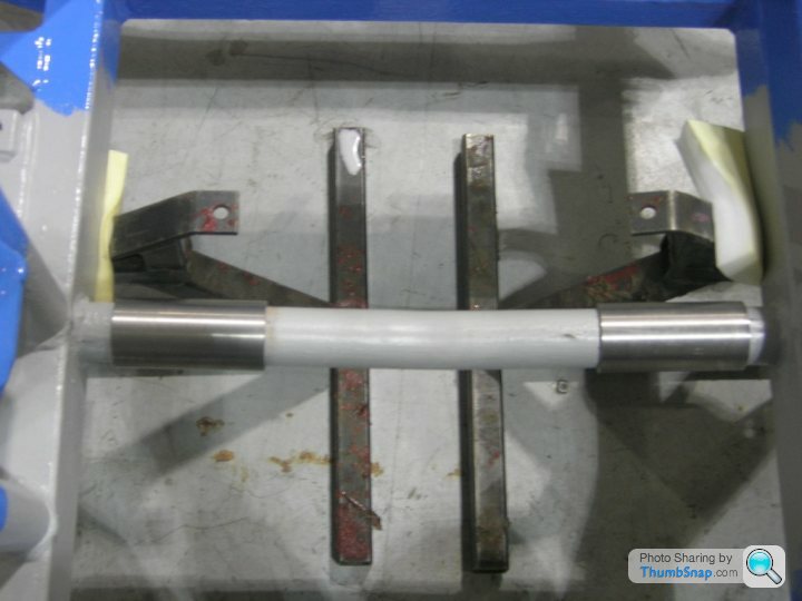
Here's my idea, using two metal sleeves which can be slid in and out of position to easily remove the crossmember. Each sleeve will be secured using 2-4 heavy duty M10 through bolts (not yet shown).
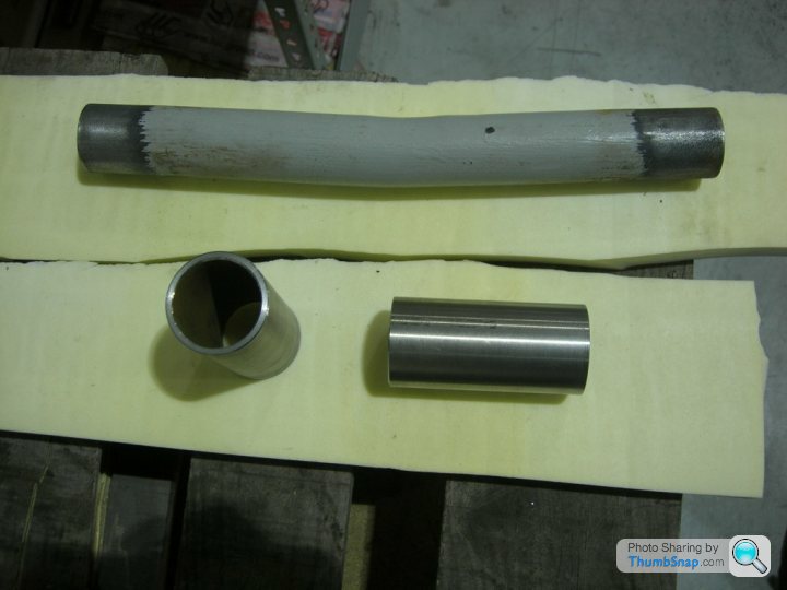
The metal sleeves were made from an outside diameter 50.8mm, 6.3mm wall thickness cold drawn seamless steel tube.
The outside diameter of the chassis crossmember is approx. 38mm, so this tube is a good fit.
The wall thickness of the tube was machined back to approx. 3.5mm.
Removed crossmember and sleeves
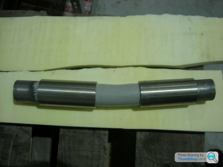
Sleeves slid over crossmember
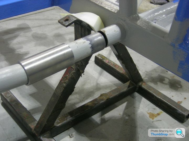
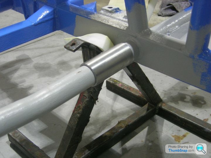
Sleeves slid into place
Any thoughts guys ?
Here's my idea, using two metal sleeves which can be slid in and out of position to easily remove the crossmember. Each sleeve will be secured using 2-4 heavy duty M10 through bolts (not yet shown).
The metal sleeves were made from an outside diameter 50.8mm, 6.3mm wall thickness cold drawn seamless steel tube.
The outside diameter of the chassis crossmember is approx. 38mm, so this tube is a good fit.
The wall thickness of the tube was machined back to approx. 3.5mm.
Removed crossmember and sleeves
Sleeves slid over crossmember
Sleeves slid into place
Any thoughts guys ?
I'm no engineer, but I think you need a continuous tube between the chassis rails, and the ends of the tube in tight contact with the rails, so the the stress can be transferred from one side to the other across the length of the cross-member.
How about cutting half the diameter off the stubs left of the chassis rails so as to form "saddles", then cut your new cross-member so that it is a tight fit between the chassis rails. Then locate the cross-member tube in the "saddles" you've made and clamp it in place with 'U' clamps. Probably not ideal either, but at least you will have metal to metal contact from one side to the other along the full length of the cross-member tube. You could cut just one stub first and see if you could wiggle the cross-member in that way.
How about cutting half the diameter off the stubs left of the chassis rails so as to form "saddles", then cut your new cross-member so that it is a tight fit between the chassis rails. Then locate the cross-member tube in the "saddles" you've made and clamp it in place with 'U' clamps. Probably not ideal either, but at least you will have metal to metal contact from one side to the other along the full length of the cross-member tube. You could cut just one stub first and see if you could wiggle the cross-member in that way.
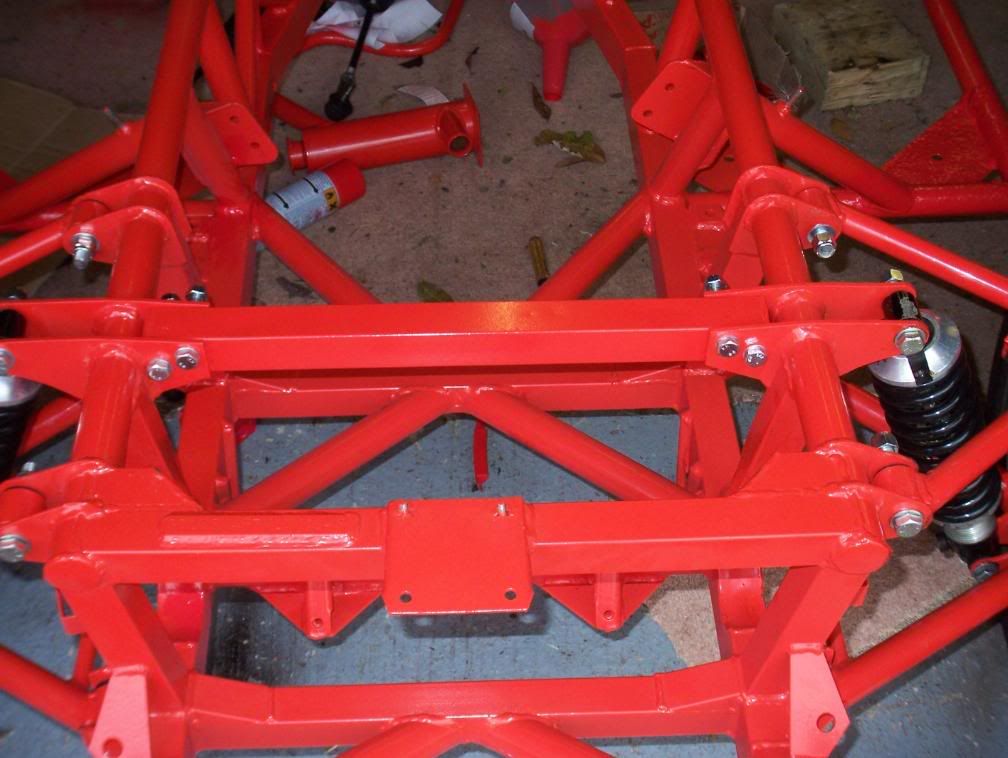
The V8S solution is below (sorry not a great angle)
Don't be afraid of getting a bit of welding done - generally not that expensive to get a mobile welder in to weld you a couple or tubes in. Strip the paint off first with a flap disc in an angle grinder.
Note also the removable cross-member - but then the V8S has a longer engine so I think you would get away without that.
I get where you were going with that - but with the chassis flex (that you get anyway with or without that tube) I don't think it would be long before that tube fell off - if it flies off at speed where's it going to end up?
However - I just thought of this - what diameter is that tube? Probably too small.
http://www.scaffolding-direct.co.uk/scaffold-clamp...
Just read your tube sizes but can't be arsed to edit the post - but at that price it might just be worth getting a couple to try?
However - I just thought of this - what diameter is that tube? Probably too small.
http://www.scaffolding-direct.co.uk/scaffold-clamp...
Just read your tube sizes but can't be arsed to edit the post - but at that price it might just be worth getting a couple to try?
Edited by Barkychoc on Wednesday 9th March 16:35
I confess I am not at all happy with modifications of this sort. That cross member is subject to stress under tension, compression, bending and torsion. Forgive me using the word but any 'amateur' mod may LOOK OK but unless it matches the stress resistance of the original it may not BE OK. But then, that is only the opinion of a mechanical engineer!
Thanks to everyone for the feedback.
This was just an idea from my side and all of the comments also really do confirm my initial thoughts regarding the "potential weakness" of this mod. So, it will be ceremonially binned
This afternoon, I ordered 2+2 lasercut flanges and these will be WELDED on to the ends of the crossmember tubes. I'll post a picture when it's all done and dusted.
Edited by TVRees on Wednesday 16th March 20:37
Gassing Station | S Series | Top of Page | What's New | My Stuff