Terry's tale. (S3 resto ++)
Discussion


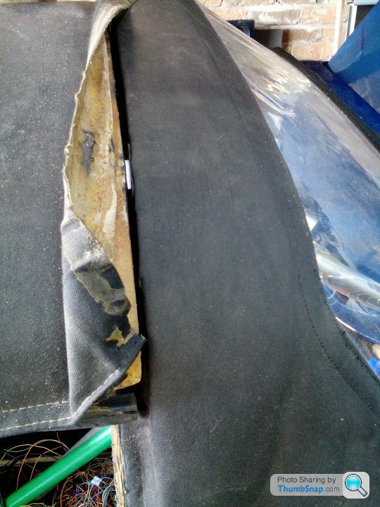
I've carried on working on with the targa roof panel box.
Rear bulkhead speaker holes dealt with, new carpet fitted with a flap when the box is empty.
New roof over-centre struts trial fitted, plus I have fitted new alloy tangs into the panels, holes cleaned then the new tangs glued in using body panel gunk. Its messy to work with (no different than working with strand glass). It goes off over night, and is slightly flexible, allowing any minor misalignment to be tolerated.
Note... I have deliberately left the old targa outer material flapping loose, so that when I (eventually) get around to doing the new hood and roof coverings, I will know where to cut & seam etc.
Edited by Blue 30 on Monday 5th August 22:31
Edited by Blue 30 on Monday 5th August 22:34
Oh, I forgot to mention that I have a fully operational braking system now.
I'm fibbing at little, as the handbrake lever is still in the boot somewhere !
But I'm happy that there are no fluid leaks.
One of the many 1/2 jobs done, that have to interlink with other 1/2 jobs is the resiting of the battery. The main charging/starting cables are in the boot now, as is a dedicated feed straight from the battery to the main dash loom 'live' which supplys the unswitched, the ignition switched, and the lighting circuits. I have fitted an inline power fuse, plus a kill switch in the boot on that supply line. I'll have to buy a battery soon so that I can get all wires cut and suitable battery clamps fitted etc. Which of course means, I'm getting dangerously close to cranking the engine... But I must remember to put engine oil in first !!!
One electrical query I do have, is....
My car is a 1990 S3, when I bought it, I was given one key as the 'fits all' key.
No issue with that, it locks the doors, it turns the ignition on and off.
However once I removed the door cards, each door contained a central locking solenoid. Both of these are the 2-wire version. So as there is no master 5-wire, it couldn't be operated from any key locking operation. Mmmm !
So (me thinks to myself) there must be a central locking module... Nothing found so far (4+ Years of ownership). Although I haven't done any serious detective work dedication in this persuance, following wiring etc.
My current assumption is, is that although solenoids & wiring exists, there was no working central locking.... I could be wrong.
So my question is... Did S3 cars have central locking ?
If so, was it originally key or fob operated ?
My car will have fob operated central locking, as I have bought a little black box that enables such.
T.
UPDATE... I've done a bit of searching around this forum, and may have the answer.
IE. Some cars didn't have central locking, and some did !
On some that didn't, they still might have the door actuators.
On cars that did have central locking, most had the CL incorporated within the fitted alarm system.
My car exhibits evidence of having a previously fitted alarm system.
IE. Cut/taped up wires on the indicator circuit, and interior light door switches.
So I guess on my car it was the alarm system that did the CL.
All long since gone of course, so saves me the job of stripping it out.
As I say, I have a new CL black box to fit anyway. My actuators & door locking does work under testing. So all good...
T.
Edited by Blue 30 on Tuesday 6th August 12:06
Edited by Blue 30 on Tuesday 6th August 12:07
Edited by Blue 30 on Tuesday 6th August 12:09
A bit more progress. Sorry about jumping about with jobs.
As they say, variety is the spice of life !
I have said numerous times, my project isn't just the drivetrain conversion, but also to get the rest of the car reliable & usable, as it was a poor example that I knowingly bought.
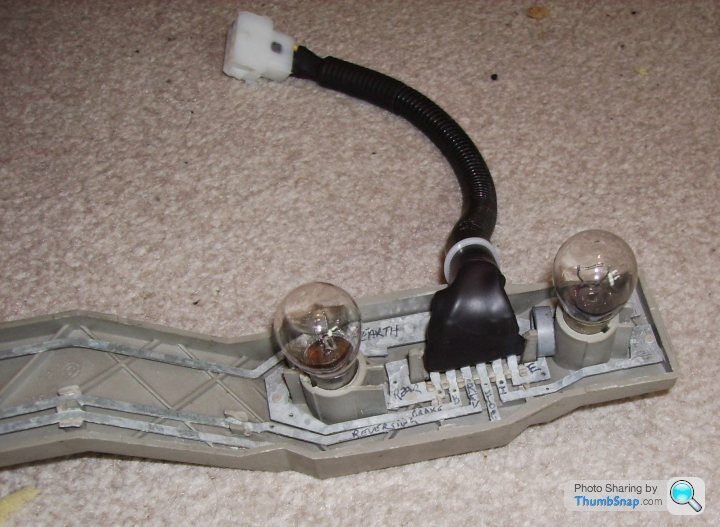
Rear lights, general inspection/revival.
The bulb housings dont appear too bad generally, but the wiring loom connectors are brown & ugh, so those will be cut off and different ones fitted (waiting on their arrival). See photo.
The connecting tabs within the housing also look suspect, so I am making some short tails up with individual small size push connectors. Photos to follow.

The number plate light was a different story. As once I peeled back the carpet. The bulb had apparently been glued in situ, with maybe, or maybe not, any electrical contact with the brass tabs, which were just floating about.
After about 30seconds of fleebay searching I found what might be a substitute. Led no less. The Tvr hole had been hacked out, so the new light unit had to go back in slightly out of square so that it seals. Anyway, unless you're on the floor you can't see it.... Very Tvr
Oh, I did come across something very closely situated to the number plate light (inside the boot) that apparently 'we' don't talk about !!!
I'll just say this, it helps in accessing your tools, if your battery goes flat !
Old & new number plate light units, and fitted.


Now press 'pause'.... Again... As our summer hols are imminent.
T
As they say, variety is the spice of life !
I have said numerous times, my project isn't just the drivetrain conversion, but also to get the rest of the car reliable & usable, as it was a poor example that I knowingly bought.
Rear lights, general inspection/revival.
The bulb housings dont appear too bad generally, but the wiring loom connectors are brown & ugh, so those will be cut off and different ones fitted (waiting on their arrival). See photo.
The connecting tabs within the housing also look suspect, so I am making some short tails up with individual small size push connectors. Photos to follow.
The number plate light was a different story. As once I peeled back the carpet. The bulb had apparently been glued in situ, with maybe, or maybe not, any electrical contact with the brass tabs, which were just floating about.
After about 30seconds of fleebay searching I found what might be a substitute. Led no less. The Tvr hole had been hacked out, so the new light unit had to go back in slightly out of square so that it seals. Anyway, unless you're on the floor you can't see it.... Very Tvr
Oh, I did come across something very closely situated to the number plate light (inside the boot) that apparently 'we' don't talk about !!!
I'll just say this, it helps in accessing your tools, if your battery goes flat !
Old & new number plate light units, and fitted.
Now press 'pause'.... Again... As our summer hols are imminent.
T
Edited by Blue 30 on Sunday 25th August 15:29

Blue 30 said:
I am making some short tails up with individual small size push connectors.
Good idea  ......... clicky dicky
I stuck with the original lamp which is TR7 but as they were sold as a pair I fitted a pair (hole filled and two new cut out) and used LED festoons..............

Edited by phillpot on Sunday 25th August 16:06
Thanks both, but I prefer the short tail option ( no jokes please... oh, go on then).
Thanks for the link Mike, yes that's what I'm doing in ref to the tails and plugs.
I bought my No plate led lights as a pair, but opted for using the existing single hole option (weight saving, better aero), and I have a spare maybe to use on inside of the rollover hoop.
T.
Thanks for the link Mike, yes that's what I'm doing in ref to the tails and plugs.
I bought my No plate led lights as a pair, but opted for using the existing single hole option (weight saving, better aero), and I have a spare maybe to use on inside of the rollover hoop.
T.
I copied Phillpot's idea using small spade connectors and multi-pin connector blocks and have't had an issue with the tail lights and indicators since. Top mod 

If you haven't already got one you'll find one of THESE invaluable. I can't find a listing for the one I bought for £30 but it has been worth every penny.
If you haven't already got one you'll find one of THESE invaluable. I can't find a listing for the one I bought for £30 but it has been worth every penny.
Yep, that's virtually what I'm doing too.
I have all of the tools and consumables, just waiting on the 6-way plug & sockets.
For everyone else's info....
5 out of the 6 pins in the housing are 12V inputs, the outer one is the common Neg (earth) input. So its important to keep that one isolated from the others.
If any of others touch each other, you will just get funny lighting pattern(s).
So you might as well sleeve those from each other too.
I will also be insitu testing mine from the disconnected column stalk plug too.
That's before I couple it all back into the stalks and loom wiring.
Thanks for all input.
T.
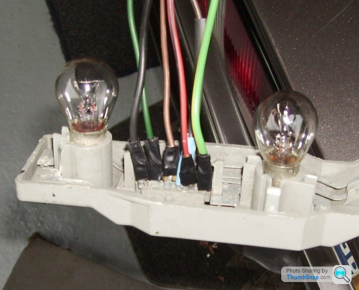

Terminals at the lamps pins are not needed If you are fitting and wiring multi-plugs with fly leads. The reason being that if the lamps do ever need disconnecting for removal or testing purposes, this is achieved by disconnecting them at their fly leads multi-plugs
When modifying a lamps wiring as above, the original lamps plugs become redundant, this allows the soldering and sealing of cables directly to the lamps male pins or to the lamps internal conductor bars
Using terminals to connect the fly leads to the lamps male pins is not a very good method
I have never witnessed any skilled automotive electricians using terminals to connect fly leads to the lamps pins, they have always soldered them
Less joints for the rear lamps in the boot space = Less chance of volt-drops, this is the reason why
Don't get me wrong, anyone can do what they want with their cars electrics. The thing is professionals do give much more thought about best methods used
Dear Mr P - are you up for a good humored challenge? If you are then can I suggest you get yourself a rear lamp holder ( LIKE THIS) and show us all how you solder the wires onto the terminals.
I'm sure we can all lean from a practical demonstration of your professional soldering skills
I'm sure we can all lean from a practical demonstration of your professional soldering skills
When the original flying lead connector became too dirty/corroded and I found it difficult to lay any solder on the galvanised prongs I then just used individual 2.8mm female crimp connectors in the wires along with heatshrink sleeving. No problems in the last 5 years.
If laying solder could be successful I'd rather do that and fit a new flying lead connector pair similar to those I've used on the dashboard.
If laying solder could be successful I'd rather do that and fit a new flying lead connector pair similar to those I've used on the dashboard.
I agree with the principle of, less joints = less fault liability.
However once I looked at the Ford quality (now there's a contradiction) of the lamp housing, and how the flat plate wiring is held I place by dabs of melted plastic, especially close to the input pins. It is pretty obvious what will happen if long duration heat is applied, to solder wire tails onto the pins.
And therefore for that reason alone I opted for push connectors.
My intention is to replace all rear filament lamps, with Led ones.
Thus reducing current flow, and the potential of any associated heat at the friction joints.
T.
It's all about the soldering method used
I have already mentioned that fly leads can be soldered to the conductor bars
Anyway, I'll post the following as others may benefit from it in the future
The OP Blue 30 has mentioned that the plastic that holds the bars will melt when soldering to them, the best way of overcoming the problem of heat conducting along the bars is to apply the ends of big flat screwdrivers to points along the bar a little distance away from the area that's being soldered to, pointed pliers and tweezers can also be used, heat-sinks work wonders
The thing is, as long as the area is cleaned up properly, a biggish soldering iron with a narrow tip will quickly give the required soldering temperature and the plastic doesn't often melt away even without a heat-sink
The bars can also be clamped in place so they can't move when heat is applied to them
The job is much easier than it looks, if soldering at the male pins, cardboard can be used in-between them so as to stop the chances of solder running across them
Pins 2 and 4 can be cut off leaving more room to solder to pins 1,3 & 5
Pins 2 and 4 bars can be connected to at points along them inside the plate
The other option is to modify the plates by cutting out the holders and fitting new bulb holders
Edited by Penelope Stopit on Tuesday 27th August 15:53
Penelope Stopit said:
It's all about the soldering method used...........
So please show how you successfully solder to these pins. A practical example would be so much more helpful than reams of theoretical text.My challenge is to show us how you do it rather then tell us how we should do it. All you have to do is get hold of a scrap lamp holder, solder wires to the pins and post up a photo.
We really would appreciate knowing how to do this.
Personally I'm bored with this now...
I go into my garage, find wire, connectors, crimping tool, shrink wrap.
Strip wire, crimp on connectors, cover with sleeving, clean pins, fit connectors.
More sleeving over all wires.... Close garage, wash hands, have dinner/tea/etc.
Still waiting for new multi plugs to arrive... So doing sumat else tomorrow.
T.
Gassing Station | S Series | Top of Page | What's New | My Stuff