Pektron Steering Module
Discussion


adam quantrill said:
Do you mean you turn it over from cold and it doesn't start for about 10 seconds?
But if you turn it over for 3 seconds, leave it for 5 seconds, then turn over again, it fires immediately?
no, the pump is not priming at all, so I to keep turning it over for about 60 seconds or more till it catch,then it tick over slow till it picks up a bit ,But if you turn it over for 3 seconds, leave it for 5 seconds, then turn over again, it fires immediately?
nwarner said:
Hi
Does anyone know of a source of one of these or a work around so I can use the Wedge? I was having starting issues and traced the fault to the steering module and as I couldn't find a replacement anywhere I sent it off to be repaired but unfortunately it was lost in the post so now I can't start it at all :-(
Nige
hi, what starting issues was you getting then? was the same as my one,
superwedge said:
hi, I been having trouble starting as well,the pump would buzz for a few seconds when I turn the key to start, but that has stop and it takes some turning over before it does, so this may be the cause then, if you got one spare kkson, I buy it off you if up for selling it cheers,

I recall that someone posted in the past stating that the pump didn't prime with ignition on, there is only one way the pump could possibly prime with ignition on and that would be from a ECU pin 20 positive output when switching the ignition on, I thought ECU pin 20 received an input from the airflow meter contact......I could be wrong but.....
Take a look at the diagram I've drawn for the Pektron circuit and you will see that the fuel pump relay is operated when turning the key to the crank position and also when the airflow meter contact switches in
If you are 100% sure that your pump primed when switching the ignition on, there is the possibility that a incorrectly wired Pektron was causing it or a relay fitted in the wrong place, a faulty diode inside the Pektron could also cause this
You could do with someone verifying that an identical cars fuel pump does or doesn't prime when the ignition is turned on
Edited by Penelope Stopit on Tuesday 22 January 21:30
I've two Wedges. My 350i fuel pump only kicks in when the engine is cranked or if the ignition is in the on position and the air flow meter flap is manually opened (finger in the orifice missus). On my 390SE however generally the pump runs as soon as the ignition is in the on position. The AFM however is a larger unit off a Jaguar so not sure if this is the reason. Either way both engines run fine the moment the key is turned and engine cranked.
KKson said:
I've two Wedges. My 350i fuel pump only kicks in when the engine is cranked or if the ignition is in the on position and the air flow meter flap is manually opened (finger in the orifice missus). On my 390SE however generally the pump runs as soon as the ignition is in the on position. The AFM however is a larger unit off a Jaguar so not sure if this is the reason. Either way both engines run fine the moment the key is turned and engine cranked.
This will surely help Superwedge, perhaps others will post how their circuit operates, the problem is the cars vary so much and posters don't often mention what model/enginesuperwedge said:
hi, what starting issues was you getting then? was the same as my one
It wouldn't start at all as the fuel pump wasn't getting any power to it when I opened the flap in the AFM. I found that there was power going to the Starter Relay but there was no power coming out of it.Steve_D said:
Penelope Stopit said:
Steve
Would we be correct in stating that the Pektron could be thrown away and replaced with 2 diodes.....I think this is a goer....What do you think?
See https://www.pistonheads.com/gassing/topic.asp?h=0&... Pasted here -
honestjohntoo said:
Ian350 said:
I think this is playing up --- It is the red relay in the corner of the fuse board. It seems to control the fuel pump - when it feels like it.
It may help you to understand how the steering module does its work.Introduction and Location
The Rover SD1 Efi Steering Module activates the Main (Efi) and Fuel Pump relays in a safe sequence and routes power to other key components.
Mounted on the smaller bracket with the relays behind the passenger glove box, it usually has a red plastic cover.
The Main and Fuel Pump Relays are intimately involved with the purpose and function of the Steering Module.
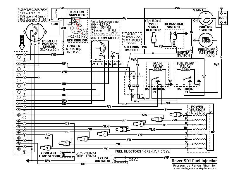
Circuit Diagram
This shows component connections together with their identity in the adjacent list. The Efi Steering Module derives its name from its function of routing power according the mode of operation.
Component Identity
SM Steering Module
MR Main relay
FPR Fuel Pump relay
BATT Battery
IS Ignition switch
FP Fuel Pump
EAV Extra air valve
AFM Air flow meter

Operation
The white (W) wire from the ignition switch supplies power through the right hand diode in the Steering Module (terminals 4 to 1) seen above. From there it connects to terminal 85 of the Main relay, through the relay windings to earth via terminal 86 to close the contacts when energised.
Power is now available directly from the battery via terminals 30/51 and 87 to the air flow meter (Fuel Pump contacts), Pin 10 of the ECU and to the Power Resistors which connect to the fuel injectors. However, current can only energise the injectors when the ECU completes their circuits to earth with appropriately timed injection pulses.
The Fuel Pump relay is also activated through the Steering Module but in two different modes. Initially, in engine cranking mode, power is available to the Steering Module terminal 3 via the white/red (WR) wire from the ignition switch cranking circuit. Then, as the engine starts, in engine running mode, power reaches terminal 2 via the blue/purple (UP) wire coming from the now closed Fuel Pump contacts inside the Air Flow Meter, also connected to Pin 20 of the ECU.
In either mode, current passes from the Steering Module via the respective diodes at terminal 5 to the Fuel Pump relay terminal 85, through the relay windings to earth. The closed relay contacts operate both the Fuel Pump and the Extra Air Valve with power drawn from the ignition switch.
These two diodes, by their nature of preventing current from flowing in the reverse direction, ensure that operating current from terminal 3 cannot pass to terminal 2 and vice versa.
In summary, the Fuel Pump is initially energised in the cranking mode but as soon as the engine draws air through the air flow meter its internal Fuel Pump contacts close, completing the alternative circuit to keep the Fuel Pump energised until either the ignition is switched off or the engine stalls, the Air Flow Meter flap closes, thus opening its internal Fuel Pump contacts.
The above operational description is limited to the immediate circuitry of the subject components but a complete Rover SD1 Efi circuit diagram may also help:
Reliabilty and Replacement
Components in the Rover SD1 Efi System have varying degrees of reliability but the Steering Module has proved, over time, to be a very robust item not prone to chronic failure. One hears anecdotal evidence of failure but they seem to coincide with injudicious poking around with meter probes elsewhere in the system that cause short circuits capable of damaging the internal diodes.
The diodes, type 1N4006, are straight forward items readily available from semiconductor vendors at low cost and can be easily tested/replaced. However the fourth component in the module is an unusual fusible resistor, rated at 2.7 Ohms. Because it is an ECU protection and safety item it must be replaced "like for like". Replacements are inexpensive but will be harder to find.
To that end, and due to low failure rate, one often sees used Modules and Relays at Club Spares Days. Also SD1 Ebayers and Land/Range Rover S/H spares suppliers would readily provide them.
Conclusions
Because of its strange name and relative inaccessibility, the Steering Module and the associated relays have a reputation of unwarranted mysticism, whereas, in fact, it simply makes sure that the Main and Fuel Pump relays operate correctly and safely during the cranking and running modes.
There is loads more about the Flapper Efi system here
Penelope Stopit said:
Would we be correct in stating that the Pektron could be thrown away and replaced with 2 diodes.....I think this is a goer....What do you think?
While this may work in theory, don't forget that the car has undergone some sort of type approval back in the day.I think you are both starting to hit on failure modes of the surrounding circuitry that the third diode is there to protect against, but there may be others that you haven't yet discovered, that are safety and type approval related. Unless we have the musings of the original designer to help it might be premature to alter the circuit.
After all, given the meagre the cost of a few diodes there's no financial incentive to chop them out.
Given the need for these I am getting my son to crank up his CAD package and we'll get some 3-D printed (in red plastic of course).
The internal diodes will be uprated versions of the standard silicon diodes, so it should be bulletproof.
I am aiming for a target price of a tenner plus P+P. Watch this space!
Let me know if you're interested.
Sales will be stricly on the basis of "diagnostic use" only, so you fit it in your garage, and if it fixes the problem, you know it's your Pektron that's giving up. If you run it on the road or track, it's at your own risk.
As promised, here's the first prototype (original on the right).
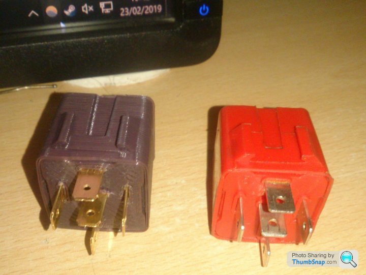
We'll be doing the first batch with red substrate of course. Different to the original is a textured feel to the sides due to the 3D printing process. I will keep this as it adds a "grippy" feel to the sides.
The internal diodes will be uprated versions of the standard silicon diodes, so it should be bulletproof.
I am aiming for a target price of a tenner plus P+P. Watch this space!
Let me know if you're interested.
Sales will be stricly on the basis of "diagnostic use" only, so you fit it in your garage, and if it fixes the problem, you know it's your Pektron that's giving up. If you run it on the road or track, it's at your own risk.
As promised, here's the first prototype (original on the right).
We'll be doing the first batch with red substrate of course. Different to the original is a textured feel to the sides due to the 3D printing process. I will keep this as it adds a "grippy" feel to the sides.
Edited by adam quantrill on Saturday 23 February 20:27
adam quantrill said:
Penelope Stopit said:
Would we be correct in stating that the Pektron could be thrown away and replaced with 2 diodes.....I think this is a goer....What do you think?
While this may work in theory, don't forget that the car has undergone some sort of type approval back in the day.I think you are both starting to hit on failure modes of the surrounding circuitry that the third diode is there to protect against, but there may be others that you haven't yet discovered, that are safety and type approval related. Unless we have the musings of the original designer to help it might be premature to alter the circuit.
After all, given the meagre the cost of a few diodes there's no financial incentive to chop them out.
adam quantrill said:
Given the need for these I am getting my son to crank up his CAD package and we'll get some 3-D printed (in red plastic of course).
The internal diodes will be uprated versions of the standard silicon diodes, so it should be bulletproof.
I am aiming for a target price of a tenner plus P+P. Watch this space!
Let me know if you're interested.
Don't forget Type Approval https://en.wikipedia.org/wiki/Type_approvalThe internal diodes will be uprated versions of the standard silicon diodes, so it should be bulletproof.
I am aiming for a target price of a tenner plus P+P. Watch this space!
Let me know if you're interested.
Don't forget Public Liability Insurance https://www.hiscox.co.uk/business-insurance/public...
You have mentioned safety and type approval in your above post
adam quantrill said:
While this may work in theory, don't forget that the car has undergone some sort of type approval back in the day.
I think you are both starting to hit on failure modes of the surrounding circuitry that the third diode is there to protect against, but there may be others that you haven't yet discovered, that are safety and type approval related. Unless we have the musings of the original designer to help it might be premature to alter the circuit.
After all, given the meagre the cost of a few diodes there's no financial incentive to chop them out.
The 3rd diode in the Pektron circuit is doing nothing more than what I've already posted aboveI think you are both starting to hit on failure modes of the surrounding circuitry that the third diode is there to protect against, but there may be others that you haven't yet discovered, that are safety and type approval related. Unless we have the musings of the original designer to help it might be premature to alter the circuit.
After all, given the meagre the cost of a few diodes there's no financial incentive to chop them out.
You have posted but there may be others that you haven't yet discovered
There is nothing else to be discovered about that 3rd diode
Are you aware that the majority of relays don't have a diode in series with the winding to protect against the chance of another relay filling with water, corroding and supplying a positive or negative to them
I have posted a method that people can use to get their vehicle safely back up and running
Are you out of your depth? Some of your comments suggest that you are
Very quietly... it is the red lump on the relay board, it energises the fuel pump when starting or running the engine, and in the cases where you have an intertia cutoff switch also has a third diode that prevents a fault in the main relay from also energising the fuel pump. The latter fault would otherwise go unnoticed until you crashed the car (heaven forbid!).
Penelope Stopit said:
adam quantrill said:
While this may work in theory, don't forget that the car has undergone some sort of type approval back in the day.
I think you are both starting to hit on failure modes of the surrounding circuitry that the third diode is there to protect against, but there may be others that you haven't yet discovered, that are safety and type approval related. Unless we have the musings of the original designer to help it might be premature to alter the circuit.
After all, given the meagre the cost of a few diodes there's no financial incentive to chop them out.
The 3rd diode in the Pektron circuit is doing nothing more than what I've already posted aboveI think you are both starting to hit on failure modes of the surrounding circuitry that the third diode is there to protect against, but there may be others that you haven't yet discovered, that are safety and type approval related. Unless we have the musings of the original designer to help it might be premature to alter the circuit.
After all, given the meagre the cost of a few diodes there's no financial incentive to chop them out.
You have posted but there may be others that you haven't yet discovered
There is nothing else to be discovered about that 3rd diode
Are you aware that the majority of relays don't have a diode in series with the winding to protect against the chance of another relay filling with water, corroding and supplying a positive or negative to them
I have posted a method that people can use to get their vehicle safely back up and running
Are you out of your depth? Some of your comments suggest that you are
Penelope Stopit said:
I know what you mean, that 3rd diode can do nothing other than protect the ignition circuit from being supplied a positive from the injection relay should it fill with water/corrosion, I also question the use of a resistor in the Pektron, in the below information it is mentioned that the fusible resistor protects the ECU, in looking at the diagram it can be seen that ECU Pin 20 connects to the positive output from the airflow meter flapper contact and the resistor is not in this part of the circuit. The below information about operation doesn't mention that the ECU primes the fuel pump at the initial ignition on stage and other posters have mentioned that there is no initial fuel pump priming. I think that the resistor will semi protect an ECU that is programmed to prime the fuel pump at the ignition on stage and the function is possibly used for certain models of TVR or other manufacturers vehicles such as Rover
adam quantrill said:
Very quietly... it is the red lump on the relay board, it energises the fuel pump when starting or running the engine, and in the cases where you have an intertia cutoff switch also has a third diode that prevents a fault in the main relay from also energising the fuel pump. The latter fault would otherwise go unnoticed until you crashed the car (heaven forbid!).
The thing is..........If the main injection relay suffered enough corrosion to supply a voltage high enough to hold the fuel pump relay in (8-9volts at a guess as they differ), it would be in such a state that it would no longer function due to its armature being siezed and its contacts in a mess and not conducting, this means that the engine wouldn't run but the 3rd diode would still stop the fuel pump from running when it shouldn't beOnly now has it become apparent to me that the 3rd diode is adding some idiot proofing to the circuit and also protecting the circuit in the case of water in the fusebox area from causing tracking
There is something else, If there was an electrical short circuit in the wiring harness due to a burnt loom the 3rd diode will protect the fuel pump circuit from being energised. Even though the circuit is protected from shorts across wiring by the 3rd diode, it doesn't prevent a short directly from a positive supply to the fuel pump cable
Gassing Station | Wedges | Top of Page | What's New | My Stuff