Sparking problem
Discussion


Ok so I accept I don't understand basic electronics or what goes on in a coil...
This mornings test.
Took coil off car so totally standalone.
Connected coil up to different battery plus to plus, minus to minus, and measured voltage between positive terminal on coil and negative terminal on Battery.
Initial voltage of battery alone was 12.2 volts, measured voltage after connection 11.2 volts.
Now I know my little volt measuring device cannot be totally accurate and measurements change depending on how the needle point contacts make contact with dirty greasy terminals, but test can be reproduced more than once.
Holding station while measuring I may be seeing the voltage drop gradually even further but I cannot guarantee that test and I have no wish to burn out another coil.
So Penelope it looks like O Mage has a point, but I'm dammned if I can understand what's going on.
More importantly The OP needs to find his problem elsewhere as I think this drop when earthing coil is standard. (Homage to OMage?)
I await enlightenment.
So I guess we haven't sorted Big Fish's problem yet...
Moving on from the coil voltage saga if we can...
I've had similar problems in the past and replaced coil dizzie plugs leads etc. From my experience, I found it difficult to set the static timing when using electronic ignition. I had to guess where the star ring point/nipple needed to be in relation to the sensor - you can just see this with the cap off without dismantling further.
I also struggled with TDC finding that my TDC is about 3 degrees after.
I also went back and checked the valve timing was correct (paranoid)
I also managed to get the dizzie 180 degrees out of sync despite being absolutely sure I had left the engine on TDC no 1. That doesn't help at all
I did one other thing which may be a red herring... the new dizzie came with a new red rotor arm, I compared this with the old black one, and found a smidge of difference. So while the engine seems to be working ok with the black one, it is a new rebuild so has only had a few starts and tickovers and hasn't even seen a road yet. The reason I changed it was on the new red one I found the spark marks on the very Left hand end of the brass rotor which should line up with each dizzie terminal. The black one should shift the spark location a mm or two back to the middle of the brass bit. But beware another red herring!
I also FIRMLY located each of the HT leads to the dizzie and the plugs and the king lead. Also mounted the coil on the engine (temporarily?) and was able to use a shorter king lead.
However my problems aren't just sparks and timing as I have had to take the original EFI stuff off, also throw away the Weber carb and manifold which it came with, and put on a pair of SU's which I understand better how that works. For me the lucas 4cu and flapper system has too many electro mechanical areas that can fail to be able to diagnose a starting/idling issue.
So I hope the OP will come back and say where he is with his problem (geographically and statuswise). And if he is local to anyone perhaps two heads will be better than one. I'm in West Berkshire, isolating but happy to help if I can.
Nickl911 said:
Ok so I accept I don't understand basic electronics or what goes on in a coil...
This mornings test.
Took coil off car so totally standalone.
Connected coil up to different battery plus to plus, minus to minus, and measured voltage between positive terminal on coil and negative terminal on Battery.
Initial voltage of battery alone was 12.2 volts, measured voltage after connection 11.2 volts.
Now I know my little volt measuring device cannot be totally accurate and measurements change depending on how the needle point contacts make contact with dirty greasy terminals, but test can be reproduced more than once.
Holding station while measuring I may be seeing the voltage drop gradually even further but I cannot guarantee that test and I have no wish to burn out another coil.
So Penelope it looks like O Mage has a point, but I'm dammned if I can understand what's going on.
More importantly The OP needs to find his problem elsewhere as I think this drop when earthing coil is standard. (Homage to OMage?)
I await enlightenment.
Well done with the tests and thank you for the acknowledgement there is one more test you can do just to make sure all is as it should be in this area and can maybe shed some light on where its going for you but it will also open up a new can of worms in this thread. I would like to hear if the op has it sorted yet. Im guessing he's got a dodgy amp again.This mornings test.
Took coil off car so totally standalone.
Connected coil up to different battery plus to plus, minus to minus, and measured voltage between positive terminal on coil and negative terminal on Battery.
Initial voltage of battery alone was 12.2 volts, measured voltage after connection 11.2 volts.
Now I know my little volt measuring device cannot be totally accurate and measurements change depending on how the needle point contacts make contact with dirty greasy terminals, but test can be reproduced more than once.
Holding station while measuring I may be seeing the voltage drop gradually even further but I cannot guarantee that test and I have no wish to burn out another coil.
So Penelope it looks like O Mage has a point, but I'm dammned if I can understand what's going on.
More importantly The OP needs to find his problem elsewhere as I think this drop when earthing coil is standard. (Homage to OMage?)
I await enlightenment.
Nickl911 said:
Ok so I accept I don't understand basic electronics or what goes on in a coil...
This mornings test.
Took coil off car so totally standalone.
Connected coil up to different battery plus to plus, minus to minus, and measured voltage between positive terminal on coil and negative terminal on Battery.
Initial voltage of battery alone was 12.2 volts, measured voltage after connection 11.2 volts.
Now I know my little volt measuring device cannot be totally accurate and measurements change depending on how the needle point contacts make contact with dirty greasy terminals, but test can be reproduced more than once.
Holding station while measuring I may be seeing the voltage drop gradually even further but I cannot guarantee that test and I have no wish to burn out another coil.
So Penelope it looks like O Mage has a point, but I'm dammned if I can understand what's going on.
More importantly The OP needs to find his problem elsewhere as I think this drop when earthing coil is standard. (Homage to OMage?)
I await enlightenment.
OoopsThis mornings test.
Took coil off car so totally standalone.
Connected coil up to different battery plus to plus, minus to minus, and measured voltage between positive terminal on coil and negative terminal on Battery.
Initial voltage of battery alone was 12.2 volts, measured voltage after connection 11.2 volts.
Now I know my little volt measuring device cannot be totally accurate and measurements change depending on how the needle point contacts make contact with dirty greasy terminals, but test can be reproduced more than once.
Holding station while measuring I may be seeing the voltage drop gradually even further but I cannot guarantee that test and I have no wish to burn out another coil.
So Penelope it looks like O Mage has a point, but I'm dammned if I can understand what's going on.
More importantly The OP needs to find his problem elsewhere as I think this drop when earthing coil is standard. (Homage to OMage?)
I await enlightenment.
The coil charging time increases on account of the voltage supply being too low
It is essential to use the vehicle ignition coil as the load for the following test and ensure it is rated at 12 volts
The correct method for testing a 12 volt ignition coil supply voltage is.....
Ensure battery is fully charged
Disconnect all cables that are connected to the coil negative terminal
Using a known good jumper cable with a current rating of 15 amps or more, connect coil negative to battery negative
Switch ignition on
Measure battery voltage at its lugs
Measure coil positive supply voltage by connecting voltmeter between coil positive and coil negative
The coil positive supply voltage should be within fractions of a volt of the measured battery voltage
If the coil supply voltage is found to have a very high volt-drop (0.5 volts volt-drop is on the high side) there is a problem that needs rectifying
The above information was found inside the brain of Penelope Stopit
All the above information is readily available at many reputable automotive electrical websites for anyone to read through should they doubt the accuracy of the above test procedure
Penelope Stopit said:
Should 1000 posters all post here that the measured voltage at the 12 volt ignition coil supply was 10.5 volts when under coil load.......
The above would prove that there were 1000 TVR's known to have ignition coil supply problems
It's a fact
Unfortunately "Penelope" I'm not sure I agree with this and to be honest I'm not getting into any form of argument. So both of my Wedges have around 9 volts at the coil with ignition on but engine not running. Whether that's right or wrong they both run without issue and they generate great big fat sparks. The 390SE had a VERY expensive rolling road session the other year and a full health check at the hands of probably the UK's leading expert in Rover and flapper EFi systems. The tests included voltage measurements, ECU measurements, timing etc etc. The above would prove that there were 1000 TVR's known to have ignition coil supply problems
It's a fact
I'm not an electrical expert but I think the original issues the OP is having may well have nothing to do with the coil voltage. My SEAC is also due for a full health check on the 3rd July at the hands of the same specialist (Mark Adams and Shropshire Automotive) so I will ask him the question as to what he considers the coil voltages should be.
KKson said:
Unfortunately "Penelope" I'm not sure I agree with this and to be honest I'm not getting into any form of argument. So both of my Wedges have around 9 volts at the coil with ignition on but engine not running. Whether that's right or wrong they both run without issue and they generate great big fat sparks. The 390SE had a VERY expensive rolling road session the other year and a full health check at the hands of probably the UK's leading expert in Rover and flapper EFi systems. The tests included voltage measurements, ECU measurements, timing etc etc.
I'm not an electrical expert but I think the original issues the OP is having may well have nothing to do with the coil voltage. My SEAC is also due for a full health check on the 3rd July at the hands of the same specialist (Mark Adams and Shropshire Automotive) so I will ask him the question as to what he considers the coil voltages should be.
Im sure if you ask him he will say 12v, this phenomena if we can call it that and others i may add tend to go unnoticed even by the best. If you show it him he will take a minuet and then realize he has never thought about it before. Nikola tesla invented the device and these are automotive tesla coils /slightly different. The output is even more interesting because it will jump to negative as it does into the block and it will jump to positive aswell. And i would say he wont know that either. I dont think there is an ideal voltage for that test and they may all be different.I'm not an electrical expert but I think the original issues the OP is having may well have nothing to do with the coil voltage. My SEAC is also due for a full health check on the 3rd July at the hands of the same specialist (Mark Adams and Shropshire Automotive) so I will ask him the question as to what he considers the coil voltages should be.
All well and good, but it doesn't matter. I have 9 volts at both coils and the EFi runs great, emissions are spot on and the cars go like stink. The original poster didn't have the luxury of a car that behaved. I'm therefore not convinced the slightly lower coil voltage has anything to do with his issue.......
I imagine Bigfish has now lost the will to live...... and this post is going no where.
I imagine Bigfish has now lost the will to live...... and this post is going no where.
KKson said:
Penelope Stopit said:
Should 1000 posters all post here that the measured voltage at the 12 volt ignition coil supply was 10.5 volts when under coil load.......
The above would prove that there were 1000 TVR's known to have ignition coil supply problems
It's a fact
Unfortunately "Penelope" I'm not sure I agree with this and to be honest I'm not getting into any form of argument. So both of my Wedges have around 9 volts at the coil with ignition on but engine not running. Whether that's right or wrong they both run without issue and they generate great big fat sparks. The 390SE had a VERY expensive rolling road session the other year and a full health check at the hands of probably the UK's leading expert in Rover and flapper EFi systems. The tests included voltage measurements, ECU measurements, timing etc etc. The above would prove that there were 1000 TVR's known to have ignition coil supply problems
It's a fact
I'm not an electrical expert but I think the original issues the OP is having may well have nothing to do with the coil voltage. My SEAC is also due for a full health check on the 3rd July at the hands of the same specialist (Mark Adams and Shropshire Automotive) so I will ask him the question as to what he considers the coil voltages should be.
There is nothing to argue about, have posted up how to test an ignition coil circuit supply for a 12 volt ignition coil system.....meaning no ballast resistor
Some posters to this topic have commented that a 12 volt coils ignition supply can be expected to drop by 2 volts when the negative side of the coil is earthed.............this is not the case, it doesn't drop by more than fractions of a volt if in good order
Not one of the posters have explained how the voltage could possibly drop by 2 volts...........because it can't, if in good order
See below post for 9 volt ignition circuits
Penelope Stopit said:
No problem KKson
There is nothing to argue about, have posted up how to test an ignition coil circuit supply for a 12 volt ignition coil system.....meaning no ballast resistor
Some posters to this topic have commented that a 12 volt coils ignition supply can be expected to drop by 2 volts when the negative side of the coil is earthed.............this is not the case, it doesn't drop by more than fractions of a volt if in good order
Not one of the posters have explained how the voltage could possibly drop by 2 volts...........because it can't, if in good order
See below post for 9 volt ignition circuits
Volts disappear and heat appears shall we just call it a magic box. The secondary in these automotive tesla coils is connected to the primary at the mid point of the primary inside the casing of the device you are testing. Does that help.?There is nothing to argue about, have posted up how to test an ignition coil circuit supply for a 12 volt ignition coil system.....meaning no ballast resistor
Some posters to this topic have commented that a 12 volt coils ignition supply can be expected to drop by 2 volts when the negative side of the coil is earthed.............this is not the case, it doesn't drop by more than fractions of a volt if in good order
Not one of the posters have explained how the voltage could possibly drop by 2 volts...........because it can't, if in good order
See below post for 9 volt ignition circuits
O mage said:
Volts disappear and heat appears shall we just call it a magic box. The secondary in these automotive tesla coils is connected to the primary at the mid point of the primary inside the casing of the device you are testing. Does that help.?
Does that help Bigfish and his original issue? 
KKson said:
Does that help Bigfish and his original issue?
No, i know what you mean but the op needs to understand that the reading is around standard when testing this circuit And that the car will probably start with that reading as it's been noted on several similar running vehicles or we are wasting his time.KKson
I think you have proven that your vehicles are running on 9 volt coils with ballast resistor
Below is the test for a 9 volt ignition coil circuit and apart form working with a lower supply voltage it doesn't differ from a 12 volt circuit test apart from a crank voltage test being added
When earthing a 9 volt coil to test the supply voltage it is important to carry out the test within 15 seconds of switching the ignition on, this ensures the ballast resistor cant possibly overheat, allow a minute for the resistor to cool between tests
It is essential to use the vehicle ignition coil as the load for the following test and ensure it is rated at 9 volts
The correct method for testing a 9 volt ignition coil supply voltage is.....
Ensure battery is fully charged
Disconnect all cables that are connected to the coil negative terminal
Using a known good jumper cable with a current rating of 15 amps or more, connect coil negative to battery negative
Switch ignition on
Operate the starter motor and measure the battery voltage while it's cranking
Operate the starter motor and measure the coil positive supply voltage by connecting voltmeter between coil positive and coil negative
The coil supply voltage while cranking should be anything from 0.00 volts (wishful thinking) to 1 volt less than the measured battery cranking voltage if a starter motor solenoid ballast resistor bypass terminal is being used to supply the coil during cranking
The above 0.00 to 1 volt volt-drop is caused by the volt-drop along the starter motor battery cable during cranking and burnt solenoid contacts
Example below
Battery voltage while cranking is found to be 10 volts
The coil supply voltage from the starter motor solenoid bypass terminal is found to be 9 volts (starter cable and contacts volt-drop)
The vehicles has a 9 volt coil that is being supplied 9 volts during cranking
Lovely, just what the coil needed to produce a full voltage healthy spark at the spark plugs
The above 0.00 to 1 volt volt-drop can be reduced by wiring a relay to switch battery voltage to the coil during cranking rather than starter solenoid voltage
That's the cranking voltage test completed onwards and downwards to the ballast supply voltage
Ensure battery is fully charged
Disconnect all cables that are connected to the coil negative terminal
Using a known good jumper cable with a current rating of 15 amps or more, connect coil negative to battery negative
Switch ignition on
Measure battery voltage at its lugs to ensure voltage is not dropping below 12 volts
Measure coil positive supply voltage by connecting voltmeter between coil positive and coil negative
The coil positive supply voltage should be 9 volts +/- fractions of a volt and this voltage does depend upon what the battery voltage is at the time of measuring
Lovely, the ignition is switched on and there is very close to a 9 volts supply at a 9 volt coil
Same again for 6 volt ignition coil circuits, calculating to the lower supply voltage
Now if we go back to the OP's problem
A vehicle with a good fully charged battery and the correct ballast resistor/coil voltage combination
It is not possible to see 10.5 volts at the ignition coil supply when there is 12.5 volts measured at the battery unless there is something wrong
Whatever the coil or ballast/coil combination......
12 volts no ballast
9 volts
6 volts
10.5 volts = problem and needs to be sorted before further testing as there is no possible way 10.5 volts should be seen if all is well
There is always the possibility of volt-drops or incorrect coils and or resistors/resistor cables
O mage said:
Penelope Stopit said:
No problem KKson
There is nothing to argue about, have posted up how to test an ignition coil circuit supply for a 12 volt ignition coil system.....meaning no ballast resistor
Some posters to this topic have commented that a 12 volt coils ignition supply can be expected to drop by 2 volts when the negative side of the coil is earthed.............this is not the case, it doesn't drop by more than fractions of a volt if in good order
Not one of the posters have explained how the voltage could possibly drop by 2 volts...........because it can't, if in good order
See below post for 9 volt ignition circuits
Volts disappear and heat appears shall we just call it a magic box. The secondary in these automotive tesla coils is connected to the primary at the mid point of the primary inside the casing of the device you are testing. Does that help.?There is nothing to argue about, have posted up how to test an ignition coil circuit supply for a 12 volt ignition coil system.....meaning no ballast resistor
Some posters to this topic have commented that a 12 volt coils ignition supply can be expected to drop by 2 volts when the negative side of the coil is earthed.............this is not the case, it doesn't drop by more than fractions of a volt if in good order
Not one of the posters have explained how the voltage could possibly drop by 2 volts...........because it can't, if in good order
See below post for 9 volt ignition circuits
Must make this a quick post
Monty Pythons Flying Circus is waiting to be viewed
Thank you for your input, your above comment is an absolute classic, it put a much needed smile on my face, no offence meant but it is very amusing whether you meant it to be or not
Will very likely reply to your above comment in the not too distant future
Must go, cheers, stay safe
Penelope Stopit said:
Penelope Stopit you waisting your time and effort there too many experts who know everything about nothing and can argue with them self’s in a mirror same on fb forums too I started a friendly wedge group and don’t let them on you obviously know your thing
O mage
Must make this a quick post
Monty Pythons Flying Circus is waiting to be viewed
Thank you for your input, your above comment is an absolute classic, it put a much needed smile on my face, no offence meant but it is very amusing whether you meant it to be or not
Will very likely reply to your above comment in the not too distant future
Must go, cheers, stay safe
OK, I'm a bit confused. I'm not an expert of any kind but I do have a basic grasp of DC circuits and can follow a vehicle wiring diagram. What is confusing me is that I think in this post we are trying to decide if the coil ignition supply is ok or not. Now, by coil ignition supply, I assume you mean the voltage reaching the coil through the ignition switch, fuse, etc. Is this correct? If it is, then shouldn't the volt meter be applied on the coil positive terminal and the battery positive terminal, so that any voltage drop in the ignition switch side of the circuit due to a bad connection etc. registers on the meter? My understanding of DC circuits is that putting the meter across the coil is measuring the voltage drop due to the coils resistance. Have I got this totally wrong? What am I missing? I'm just trying to understand the basic theory involved here and I'm lost at the moment.
Lesliehedley said:
OK, I'm a bit confused. I'm not an expert of any kind but I do have a basic grasp of DC circuits and can follow a vehicle wiring diagram. What is confusing me is that I think in this post we are trying to decide if the coil ignition supply is ok or not. Now, by coil ignition supply, I assume you mean the voltage reaching the coil through the ignition switch, fuse, etc. Is this correct? If it is, then shouldn't the volt meter be applied on the coil positive terminal and the battery positive terminal, so that any voltage drop in the ignition switch side of the circuit due to a bad connection etc. registers on the meter? My understanding of DC circuits is that putting the meter across the coil is measuring the voltage drop due to the coils resistance. Have I got this totally wrong? What am I missing? I'm just trying to understand the basic theory involved here and I'm lost at the moment.
That's about right the confusion is they are testing the circuit and blaming the feed. If you test the feed off the coil 12v is there. but then they check across the coil which is part of the circuit. Lesliehedley said:
I do have a basic grasp of DC circuits and can follow a vehicle wiring diagram. ... If it is, then shouldn't the volt meter be applied on the coil positive terminal and the battery positive terminal, so that any voltage drop in the ignition switch side of the circuit due to a bad connection etc. registers on the meter?
You're on the right track!It all boils down to Kirchoff's second law. You've got to make the measurements of the same circuit at the same time, it's not very useful measuring under the "earth lead test", then disconnecting, and measuring the battery voltage later.
adam quantrill said:
a) voltage between coil + supply and battery + (coil -ve earthed)?
b) voltage between coil - supply and engine block during cranking?
c) voltage between coil - supply and battery - during cranking?
d) battery voltage when cranking?
e) voltage between battery - and engine block while cranking?
f) battery voltage with headlamps on?
g) Spark quality (or does it run) when the coil + is taken direct to battery +?
As it might be useful to check the earthing and battery condition too.
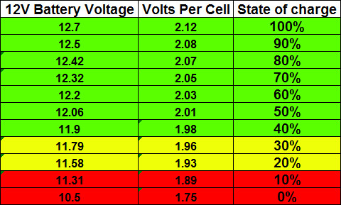
Under point (a) you'll directly measure the volt drop, which could be low: If the battery condition is poor, it would explain the pull down to 10.5V under the coil -ve earth test, with no fault in the wiring.b) voltage between coil - supply and engine block during cranking?
c) voltage between coil - supply and battery - during cranking?
d) battery voltage when cranking?
e) voltage between battery - and engine block while cranking?
f) battery voltage with headlamps on?
g) Spark quality (or does it run) when the coil + is taken direct to battery +?
As it might be useful to check the earthing and battery condition too.
Gassing Station | Wedges | Top of Page | What's New | My Stuff