Sparking problem
Discussion


Totally confused. ran the SEAC up.
Battery voltage when running 12.9 volts
Voltage across coil when running 4.2 volts
Engine off - battery voltage 12.5 volts
Earthed coil negative terminal back to battery negative, With ignition on voltage across coil 9.06 volts....
Not a bloody clue what that means but car runs great and coil stays cool......
KKson said:
Totally confused. ran the SEAC up.
Battery voltage when running 12.9 volts
Voltage across coil when running 4.2 volts
Engine off - battery voltage 12.5 volts
Earthed coil negative terminal back to battery negative, With ignition on voltage across coil 9.06 volts....
Not a bloody clue what that means but car runs great and coil stays cool......
That means Thankyou! i am surprised at that 4.2v when in operation though. The 9.06v is fine just means you might have a few more turns on the coils.Battery voltage when running 12.9 volts
Voltage across coil when running 4.2 volts
Engine off - battery voltage 12.5 volts
Earthed coil negative terminal back to battery negative, With ignition on voltage across coil 9.06 volts....
Not a bloody clue what that means but car runs great and coil stays cool......
You may be not be totally au fait with the installation.
So I just did some of the same measurements on the 400SX. This is a running car (that doesn't, touch wood, catch fire):
For reference, battery voltage 12.48V.
Battery voltage headlamps on = 12.1V
Voltage between coil + and battery -, ignition on, not cranking = 12.39V.
Voltage between coil + and battery -, as above but coil - grounded to battery - = 6.0V.
So your problem might be, why is the voltage so high? It might indicate a fault with the ballast resistor.
I would therefore add to my measurements request above:
h) Disconnect battery - and then battery +.. Ignition on. Measure resistance between battery + clamp and ignition coil primary +.
Reconnect battery + first then battery -.
KKson said:
Totally confused. ran the SEAC up.
Engine off - battery voltage 12.5 volts
Earthed coil negative terminal back to battery negative, With ignition on voltage across coil 9.06 volts....
Ballast resistor, innit?Engine off - battery voltage 12.5 volts
Earthed coil negative terminal back to battery negative, With ignition on voltage across coil 9.06 volts....
Maybe not such a great idea of mine to run direct from battery + to coil + except as a quick test to see if it runs, no more than 20 seconds, to keep coil heat down.
Also Bigfish please carry on with the rest of the tests and report back, the more data we have, the easier it will be to diagnose the fault.
Edited by adam quantrill on Thursday 28th May 18:40
adam quantrill said:
KKson said:
Totally confused. ran the SEAC up.
Engine off - battery voltage 12.5 volts
Earthed coil negative terminal back to battery negative, With ignition on voltage across coil 9.06 volts....
Ballast resistor, innit?Engine off - battery voltage 12.5 volts
Earthed coil negative terminal back to battery negative, With ignition on voltage across coil 9.06 volts....
Maybe not such a great idea of mine to run direct from battery + to coil + except as a quick test to see if it runs, no more than 20 seconds, to keep coil heat down.
Also Bigfish please carry on with the rest of the tests and report back, the more data we have, the easier it will be to diagnose the fault.
Edited by adam quantrill on Thursday 28th May 18:40
Its fine to run the feed like that, ballast resistors are only needed for 9v coil systems so it shouldn't have one.
Well it depends on the coil rating, if yours is a 12V then you'll not be wanting one, but with 10.5V at the primary the spark should still be healthy. Trouble is when cranking the battery volts will drop maybe as low as 8-9V. If the ballast resistor isn't bypassed (during cranking) then you might not have enough volts to get a decent spark.
Hence the need to carry on with the rest of the tests.
Hence the need to carry on with the rest of the tests.
Edited by adam quantrill on Thursday 28th May 19:36
adam quantrill said:
Well it depends on the coil rating, if yours is a 12V then you'll not be wanting one, but with 10.5V at the primary the spark should still be healthy. Trouble is when cranking the battery volts will drop maybe as low as 8-9V. If the ballast resistor isn't bypassed then you might not have enough volts to get a decent spark.
Hence the need to carry on with the rest of the tests.
Im sure he's not put a 9 volt coil on on this system should be 12v, electronic ignition as it is. They were only employed to stop points and condensers. burning out.Hence the need to carry on with the rest of the tests.
Edited by Bristol ave fag on Thursday 28th May 19:41
There is another reason too - to make starting more reliable.
As the battery voltage drops during cranking, when you have a ballast resistor in series you defeat it - short it out. On earlier V8's this was done with an extra tap on the solenoid, I guess in later cars from the starting relay.
Then even though the battery volts are lower, the coil is getting full whack (or more, if it's a 6V primary) and you get a nice fat spark just when you need it most.
Bedtime for me, will visit later
If nothing else, many may benefit from this topic by checking what their Wedges coil circuit is made up of
Looks like there are 12 Volt 9 Volt and 6 volt systems of which some will very likely be modifications carried out by present or previous owners
Big problems do sometimes arise when parts are replaced with incorrect ballast resistors or ignition coils
Posted the following the other day in an attempt to save some possible confusion
Page 1 Sunday
You comment single white wire from ignition which has a good 12.5v
Do you mean there is 12.5 volts at the white ignition supply cable that is connected to the coil + positive and that voltage drops to 10.5 volts when earthing the coil negative
If so
The ignition supply to the coil is dropping by 2 volts when under coil load......this is a fault
Apart from poor or burnt connections, the only other problem could be the fitting of the wrong voltage ignition coil
Some ignition circuits use a 9 or even 6 volt coil and a ballast resistor in series with the coil supply (White cable) to drop the voltage
Fitting a lower voltage coil in a 12 volt circuit could cause a volt drop to increase
If nothing else, many may benefit from this topic by checking what their Wedges coil circuit is made up of
Looks like there are 12 Volt 9 Volt and 6 volt systems of which some will very likely be modifications carried out by present or previous owners
Big problems do sometimes arise when parts are replaced with incorrect ballast resistors or ignition coils
Posted the following the other day in an attempt to save some possible confusion
Page 1 Sunday
Penelope Stopit said:
Bigfish_74 said:
Tried to diagnose the voltage drop by disconnecting all from the coil other than the 12v ignition supply. So a direct earth to battery from coil negative and the single white wire from ignition which has a good 12.5v are the only connections but still get the voltage drop across + - to 10.5v. Also checked with the old coil and the same result, are we sure the coil isn't meant to drop the voltage under load?
Don't leave the coil powered up for too long, it will overheatYou comment single white wire from ignition which has a good 12.5v
Do you mean there is 12.5 volts at the white ignition supply cable that is connected to the coil + positive and that voltage drops to 10.5 volts when earthing the coil negative
If so
The ignition supply to the coil is dropping by 2 volts when under coil load......this is a fault
Apart from poor or burnt connections, the only other problem could be the fitting of the wrong voltage ignition coil
Some ignition circuits use a 9 or even 6 volt coil and a ballast resistor in series with the coil supply (White cable) to drop the voltage
Fitting a lower voltage coil in a 12 volt circuit could cause a volt drop to increase
Penelope Stopit said:
Bristol ave fag said:
KKson said:
No problem.
Out of curiosity I will head down to my garage after I've completed my due "working from home" and measure the voltages at the coil on both my SEAC and 390SE to see what they are with ignition on. Cheers.
Nice, ok if you start the car and let it idle and measure the voltage you should see 12v at the coil . now engine off with the ignition on and coil trigger side earthed you should see a drop across the 2 coil terminals to 10.5v. I think this is where the confusion lays in two different conditions.Out of curiosity I will head down to my garage after I've completed my due "working from home" and measure the voltages at the coil on both my SEAC and 390SE to see what they are with ignition on. Cheers.
You keep avoiding all information that I have posted
The supply at the ignition coil needs to be as close as possible to battery voltage when the negative side of the coil is earthed
The only time that the voltage is found to be 3 or 6 volts lower than battery voltage is when measuring a ballast resistor circuits supply voltage at the coil
Have you even bothered to think what a ballast resistor circuit achieves ?
You are getting it all wrong
Why persist in posting about transformers ?
It doesn't make any difference whatsoever that an ignition coil is a transformer
The test that I suggested is a static test, no engine running and is a very simple test
The test proves if there is a good or poor supply to the ignition coil positive and it is the only possible way of proving it 100%
This information is common knowledge
Each time a coil supply voltage is lowered by increments of 1 volt the secondary voltage is lowered due to less current flow through the primary coil which then doesn't create a strong enough magnetic field
I suggest you do some studying
What do you think ?
We all make mistakes
Thought perhaps........
Penelope Stopit said:
Bristol ave fag
What do you think ?
We all make mistakes
Thought perhaps........
Your theory has already been proven wrong by KKson he has 9.06v doing the same test coil not earthed 12v coil earthed 9.06v so the mistake is yours.Or is his car about to burst into flames too?What do you think ?
We all make mistakes
Thought perhaps........
Move on.
Edited by Bristol ave fag on Thursday 28th May 22:51
Bristol ave fag said:
Penelope Stopit said:
Bristol ave fag
What do you think ?
We all make mistakes
Thought perhaps........
Your theory has already been proven wrong by KKson he has 9.06v doing the same test coil not earthed 12v coil earthed 9.06v so the mistake is yours.Or is his car about to burst into flames too?What do you think ?
We all make mistakes
Thought perhaps........
Move on.
Edited by Bristol ave fag on Thursday 28th May 22:51
You don't understand the workings of a simple 12 volt ignition circuit
A 12.5 Volt ignition coil supply shouldn't drop to 10.5 Volts when the negative side of the coil is connected to battery negative (obviously all ignition components need to be of the correct voltage)
You comment that a 12.5 Volt ignition coil supply should drop to 10.5 Volts when the negative side of the coil is connected to battery negative
You have posted a load of nonesense here
Don't advise me to move on when it is you posting the nonesense
Commenting move on doesn't put things right
There is much information posted to the internet (reputable articles not forum nonesense which is always readily available) that proves you have posted nonesense here
Bigfish_74 will hopefully ignore the nonesense you have posted
If your nonesense is taken as fact by anyone and they were to carry on using an ignition circuit with a 2 volts volt drop, there is every chance of part of the circuit overheating and causing bigger problems, a fire being the worst case
Below is a link to one of many articles that can be found posted to the internet that proves Bristol ave fag has posted nonesense
https://www.motor.com/magazine-summary/mastering-b...
Will include a couple of paragraphs from it
Along with the variety of parts in the primary circuit and possible causes of a no-start or a misfire problem comes a bigger challenge for troubleshooting. You can make the job easier and faster, however, if you remember a few fundamentals:
1) You need enough primary voltage to generate the required secondary voltage in the coil. A loss of just 1 volt on the primary side can cost you several thousand volts on the secondary side.
2) Voltage and current are affected by resistance in the primary circuit. An open circuit or a short circuit or abnormally high or low resistance will knock primary voltage and current out of spec.
3) Many experienced technicians say that checking coil resistance doesn't tell you the complete story. They like to check the coil and the primary circuit under a load, with current flowing. Following this principle leads to some basic voltage-drop tests of the primary circuit that apply fundamentally to good old breaker points and modern distributorless systems.
4) Primary voltage at the coil positive terminal should be close to system voltage under all conditions for these other systems. There aren't too many different ignition designs, but even if you don't have them memorized, a good tuneup manual will give you the specs fast.
I rest my case - Bristol ave fag has posted much nonesense to this topic
Don't tell me to move on
Anybody can replicate the test and get similar results..... KKson for one has already done this for us and his coil drops to 9.06v. It has been proven in practical tests. You just cannot accept the results. As for a 9 or 6 v coil. they have never been used on these vehicles or any other vehicles with electronic ignition.
Where do you think KKson's voltage is going?
This is what is said about the primary circuit in the Magazine you posted..... "Voltage and current are affected by resistance in the primary circuit"
Please read the results of the test correctly and move on to the next step that is how diagnostics is carried out.!
Edited by Bristol ave fag on Friday 29th May 09:32
Edited by Bristol ave fag on Friday 29th May 09:44
one issue here is that using a test bulb to provide the load can result in mis-information, not from a voltmeter but from the brightness of the bulb .. even a bulb fed with 9-10volts will still seem very bright. That's not a good test if you are relying on your eyes to gauge whether a bulb is bright or not, and using that to gauge the integrity of the supply circuit.
Trust the voltmeter .. if it says you have 9 to 10volts when the coil is earthed then you have a supply issue, you should see battery voltage come what may. It's a feed from the battery after all. It goes through a switch, fuse, relay etc and all are potential areas for high resistance, but it starts at the battery and it starts therefore at battery voltage.
What happens if you do the test with the coil earthed, leave the voltmeter connected, then momentarily put a good quality fused live feed direct from the battery positive .. if the voltmeter jumps from the 9 or so volts up to battery voltage then that proves you have a supply issue.
Now go back to the original circuit and trace back through the circuit with your voltmeter until you find the point at which the voltage jumps from 9 volts up to 12 volts. Then fix the fault. There may be more than one fault of course, and the 2-3 volt drop may be accumulative.
When I earthed the negative on the coil to battery negative there was a good old spark, which I didn't particularly like. My SEAC runs lovely so I'm not going to play with it too much, in case I accidentally fry something. It's taken me 8 months to get it up and running so I'm a little precious about it. I will however repeat the tests on the 390SE later to see what voltage I have across that coil also.
KKson said:
When I earthed the negative on the coil to battery negative there was a good old spark, which I didn't particularly like. My SEAC runs lovely so I'm not going to play with it too much, in case I accidentally fry something. It's taken me 8 months to get it up and running so I'm a little precious about it. I will however repeat the tests on the 390SE later to see what voltage I have across that coil also.
That's very good of you and don't worry about what is being seen on your SEAC it is as it should be.Ignition in "on" position. Battery voltage 12.53v. Direct earth from coil negative to battery negative - voltage across coil 9.16v, so very similar to SEAC. The 390SE had a full rolling road health check the other year and the engine is in very fine fettle.
I'll leave that data with you sparky boys and "girl" then......... Sorry if I've confused things?
I'll leave that data with you sparky boys and "girl" then......... Sorry if I've confused things?
KKson said:
Ignition in "on" position. Battery voltage 12.53v. Direct earth from coil negative to battery negative - voltage across coil 9.16v, so very similar to SEAC. The 390SE had a full rolling road health check the other year and the engine is in very fine fettle.
I'll leave that data with you sparky boys and "girl" then......... Sorry if I've confused things?
Very good of you to check your coil voltagesI'll leave that data with you sparky boys and "girl" then......... Sorry if I've confused things?
Looks like your vehicle has a 9 Volt coil plus a ballast resistor that drops the ignition voltage from approx 12 volts to approx 9 volts
The above can only be proven by connecting coil back as standard, connecting voltmeter to coil positive and cranking the engine over while reading the voltmeter, would also need to measure battery cranking voltage, both the voltages are needed to prove anything
Bigfish_74 if you're still with us
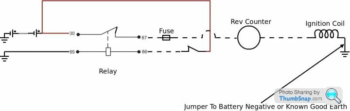
The following diagram may well show how your ignition coil circuit is wired
I haven't drawn a loop of cable at the rev counter but there very likely will be a loop at the rear
Suggest that you first measure for battery voltage at the relay and if all is good work forward to the rev counter and then the coil
Gassing Station | Wedges | Top of Page | What's New | My Stuff