G40R 2.5 litre Duratec
Discussion


At this point, the starter motor gear failed to engage with the flywheel, only screeching and grinding instead of turning the engine. The car was beached on my uneven drive, but I managed to drag it by winch into my garage.
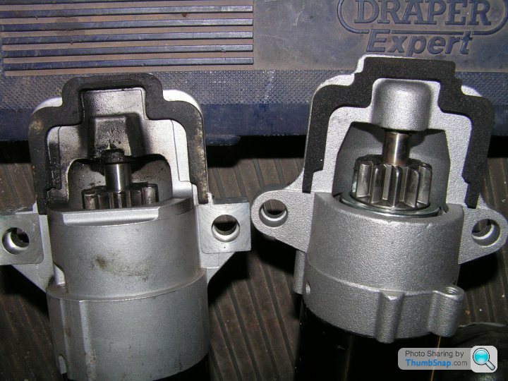
The starter gear failure was caused by the flywheel on the new 2.5 engine having a different offset than the original 2 litre engine. The 2 litre engine appeared to be using a Mazda flywheel vs the Ford pattern flywheel on the new 2.5. Therefore the starter gear was only engaging by a couple of mm, until it finally stripped. A new Powerlite starter with Ford offset was purchased at beneficial discount, thanks to referral from Peter at Raceline. Cheers guys!!
What a job to fit the thing though, due to use of cap head bolts to secure the original starter. With the engine in the car, it was hardly possible to apply a wrench. A lifetime collection of obscure tools finally allowed me to persuade the bolts loose. The new unit was fitted using hexagon head flange bolts, much better.
Mazda starter on left, Powerlite Ford on right:
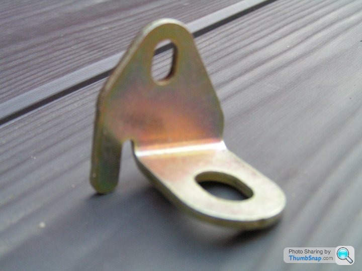
I also discovered this handy bracket, from a Ford Mondeo. It stabilises the front of the starter motor, reducing stress on the main lugs.
This takes us to summer 2019, at which point my work stress was sapping so much energy that I was unable to make any further progress until spring 2020. I then started looking more effectively at the need for an oil cooler and extra wiring for the camshaft actuator and sensor, as follows…….
The starter gear failure was caused by the flywheel on the new 2.5 engine having a different offset than the original 2 litre engine. The 2 litre engine appeared to be using a Mazda flywheel vs the Ford pattern flywheel on the new 2.5. Therefore the starter gear was only engaging by a couple of mm, until it finally stripped. A new Powerlite starter with Ford offset was purchased at beneficial discount, thanks to referral from Peter at Raceline. Cheers guys!!
What a job to fit the thing though, due to use of cap head bolts to secure the original starter. With the engine in the car, it was hardly possible to apply a wrench. A lifetime collection of obscure tools finally allowed me to persuade the bolts loose. The new unit was fitted using hexagon head flange bolts, much better.
Mazda starter on left, Powerlite Ford on right:
I also discovered this handy bracket, from a Ford Mondeo. It stabilises the front of the starter motor, reducing stress on the main lugs.
This takes us to summer 2019, at which point my work stress was sapping so much energy that I was unable to make any further progress until spring 2020. I then started looking more effectively at the need for an oil cooler and extra wiring for the camshaft actuator and sensor, as follows…….
Here is the original remote filter and pipe work, removed from its location on the lower chassis rail near the right front corner of the sump. Due to restricted space, it’s a small filter and the pipes are only -8, which is typical motorbike size, not great for a 2.5 litre car engine. Made to a budget and good enough for the original application I suppose. Time for rethink.

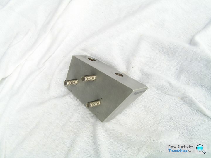
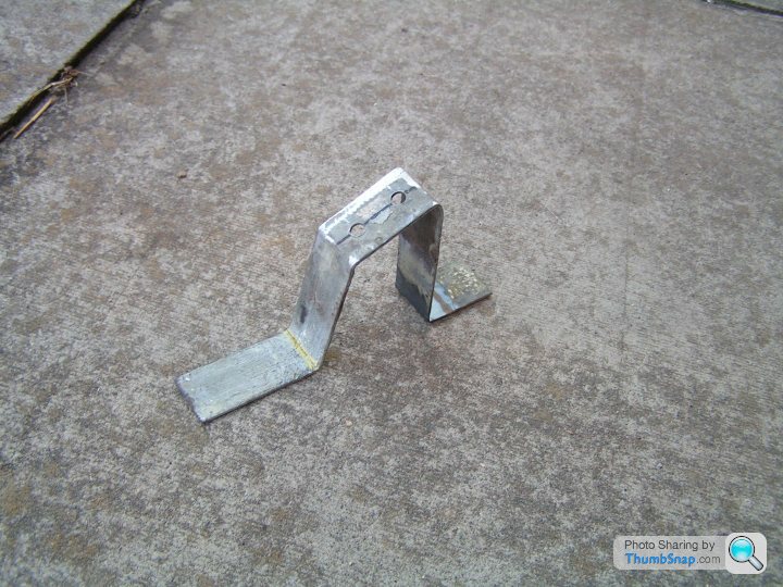
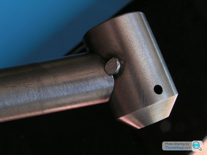
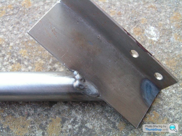
I decided to relocate the filter to up on the timing cover, at the front of the engine. This gives easy access, accommodates a larger filter and makes a cleaner route for the pipes. Here is the bracket I made to attach the Mocal filter head to the timing cover. It’s a weird shape to get the filter level while the engine is inclined at 10°. The bracket is made from heavy aluminium angle with a stiffening gusset brazed on the end and stainless M8 studs.
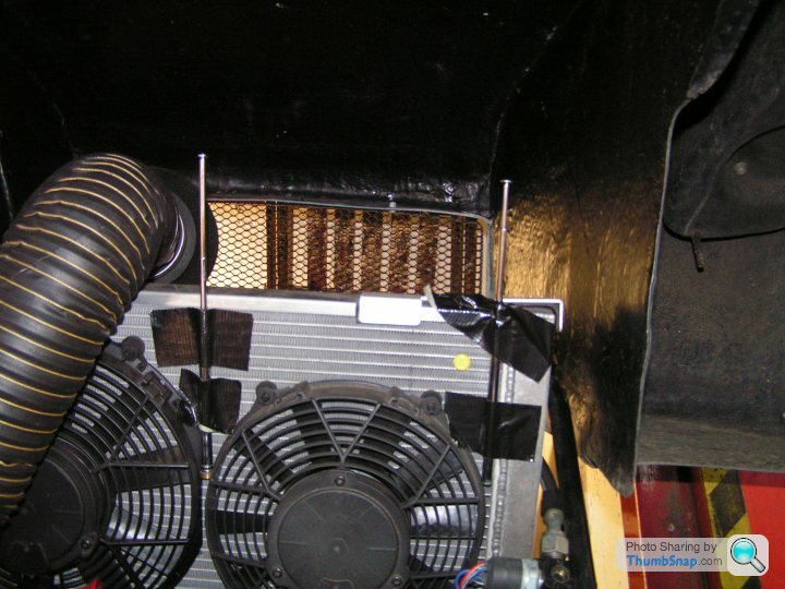
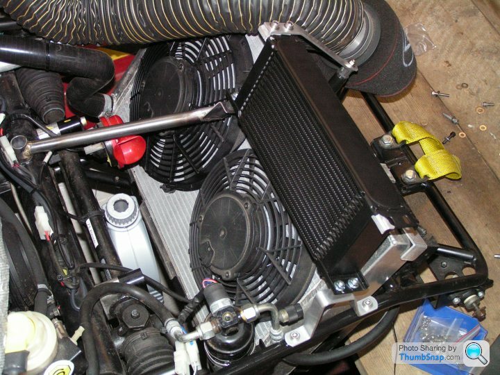
How much room is there under the bonnet for an oil cooler? I did consider mounting it very low down in the nose of the car, immediately behind the grill. I decided against this due to the long pipe run required and because it might rob cooling air from the radiator. Instead, it could go behind/above the top of the radiator to the right of the air filter. In the picture, closing the bonnet onto old telescopic aerials allows the clearance available for the cooler to be measured.
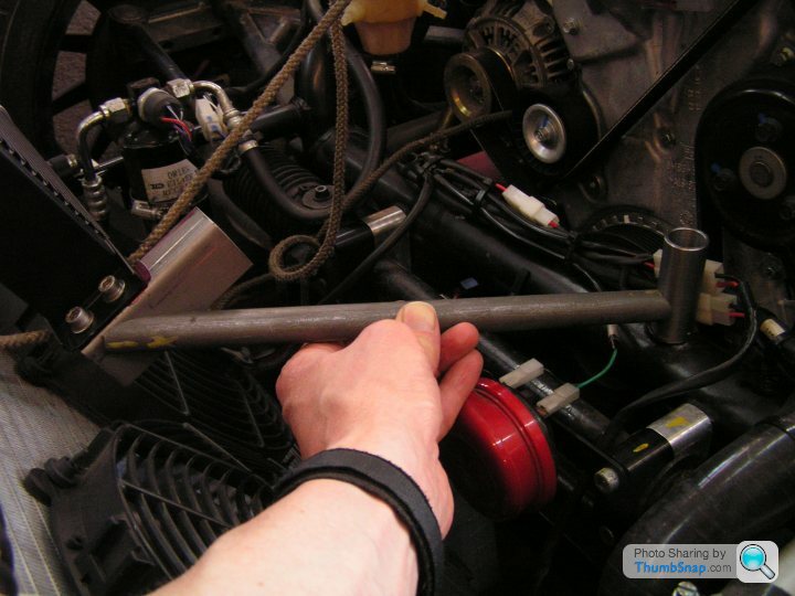
On to the pipe work. I reckoned there would just be room for -10 pipe coming off the oil manifold plate at lower left of the block. See picture of the oil manifold earlier in the thread. It was tight and I had to reduce the height of one of the -10 to ½” BSP adapters. Slightly blurry picture comparing standard to modified Earls adapter.
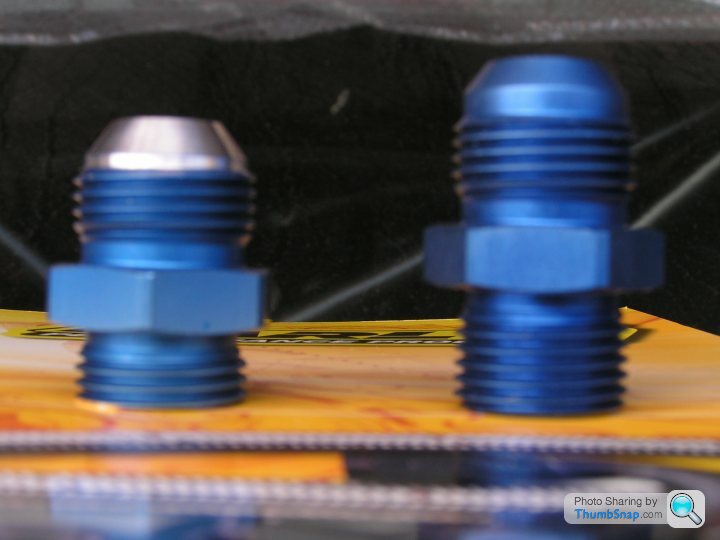
I’m lucky living only 20 minutes from Silverstone. It turned out that my discount at Earls Performance from way back when I was bike racing is still registered on their system. What nice people to deal with – highly recommended. No stress there!
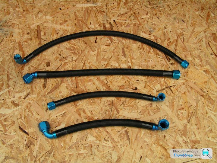
Here are all the pipes after some back and forth to Earls crimping the ends. The ends are Earls Auto-Mate with steel crimp sleeves painted epoxy black by me. The hose is Pro-Lite 390
It is -10 size coming off the engine oil manifold, crossing over to -12 at the cooler. I was really pleased with how these pipes turned out.
I’m lucky living only 20 minutes from Silverstone. It turned out that my discount at Earls Performance from way back when I was bike racing is still registered on their system. What nice people to deal with – highly recommended. No stress there!
Here are all the pipes after some back and forth to Earls crimping the ends. The ends are Earls Auto-Mate with steel crimp sleeves painted epoxy black by me. The hose is Pro-Lite 390
It is -10 size coming off the engine oil manifold, crossing over to -12 at the cooler. I was really pleased with how these pipes turned out.
Pipes sorted, so now on to the wiring. First the engine loom, which needs wires adding as follows: upgrade from 2 wire to 3 wire cam position sensor, cam actuator wires, oil temperature gauge wire, wiring for new STACK oil pressure gauge.
To remove the engine loom you first need to take away the air box and windscreen washer bottle to disconnect the 47 pin bulkhead connector. Remove the throttle bodies from the inlet manifold. Remove the alternator. Then you are free to take off and dissect all this spaghetti.
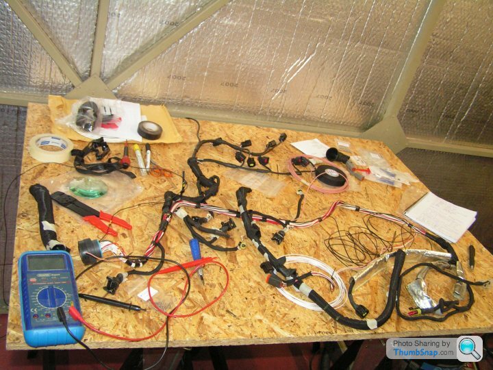
After a lot of careful splicing and continuity checking we end up with a modified loom like this.Some extra pins are needed in the 47 way bulkhead connector. There are enough spare holes available for this. These are Deutsch DTM pins (and sockets) available from PoleVolt, for example. It’s also very handy to have the insertion/extraction tool. I think I got that from RS. The bulkhead connectors are from the Deutsch HDP20 series. It’s all on the web if you search around.
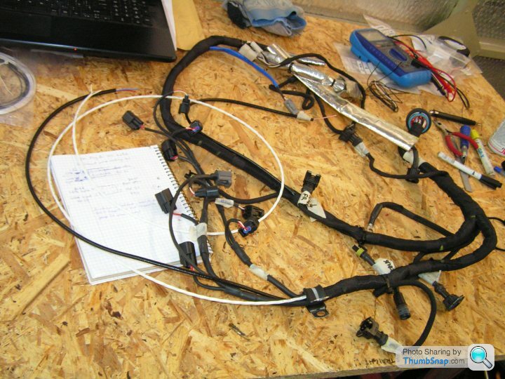
At the top of the picture, the blue sleeved tail with DTM connector on the end is for the STACK gauge sensor and oil warning switch. Near it, there is a black sleeved tail with a single pink wire at the end for the oil temperature sender, located in the sump. That’s waiting for a spade connector.
At the left of the picture is a long white wire coiled up. That is a 3 core screened cable for the cam position sensor. This will be trimmed to length and connector added later after re-fitting to the engine. Near that is a long black tail with red and blue wires at the end for the cam actuator.
Take lots of pictures and label everything when you are ripping this loom apart. Tracing the original wires is arduous, as they are all white, black or red.
I refitted the engine loom and amazingly the engine still ran without frying any of the electronics.
With relief I moved finally to the dashboard and ECU wiring.
To remove the engine loom you first need to take away the air box and windscreen washer bottle to disconnect the 47 pin bulkhead connector. Remove the throttle bodies from the inlet manifold. Remove the alternator. Then you are free to take off and dissect all this spaghetti.
After a lot of careful splicing and continuity checking we end up with a modified loom like this.Some extra pins are needed in the 47 way bulkhead connector. There are enough spare holes available for this. These are Deutsch DTM pins (and sockets) available from PoleVolt, for example. It’s also very handy to have the insertion/extraction tool. I think I got that from RS. The bulkhead connectors are from the Deutsch HDP20 series. It’s all on the web if you search around.
At the top of the picture, the blue sleeved tail with DTM connector on the end is for the STACK gauge sensor and oil warning switch. Near it, there is a black sleeved tail with a single pink wire at the end for the oil temperature sender, located in the sump. That’s waiting for a spade connector.
At the left of the picture is a long white wire coiled up. That is a 3 core screened cable for the cam position sensor. This will be trimmed to length and connector added later after re-fitting to the engine. Near that is a long black tail with red and blue wires at the end for the cam actuator.
Take lots of pictures and label everything when you are ripping this loom apart. Tracing the original wires is arduous, as they are all white, black or red.
I refitted the engine loom and amazingly the engine still ran without frying any of the electronics.
With relief I moved finally to the dashboard and ECU wiring.
There needs to be a single extra terminal inserted in the ECU plug at A26 for the cam actuator signal, plus a few new terminals in the bulkhead to match what was done to the engine loom for oil pressure & temperature gauges. ECU terminals came from SCS Delta. SCS also had to do a small soldering job on the Tornado ECU board to reconfigure it from the 2 wire to 3 wire cam sensor.
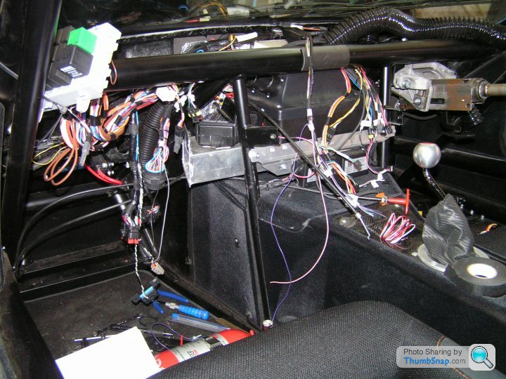
With the dashboard panel removed, the heater fan is blocking access to the bulkhead connector.

Having removed the ECU and heater fan, there is access to all the wiring. The lower of the two bulkhead connectors is for the engine.
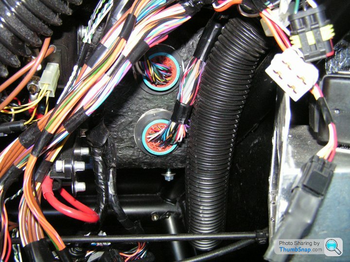
The blue wire for the cam actuator signal continues from bulkhead to ECU pin A26. Then a few more wires from bulkhead to instruments. The original fuel gauge was a bad joke, so this has been swapped for a Racetech oil temperature gauge. The connection at the back of the Racetech gauge is exactly the same as the original fuel gauge, so all that needs to be done is to splice in the wire from the oil temp sender instead of the fuel tank sender. The STACK oil pressure gauge has its own plug to be added to the loom.
With the dashboard panel removed, the heater fan is blocking access to the bulkhead connector.
Having removed the ECU and heater fan, there is access to all the wiring. The lower of the two bulkhead connectors is for the engine.
The blue wire for the cam actuator signal continues from bulkhead to ECU pin A26. Then a few more wires from bulkhead to instruments. The original fuel gauge was a bad joke, so this has been swapped for a Racetech oil temperature gauge. The connection at the back of the Racetech gauge is exactly the same as the original fuel gauge, so all that needs to be done is to splice in the wire from the oil temp sender instead of the fuel tank sender. The STACK oil pressure gauge has its own plug to be added to the loom.
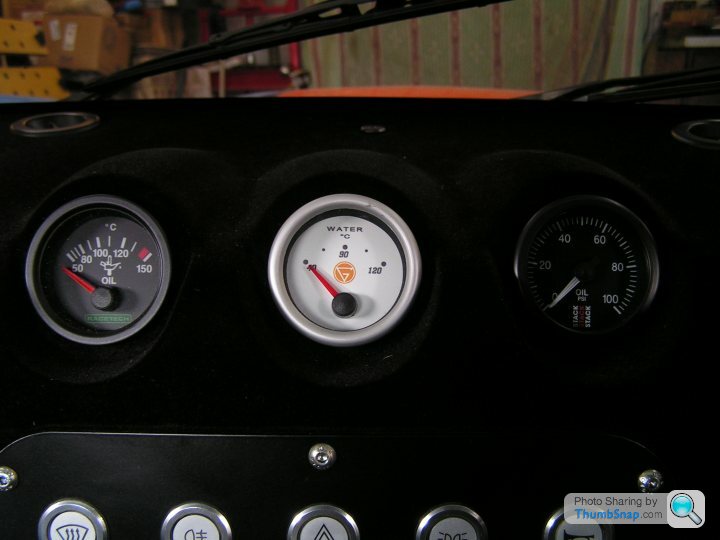
The original water temperature gauge is fed by a PWM output from the ECU, so I have kept that for the time being. I don’t like the white dial face though, or the lack of scale divisions. I’ll try to swap that out later.
Reason for the STACK oil pressure gauge is that the original Ginetta oil gauge was always reading low. When the brand new engine was also reading supposedly low pressure, I realised that it must be the gauge at fault, not the engines.
Reason for the STACK oil pressure gauge is that the original Ginetta oil gauge was always reading low. When the brand new engine was also reading supposedly low pressure, I realised that it must be the gauge at fault, not the engines.
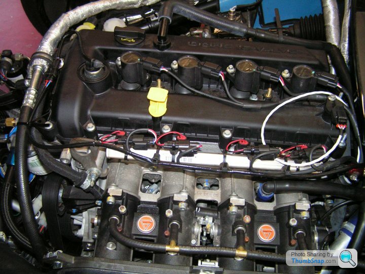
Engine loom connected up with cam sensor & actuator plugged in. The correct plug for the cam actuator does not seem to be readily available, so I used some “Superseal” female connector terminals to slide on to the pins inside, then potted and heat shrink sleeved to secure. The resulting tail leads to a Superseal connector located at the front of the cam cover.
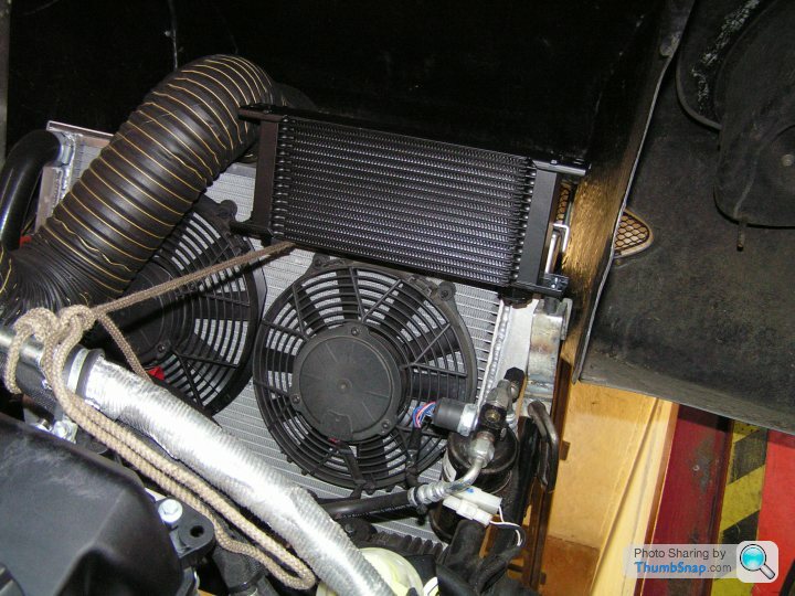
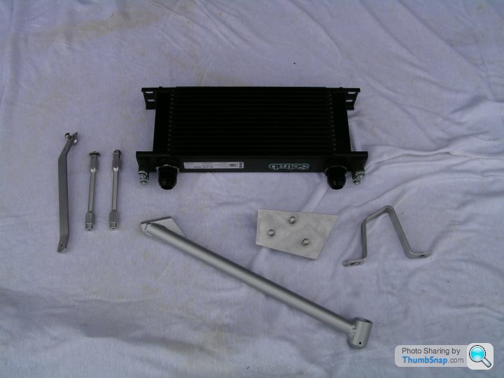
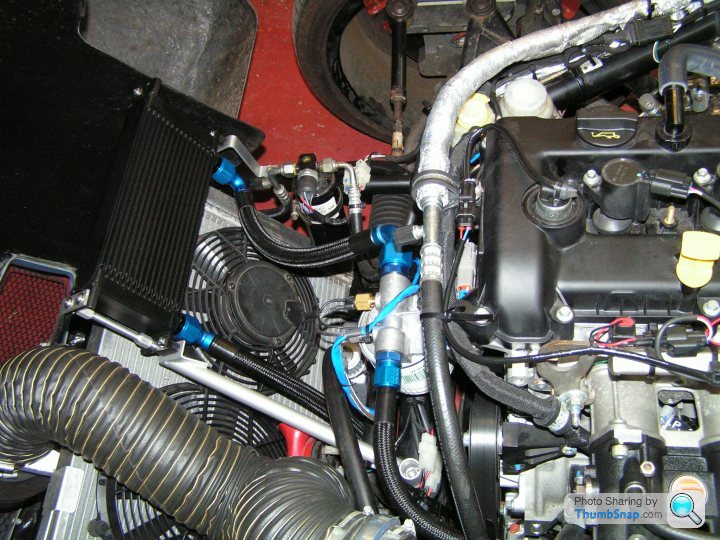
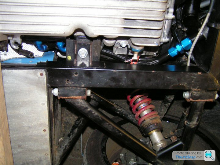
Overall view of cooler installed. Fits with just about perfect finger gap clearance to the closed bonnet. Not pictured, I have used some soft foam draught-excluder tape stuck to the bonnet to close the gap.
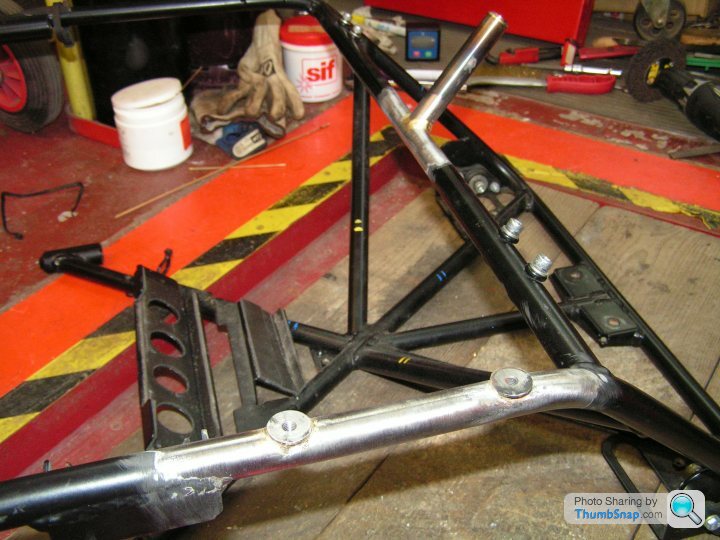
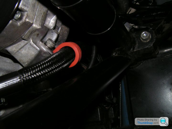
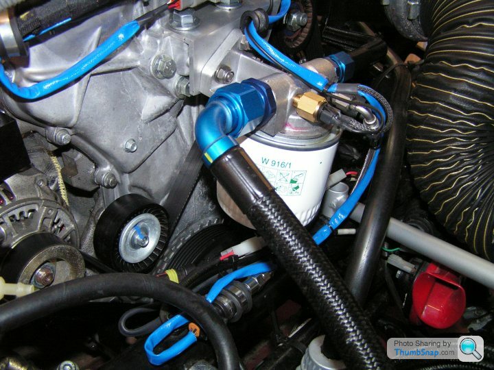
Remote filter mounted on bracket to timing cover. The blue loom goes along the -3 pipe to remote mounted STACK pressure sender. This filter mounting gives the shortest pipe run to the cooler and allows room for the larger filter which can easily be changed.
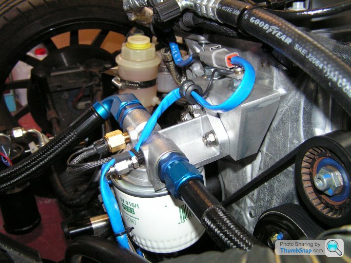
The filter is a Mann W916/1, which is a typical ¾” UNF Ford fitting for e.g. Capri 2.8i. It’s a good quality filter with pressure relief valve and anti-drain back valve. The oil pressure comes up instantly upon engine start, despite the long and large diameter pipes. Oil temperature remains below 100°C even on the rolling road.
Remote filter mounted on bracket to timing cover. The blue loom goes along the -3 pipe to remote mounted STACK pressure sender. This filter mounting gives the shortest pipe run to the cooler and allows room for the larger filter which can easily be changed.
The filter is a Mann W916/1, which is a typical ¾” UNF Ford fitting for e.g. Capri 2.8i. It’s a good quality filter with pressure relief valve and anti-drain back valve. The oil pressure comes up instantly upon engine start, despite the long and large diameter pipes. Oil temperature remains below 100°C even on the rolling road.
Off again to SCS Delta in Norfolk for proper rolling road calibration. The cam control wiring worked fine. Power was OK at about 210 BHP, but can see the lumpy torque curve and the torque dying off from 6500rpm, flow limited. That’s because of the under-sized throttles (45mm) carried over from the original 2 litre engine and the restrictive exhaust.
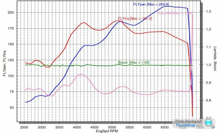
The uneven torque is probably down to the highly compromised exhaust, which is still the factory original. The inlet manifold is for the original 2 litre and there is a 5mm step up to the larger 2.5 inlet ports. There isn’t enough meat to easily open up the manifold. The throttles are 45’s where it needs 48’s or 50’s. All this needs to be fixed and the engine should be good for 250bhp +. The main thing is the healthy torque from 4000rpm up. The engine does not rely on high rpm, so it copes better with the wide-gapped original gearing and allows relaxed cruising in 5th. Debatable numbers aside, it drives a LOT quicker than the old 2 litre, which was supposed to be 175bhp, but probably wasn’t.
The uneven torque is probably down to the highly compromised exhaust, which is still the factory original. The inlet manifold is for the original 2 litre and there is a 5mm step up to the larger 2.5 inlet ports. There isn’t enough meat to easily open up the manifold. The throttles are 45’s where it needs 48’s or 50’s. All this needs to be fixed and the engine should be good for 250bhp +. The main thing is the healthy torque from 4000rpm up. The engine does not rely on high rpm, so it copes better with the wide-gapped original gearing and allows relaxed cruising in 5th. Debatable numbers aside, it drives a LOT quicker than the old 2 litre, which was supposed to be 175bhp, but probably wasn’t.
Opening the bonnet after the power runs, the air box lid was found to have separated from the mounting flange. We glued, taped and tie-wrapped it back on to the flange. Then another full power run showed much reduced mid-range torque and mid-range power down by about 25bhp, although only a small loss in top end power. I knew the air box was quite a poor design, but didn’t imagine it was THAT bad!
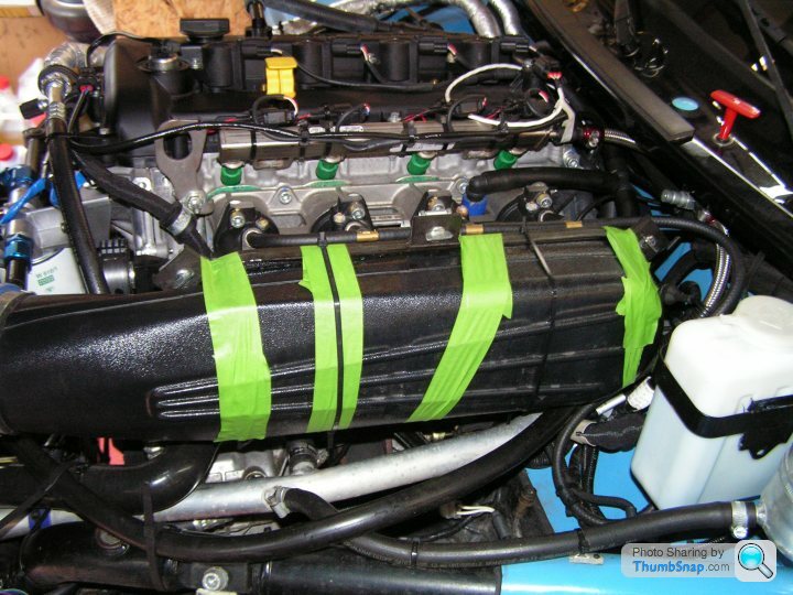
The calibration was left the same and at home I have now replaced the air box by the largest foam filter that Pipercross produce. It slots straight on to the existing back plate. The windscreen washer bottle will eventually have to find a new home.
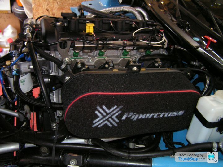
The calibration was left the same and at home I have now replaced the air box by the largest foam filter that Pipercross produce. It slots straight on to the existing back plate. The windscreen washer bottle will eventually have to find a new home.
Gassing Station | Ginetta | Top of Page | What's New | My Stuff