Graphics interface for the 14CUX
Discussion


spitfire4v8 said:
Blitz .. When I was with John Ravenscroft (ex TVR factory engine guru) he was with me in a chimaera with his (presumably lucas developer) software running .. and there's a fuel trim learned when the car is stationary, at idle, with full working temperature and stable idle and throttle inputs at idle. The ecu then learns a trim which is applied over the whole rev range. live lambda trimming is then applied on top of that trim. It's the long term adapted trim learned at idle that's cleared by disconnecting the ecu. This is what he described to me 15+ years ago so i hope I remembered it correctly. Does it tie in with what you're seeing on the diagnostics ?
I'd love to buy whatever is required to get this up and running for me (Im rubbish at electronics level stuff!) .. I've always shied away from mapping the Lucas because you never know what the live trim and adapted trim is being applied by the lambdas so you don' know how far the base map is out .. if these can now be read it makes mapping the Lucas a real possibility.
I got exactly the results you describe when testing the units lambda response after a reset- and the really good news after a bit more testing is both the Long term and Short term trim are available from the 14CUX- I managed to get both readings on some test software from Colin Bourossa last night. As you say the long term trim says so much about the overall mapping state of the car,or if sensor inputs are wrong, where the ECU is still coping. The jump from this to re mapping is quite a big one, as all we have at the moment is the basic map load point data tables based on airflow and RPM, and even if you know a specific load point that runs rich or lean at a specific RPM so you change it, that same load point may also be used at a different RPM / airflow, so I dont know the effect it will have. I need to download a test copy of WinOLS and see if I can work outs whats going on, now I have more data. I'd love to buy whatever is required to get this up and running for me (Im rubbish at electronics level stuff!) .. I've always shied away from mapping the Lucas because you never know what the live trim and adapted trim is being applied by the lambdas so you don' know how far the base map is out .. if these can now be read it makes mapping the Lucas a real possibility.
Edited by blitzracing on Wednesday 20th June 12:16
Edited by blitzracing on Wednesday 20th June 16:48
Are- as said this is a fuel / ECU only diagnostic, and it only has one feed from the ignition but I would think you should get an RPM reading from the rev counter as you crank the engine if the ignition primary is firing. The diagnostic wont pick up no fuel pressure, but you can at least switch the pump on and off and listen to it.
Ribol said:
blitzracing said:
Are- as said this is a fuel / ECU only diagnostic, and it only has one feed from the ignition but I would think you should get an RPM reading from the rev counter as you crank the engine if the ignition primary is firing. The diagnostic wont pick up no fuel pressure, but you can at least switch the pump on and off and listen to it.
Sounds like this is getting better by the day, what is your sum up of what you can do with this software now? Is there more to come?"Read" inputs:
Water temp.
Fuel Temp.
Speedo signal.
RPM.
Target idle speed (as set in Eprom)
Supply voltage
Stepper position.
Throttle pot voltage
AFM voltage.
Current fuel map number and live load positions in the map, Fuel map adjustment (engine size scaling).
Fuel pump status.
Gear status (for auto boxes)
Fault codes
Lambda trim offsets (see below)
Copy Eprom contents.
Sensor logging facility.(text based)
"Write" inputs:
Position the stepper motor
Turn the fuel pump on and off
Clear fault codes
Current developments:
Lambda trim displays.
At the moment you can have either the ECU short fuel trim or long fuel trim, but it requires a different library file to be used for either display, and the graphic display does not support both trims at the same time. The trim values show how much the ECU has to trim the amount of fuel from base map setting to get the lambda probes to switch correctly. It has 255 steps available in total so it starts at position 128 (mid point) and adds trim to remove fuel (shown as 0 to + 100% )or subtracts trim to make the mixture richer (shown as 0 to -100%), so this goes the opposite way you would expect. This value is what the ECU is applying to get the mixture right, NOT what the lambda outputs are. So if a Lambdas voltage output is reading rich at say 1 volt the ECU, the ECU adds a positive trim value, and if the Lambda voltage is 0 volts reading lean, the ECU removes fuel trim.
The long term trim value does not change much once set, and far as I can see at the moment, will only alter if a lambda stops switching (rich or lean) for a period at idle. Ive not managed to get mine to move from a very good +3% even by boosting the fuel pressure, as the short term trim simply compensates within its range, so the Lambdas keep switching. I think I need to put the wrong fuel chip to introduce a big fueling error in, to see when the long term fuel trim changes. The short term trim simply changes the mixture on a second by second basis, and can be seen by a constantly fluctuating reading if all's well.
There will be an update to put both long and short trim levels one one display, and some additional fault code information as not all the codes are listed, but not forgetting this software is FREEWARE, and this extreme thanks to Colin and Dan Bourassa, for being so generous with both their skill and time at cracking this so far and not charging us a Cent, I suspect we will owe them many beers!
Edited by blitzracing on Saturday 30th June 18:59
You have nothing to worry about there basically, and Id expect you will get a speed reading once the car is moving- I think it would have thrown a fault code otherwise. The throttle pot needs tweaking to get a 5% reading with the throttle shut, as less than this could be mistaken by 0 volts by the ECU and it can throw a TP error. The fuel trim values you have are fine- but its the long term fuel trim, the basic mixture setting the ECU sets with a warm engine and at idle, and the two sides of the V8 can be different without any issues. The latest version of RoverGauge now has extra error codes and switchable long / short term fuel trim and the short term is useful for looking at the live fueling status of the engine at different RPM bands, that you cant see with the long term trim. It also has some tweaks to the AFM scaling.
Download here
http://code.google.com/p/rovergauge/downloads/deta...
Download here
http://code.google.com/p/rovergauge/downloads/deta...
bubblehead said:
Mark my screen has a line for target idle speed but it's empty.....it's a 4.3 precat if that matters but it seems to idle fine at about 1000rpm, just curious why i don't have a target idle speed?
I can only think the software equests data from locations in the ECU memory, so if the location is different on different versions of the ECU microcode you might not find what you are looking for. Griffith 500 said:
I have had problems with rich running at start up, spitting fuel on the garage wall. When I looked at the Rovergauge I found that the long term compensation was at -100% on both lamdas. No fault codes and all sensors looked OK. I changed the CO voltage on the AFM from 1,8 V to 1,0 V, and now the long term compensation changed to +14 % on one lambda and -26 % on the other. Does this make any sense?
You may have just solved one of the great riddles of the 14CUX.... . I have never mangaged to read a shift in the actual lambda cycling when messing around with the CO trim setting, so Ive always concluded this trim makes no difference at all on the cat map- plus I was also told by a 14CUX guru (Not M.A.) that the CO trim circuit was turned off in cat mode, so Ive never doubted this fact. Now with RoverGauge being able to read the long term trim, we can actually see what the ECU is doing to the mixture- NOT whats the lambda probes are reporting post combustion. Its probably why M.A. gives a trim voltage for his chips, but when I asked him why he simply said it was a factory setting
  - and at the time I had no idea that the ECU even had a long term trim facility- (M.A. kept that fact close to his chest) let alone one you could set with CO trim.
This has a lot of potential- as where we have been blindly setting the DC voltage on the CO trim- we could in fact have been mis-setting the long term trim, so the ECU is banging against the limits on the short term trim that can lead to poor low low speed performance (read shunting). We need to try setting up a car that shunts and see if it improves things.
Edited by blitzracing on Saturday 28th July 20:48
A bit of help needed here from anyone who has a cable, as I cant get the expected results from my car on the long term fuel trim values. My long term values display correctly just once, and then next time it updates they default to 0, or 255, and then stays that way even without the engine running. Ive not noticed this on any of the TVR's however, so can anyone please just double check two things for me?
1) Please someone just do the same test as TV8 did and see if the long term trim changes with the CO trim on the side of the AFM. The engine must be warm and at idle when you do this and it may take a while to change (no more than 2 mins). Idealy you want to set the long term trim to be as near the mid point (0) as possible, and average out the two banks of the V8.
2) Double check which way the long term trim value changes in relation to the AFM setting- I expect the the trim value to become more +ve as you wind the AFM screw clockwise to richen the mixture. I need to check the Long term trim is the same as the short term trim, that adding fuel trim makes the mixture leaner. Another easy test to do would be to remove the vacuum line from the fuel regulator so it boosts the fuel pressure at idle, this should cause the long term trim to move in a positive direction. You may need to block the hole off in the plenum wheer the pipe was as the extra air will alter the mixture as well.
thanks
Mark
cmb said:
Note that the current version of the software (0.3.4) is displaying the short-term lambda fuel trim inverted. Both the long-term and short-term fuel trim values actually should show a higher number with more fuel delivery. We verified that this is the case by using an oscilloscope to monitor the injector pulse width. I hope to soon release a new version with the correct polarity displayed.
I also experimented by writing different values to the long-term trim memory location. (This location was initially at 0 counts with a warm engine at tickover.) Writing the minimum value (-256 counts) caused the engine to stumble and almost die, but the short-term trim values increased substantially to compensate, and the normal idle speed was restored. Conversely, setting the long-term trim to its maximum value (+255 counts) caused a slight increase in engine speed, but this was again corrected by the short-term trim, which decreased substantially.
--Colin
Hi Colin- Please when you do this dont simply swap the display polarity- but add something like add fuel / subtract fuel, otherwise it will cause great confusion over the different revisions of RoverGauge and documentation thats already out there.I also experimented by writing different values to the long-term trim memory location. (This location was initially at 0 counts with a warm engine at tickover.) Writing the minimum value (-256 counts) caused the engine to stumble and almost die, but the short-term trim values increased substantially to compensate, and the normal idle speed was restored. Conversely, setting the long-term trim to its maximum value (+255 counts) caused a slight increase in engine speed, but this was again corrected by the short-term trim, which decreased substantially.
--Colin
Thanks
Mark
You can convert the log file data into Excel by first editing the file to replace "," with a "tab" using notepad or the like, then cut and paste the result into Excel, so each logged value is in a different cell. You can then use the Graph function if you want some nice graphics. Makes it a whole lot easier than trying to read raw data.
Heres what Colin told me about the adjustment factor:
The 16-bit adjustment value shown above the map is multiplied by the 8-bit value read from the map itself. There is a different adjustment value for each map, and it seems to be the most significant change between maps for different engine displacements. Of course, after this multiplication, there are a number of other adjustments made (based on coolant temperature, fuel temperature, main voltage, and, for cat maps, lambda feedback.)
Ive got a selection of maps I can plug in and see if there is a common values relation to specific engine sizes.
You could try having a play with WinOLS now we can read the Eprom contents easily instaed of messing around at a bits and bytes level, and its designed for Bosch fuel maps that the Lucas uses. It costs far to much for the full version but you can download a demo copy here:
http://www.evc.de/en/download/down_winols.asp
Cant say I know how to drive it however.........
http://www.evc.de/en/download/down_winols.asp
Cant say I know how to drive it however.........
You need the datasheet for the Motorola 6803U4 microprocessor for the assembly code. As for the emulator- is it not simply a case of getting an Eprom emulator for the 27xxx series with a USB interface and programming the relevant address locations directly with a PC? The Guy who could really help on this is Fanc Buxton:
http://www.stunnedbuffalo.demon.co.uk/sbr.html
I drop him a mail as this is out of my league.
http://www.stunnedbuffalo.demon.co.uk/sbr.html
I drop him a mail as this is out of my league.
Edited by blitzracing on Saturday 13th October 09:53
Thats correct- but please try an ECU reset, and make sure the long term trim drops to zero before resetting bit by bit on a hot engine, it seems odd that you would be running 100% long term, yet the short term is fine. The long term trim could be a red herring that needs investigating.
I think the strange issue with the long term trim dropping to zero's down to engine temp- Ive seen this before, and the engine needs to be in the low 90's to get a sensible reading- My G33 runs at around 85'c and the long term never gets set at all. Not that I care as I don,t run the catalyst map other than to experiment with...
The throttle pot is self adjusting to an extent and is adaptable within a range of 80 to 500 mV closed throttle. Within this range, the ECU will adapt to the initial setting and use it as a reference.
If the TPS should fail, the ECM will use a default value of 576 mV and the MIL will be illuminated. A diagnostic trouble code (17) is set when sensor output is less than 78 mV for longer than 160 milliseconds Throttle Position
So id suspect at some point the TP has gone open circuit at some point with the ignition on, but as there are no time stamps on the error code you wont know when this happened- if its cleared now, and the readings are smooth, Id not worry about it.
Ive put some extra manuals on the CD on fault code generation.
The MAF readings are highly variable - The values Ive used are the figures Mark Adams uses as test examples simply shown in percentage terms, but engines with a different cam, idle speeds and general engine condition will cause the values to be outside the range, the AFM is very sensitive at low air flows, so small airflow changes give big voltage changes- but as it says in the notes it needs to be a long way out from the ball park figures to show and AFM failure
Im not sure whats going on with the short term lambda readings when they freeze- but dont forget this is a correction value the ECU is applying- not the lambda voltages themselves- so you would need to observe what Rovergauge is doing along side the physical voltages to see whats really going on. If it is the ECU overloading (seems unlikely at idle- are the other values still updating?) , try reducing the scan rate RoverGauge asks for the data to reduce the load on the ECU- its called poll interval under options and its set for .5 of a second (500 millisecnds by default) so you could try 1000 milliseconds.
I check the grounding plug wiring, but the cars seem to run OK without them (so far at least??).
Edited by blitzracing on Sunday 4th November 10:15
The ECU only has a range of mixture adjustment available to correct a fueling error, so in the case of long term trim Id expect the ECU to pick up that it has make adjustments in one direction more than the other on the short term to get the switching of the probes even (Its mark space ratio of the waveform). The probes should have an equal time spent "lean" and "rich" at a perfect fueling point, but if its more one way than the other, the long term level can be moved to allow the short term to then cycle evenly again. So you could get a case that the long term has hit its limit, but the short term can still shift the mixture enough to make the probe switch, it just wont be even. In the real world the switching signal is pretty ragged at its best, its very difficult to visually see the switching ratio. I have managed however to replicate various conditions and waveforms are here, 1/3 down the page:
http://www.g33.co.uk/fuel_injection.htm
The ECU can make a very large fueling correction (I think its around 20%) so if its hitting the stops on either trim, something is significantly wrong to cause it to do this.
As for the TP errors:
17 is a code for a failed test during power on (wrong setting or open circuit) and 19 is low throttle pot output with high AFM output- this is a contradiction in terms, so either the AFM output has glitched high or the throttle pot has gone open circuit when the airflow his high.
As to the question of faults- yes RoverGauge will only show faults as the ECU reports them. In the case of Lambda switching the ECU is not very sensitive to a fault conditions, it really takes the probe to stop switching for a period to throw a code- not simply if the fuelling is a bit "out".
Edited by blitzracing on Wednesday 7th November 18:37
Pulling the AFM off will cause the ECU to go into limp home mode fuel map, so will give you a completed false result as to the cause. In limp home the AFM output will be ignored completely and it fuels on Throttle pot and RPM only- You need to check the map number your are running with the AFM in place, check for fault codes, and look at the Lambda values to see what the fueling doing.
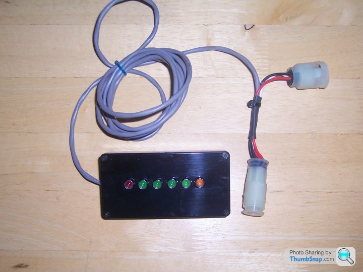
I knocked out 5 units based on an audio level meter with 5 LED's reading the upper and lower voltages levels the lambda's displayed. Problem was by the time Id got hold of the correct OEM plugs and sockets for the lambda's, wired them up with screened cable, made up the circuits, put it in a nice box and then calibrated it it was not really economic to do time wise, even at £50 a unit. You are better off buying a simple analogue test meter off ebay, (you need one with a lower DC volage range of 2.5 volts) and simply extending the test leads so you can read it in the cabin.
http://www.ebay.co.uk/itm/multimeter-draper-analog...
Heres one of the LED units:
http://www.ebay.co.uk/itm/multimeter-draper-analog...
Heres one of the LED units:
Gassing Station | General TVR Stuff & Gossip | Top of Page | What's New | My Stuff