Tamiya 1:12 McLaren MP4/6 Rebuild/Upgrade
Discussion


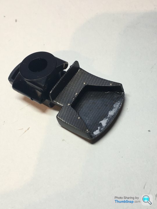
Frustrating work on the rear brake ducts. As per a previous post, I opted to scrap the p/e inners and make my own 4-piece items. This worked well, but I noticed a cracked decal in the inside of one. I tried to flat it back and told myself that putting another decal on top would be ok. I kidded myself into finishing them both before accepting that the repaired one does indeed look crap:
So I’ve dis-assembled the inner plates (only secured with pva luckily), and I’ll have to think how to fill it. I really don’t want to strip the whole thing and start again. Again.
At least the other side looks fine:
Still trying to find a decent satin clear coat. Tamiya is too glossy to my eyes. Might try flat base again but it’s a hassle, and inconsistent too.
robemcdonald said:
I recently made my own satin clear by mixing future and the artist flat coat you recommend ages ago.
It took a bit of fine tuning (adding more flat) but worked pretty well.
I was quite surprised how easy it was.
Outstanding work as always by the way.
Thanks - the Winsor & Newton varnish? I've got Matt and Satin, so I might try mixing them 50/50 and see what happens.It took a bit of fine tuning (adding more flat) but worked pretty well.
I was quite surprised how easy it was.
Outstanding work as always by the way.
robemcdonald said:
I cant recall the brand, but I guess any should work. Worth a try for no risk or cost?
Just tried it - very odd; just can't get the balance right to get a bit of sheen, but not too matt. Tried 50/50, 60/40 & 75/25.Someone on F1M forum mentioned Mr. Hobby Satin. Might try that.
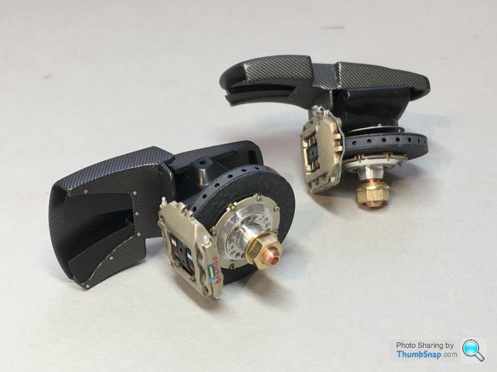
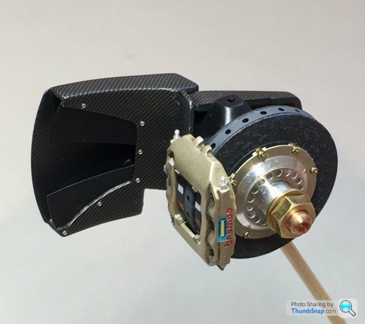
Lost momentum on this one recently. Lots of stuff needed re-doing, and re-doing again because it didn’t look right or whatever. Anyway, I’ve now completed the rear brakes, ducts and uprights.
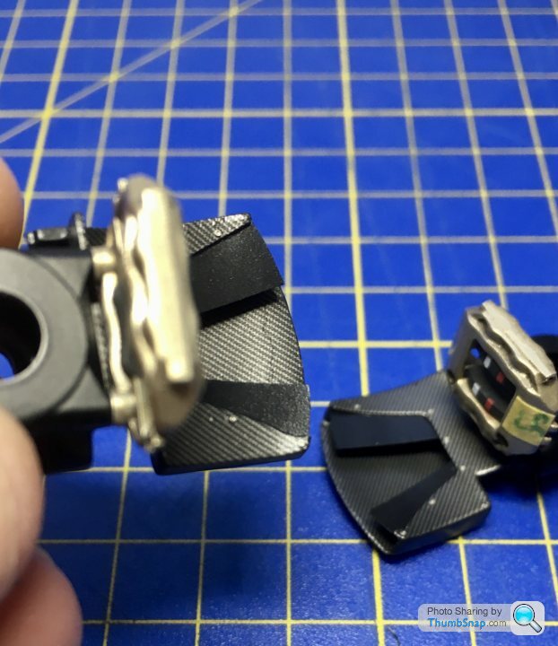
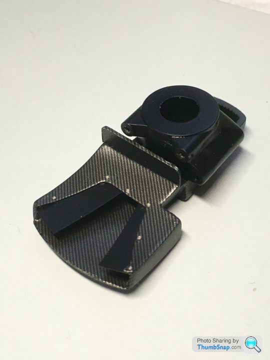
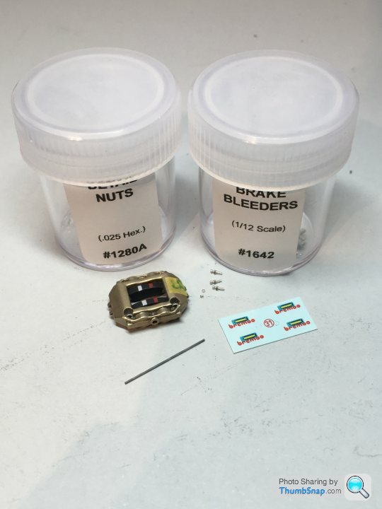
First, the callipers has their Transfer pipes & nuts, pad retainers, screws, pipe unions and decals added:
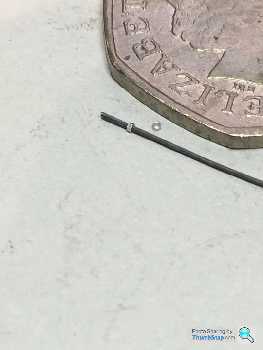
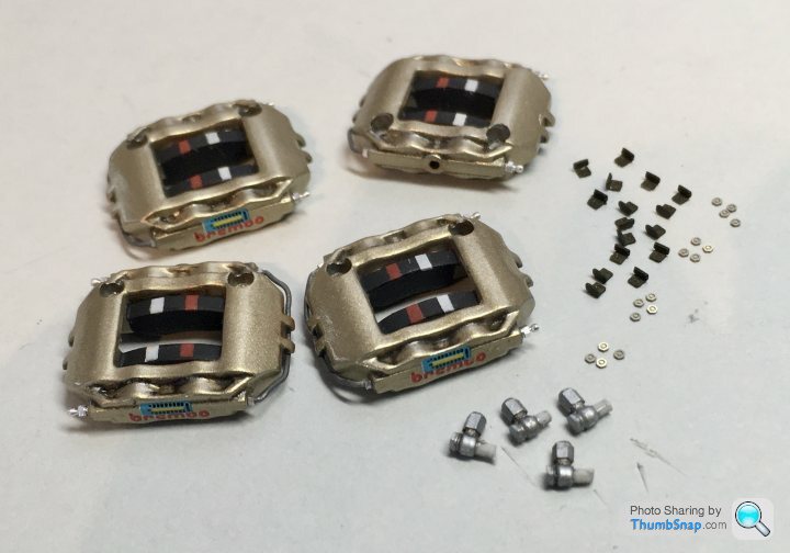
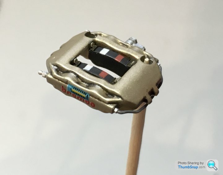
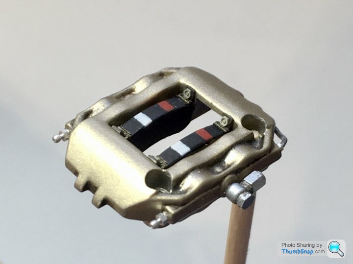
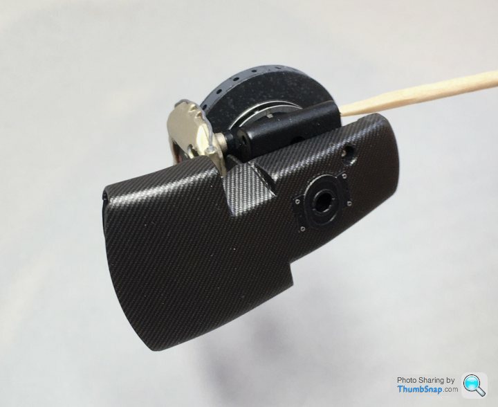
Then on to the ducts, which I modded by adding separate inner plates from 0.2 PlaPaper. Fasteners were Top Studio rivet heads. Final assembly was straightforward; I used the original kit screws for the callipers and ducts, but stuck a p/e bolt head over the cross heads:
 |https://thumbsnap.com/qNfo7qyn[/url]
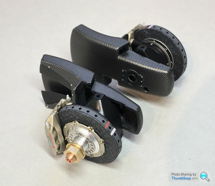
Now back to the inlet tray and trumpets...
First, the callipers has their Transfer pipes & nuts, pad retainers, screws, pipe unions and decals added:
Then on to the ducts, which I modded by adding separate inner plates from 0.2 PlaPaper. Fasteners were Top Studio rivet heads. Final assembly was straightforward; I used the original kit screws for the callipers and ducts, but stuck a p/e bolt head over the cross heads:
|https://thumbsnap.com/qNfo7qyn[/url]Now back to the inlet tray and trumpets...
I made a notional airbox seal out of lead wire painted Tamiya Rubber Black:
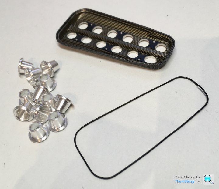
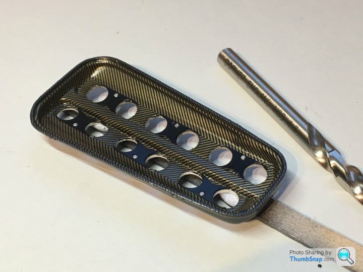
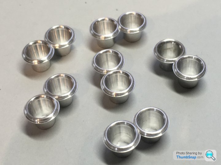
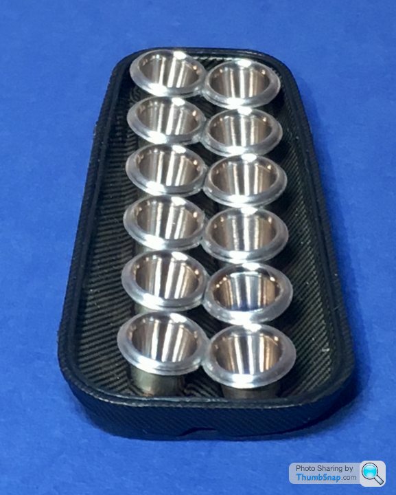
And tried PVA’ing the trumpets in pairs along their flats to aid alignment:
Then pressed them into their sockets using a slip gauge to keep them level:
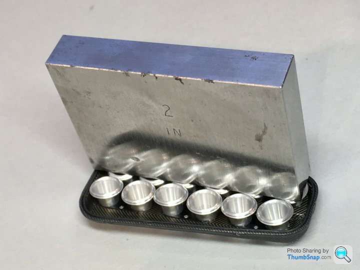
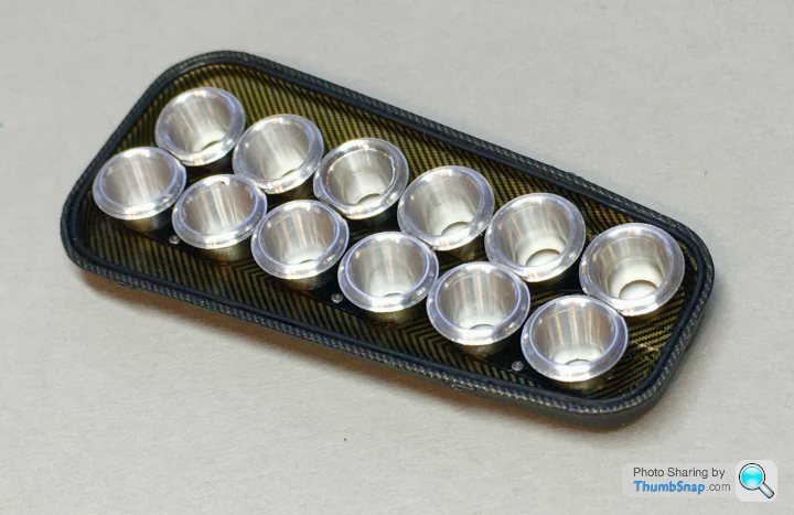
Didn’t really work because some were loose in their sockets. Anyway, with some minor adjustments they will be fine. Not glued in place yet, but pretty much there:
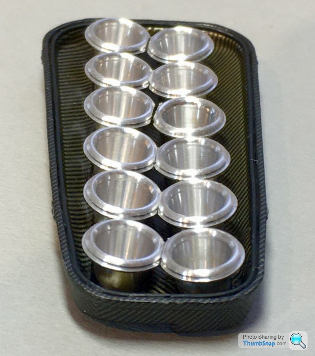
The box of completed sub-assemblies is slowly but surely filling up:
And tried PVA’ing the trumpets in pairs along their flats to aid alignment:
Then pressed them into their sockets using a slip gauge to keep them level:
Didn’t really work because some were loose in their sockets. Anyway, with some minor adjustments they will be fine. Not glued in place yet, but pretty much there:
The box of completed sub-assemblies is slowly but surely filling up:
dr_gn said:
Frustrating work on the rear brake ducts. As per a previous post, I opted to scrap the p/e inners and make my own 4-piece items. This worked well, but I noticed a cracked decal in the inside of one. I tried to flat it back and told myself that putting another decal on top would be ok. I kidded myself into finishing them both before accepting that the repaired one does indeed look crap:
So I’ve dis-assembled the inner plates (only secured with pva luckily), and I’ll have to think how to fill it. I really don’t want to strip the whole thing and start again. Again.
At least the other side looks fine:
Still trying to find a decent satin clear coat. Tamiya is too glossy to my eyes. Might try flat base again but it’s a hassle, and inconsistent too.
Forgot to mention - the flawed decal was filled with Mr Surfacer 1000 and flatted smooth, and another piece of decal applied. I ended up doing this to both ducts:So I’ve dis-assembled the inner plates (only secured with pva luckily), and I’ll have to think how to fill it. I really don’t want to strip the whole thing and start again. Again.
At least the other side looks fine:
Still trying to find a decent satin clear coat. Tamiya is too glossy to my eyes. Might try flat base again but it’s a hassle, and inconsistent too.
I had my doubts because short cuts rarely work with models, but seemed to get away with it this time.
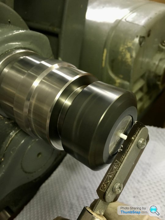
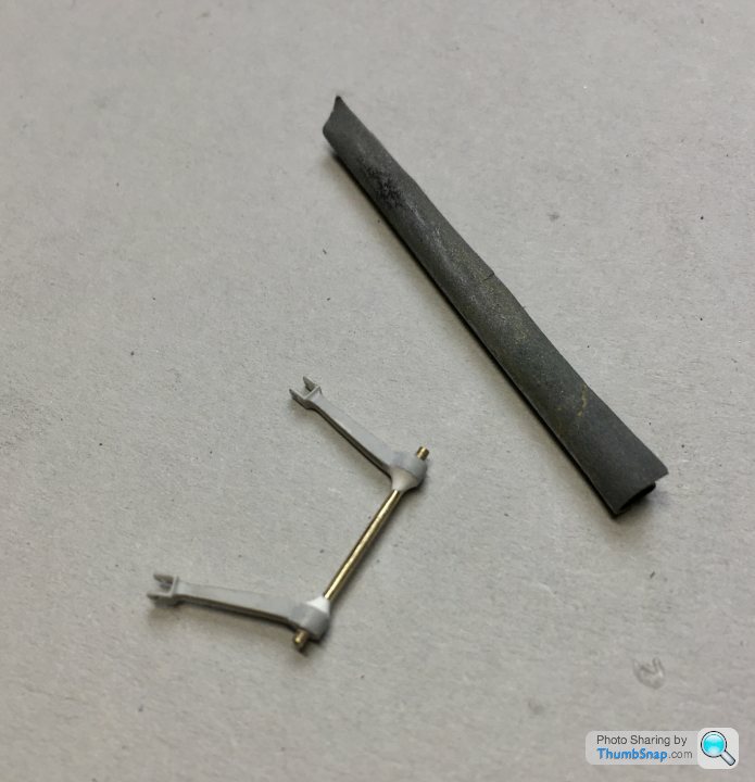
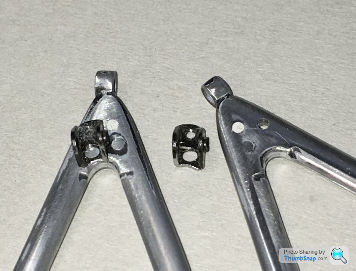
So with the outer bits of the rear suspension done, I turned my attention back to the inner bits, specifically the rockers. The originals are approximately the right size and shape, but need some refinement. For a start, the pushrod mounting fork is too wide, and I wanted to avoid the unsightly loose rattle-fit of the upper rose joint. I made some cheek plates from plastic rod, drilled out on the lathe:
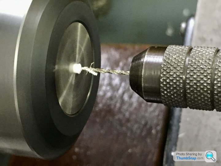
Parted off using a razor saw:
These will be cemented in place before painting.
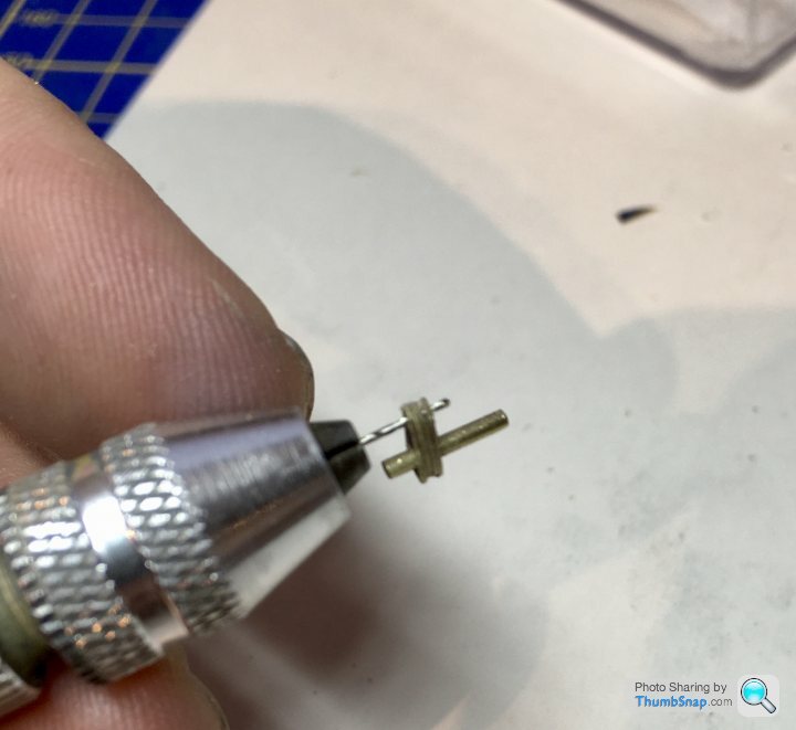
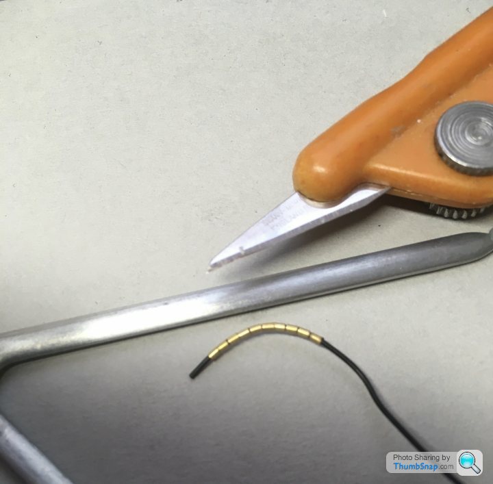
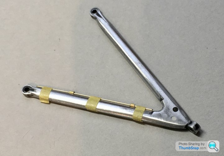
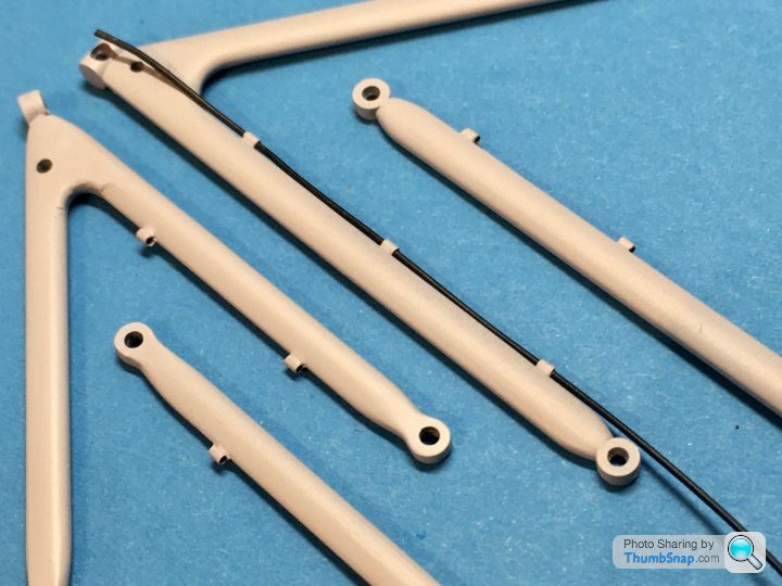
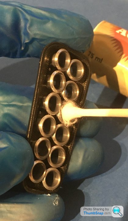
Conversely, the upper damper mounts already have oversized bosses moulded-in, whereas they should really form part of the damper cap mount. The bosses were easily removed, and the aperture sanded to a wider diameter. Replacement spacer pieces were cut from drilled-out brass tube, sanded to length between two abrasive pads:
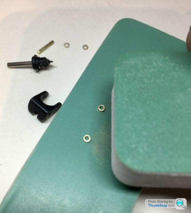
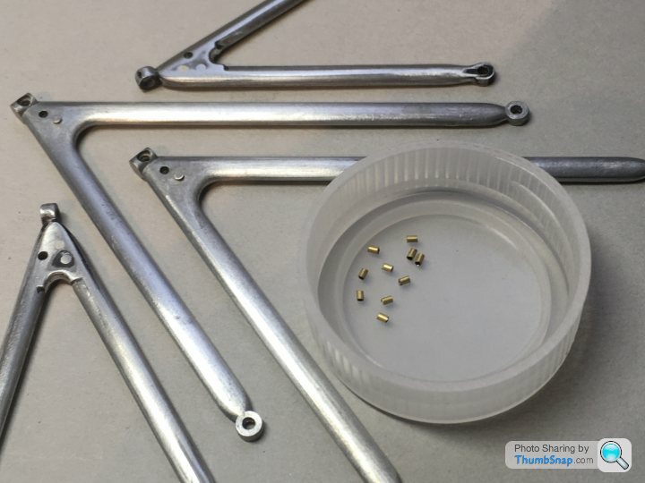
The real car had distinctive gold spacing washers at the ends of these tubes, which I made from brass photo-etch. The other major simplification on the rockers is the anti-roll bar link mount; an unsightly plastic ball joint. Even theTop Studio kit suggests a piece of rod as a replacement. This needed some work, so I represented the real method by scratching some mount plates from brass photo-etch plate (from a Westland Lysander kit I think!):
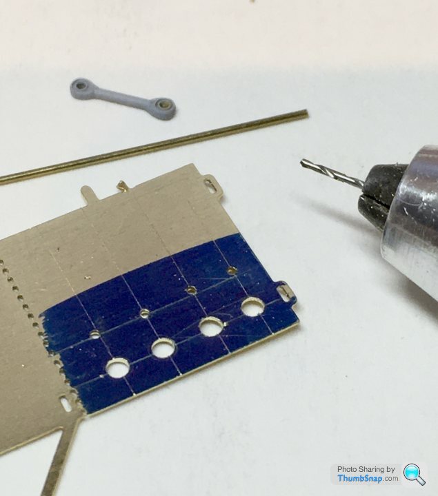
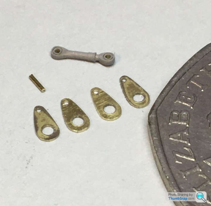
These are the parts, along with a load of other bits of rod etc:
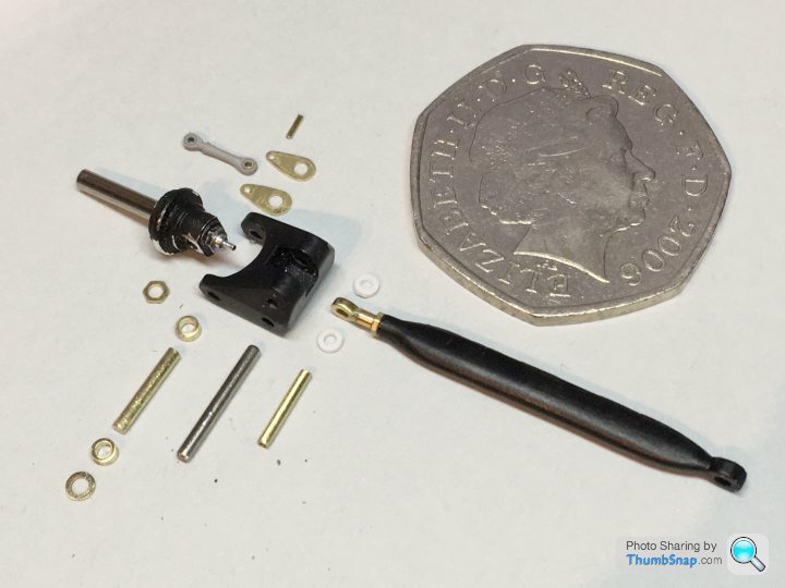
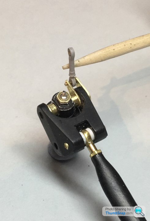
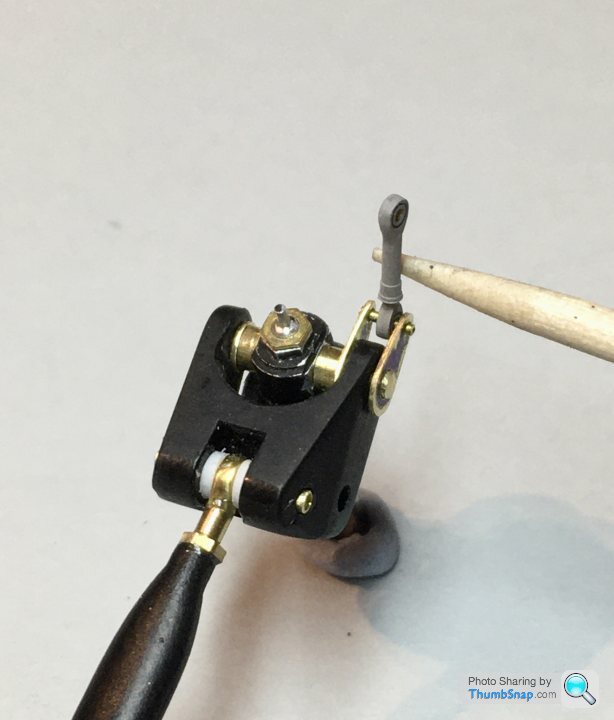
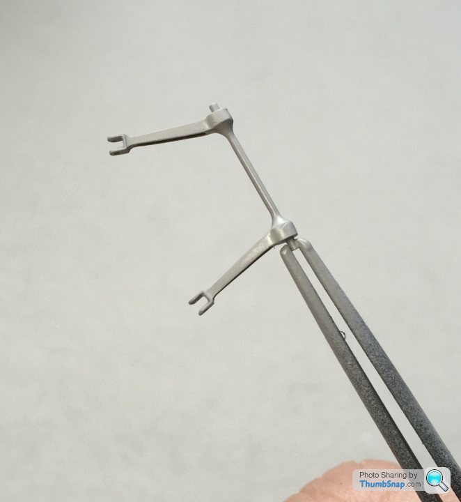
And test-assembled; the laminated Top Studio rose joints really look the part after a bit more finessing with a polishing stick - the laminations are invisible now:
Comparison with original:
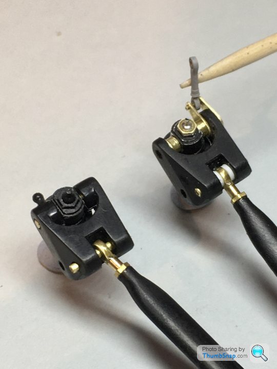
It’s never going to be 100% accurate without major surgery, but when painted up, the contrasting black and brass parts should look fine. The a.r.b. mount plates might need fettling a bit to suit their upper links, but you have to start somewhere...
Parted off using a razor saw:
These will be cemented in place before painting.
Conversely, the upper damper mounts already have oversized bosses moulded-in, whereas they should really form part of the damper cap mount. The bosses were easily removed, and the aperture sanded to a wider diameter. Replacement spacer pieces were cut from drilled-out brass tube, sanded to length between two abrasive pads:
The real car had distinctive gold spacing washers at the ends of these tubes, which I made from brass photo-etch. The other major simplification on the rockers is the anti-roll bar link mount; an unsightly plastic ball joint. Even theTop Studio kit suggests a piece of rod as a replacement. This needed some work, so I represented the real method by scratching some mount plates from brass photo-etch plate (from a Westland Lysander kit I think!):
These are the parts, along with a load of other bits of rod etc:
And test-assembled; the laminated Top Studio rose joints really look the part after a bit more finessing with a polishing stick - the laminations are invisible now:
Comparison with original:
It’s never going to be 100% accurate without major surgery, but when painted up, the contrasting black and brass parts should look fine. The a.r.b. mount plates might need fettling a bit to suit their upper links, but you have to start somewhere...
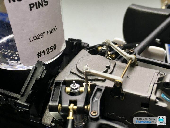
Before going much further with the rear suspension, I thought a dry-run assembly would be a good idea. Having had previous experience building this kit, I was aware of a few potential issues, so temporarily screwed the sump to the old undertray:
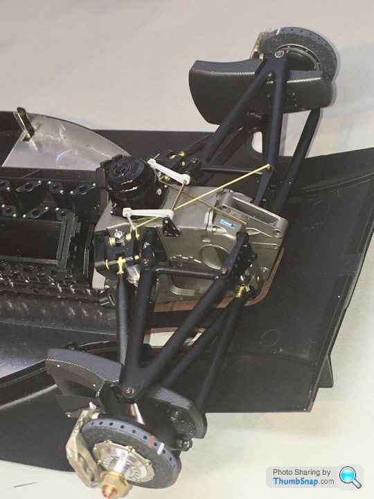
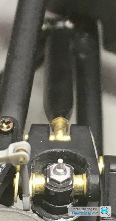
Since I’ve had to make the A.R.B. Mounts, and the Top Studio roll bar is a bit of a d.i.y. affair, I jury rigged the pieces together. It’s nearly there, but there is an issue with the pushrods. As per the kit geometry, the rods are grossly out of line with the rocker pivots - they should be normal to the axes, but as you can see, they aren’t:
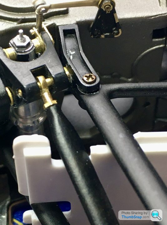
The only realistic choice is to correct the wishbone end - or should I say re-position the pushrod mount to a more favourable position:
Clearly this is moving an error from one place to another, but at least it’s not half as obvious down there. The coke bottle infil pieces may need a bit of fettling to suit, but no big deal there. This results in a far more realistic geometry:
I temporarily omitted the cheek plates I made for the upper pushrod rose joints, but once corrected it should all slot together quite nicely.
Next job will be to make the Anti roll bar into something that looks like reality. The Top Studio method results in one that’s way too thin.
Since I’ve had to make the A.R.B. Mounts, and the Top Studio roll bar is a bit of a d.i.y. affair, I jury rigged the pieces together. It’s nearly there, but there is an issue with the pushrods. As per the kit geometry, the rods are grossly out of line with the rocker pivots - they should be normal to the axes, but as you can see, they aren’t:
The only realistic choice is to correct the wishbone end - or should I say re-position the pushrod mount to a more favourable position:
Clearly this is moving an error from one place to another, but at least it’s not half as obvious down there. The coke bottle infil pieces may need a bit of fettling to suit, but no big deal there. This results in a far more realistic geometry:
I temporarily omitted the cheek plates I made for the upper pushrod rose joints, but once corrected it should all slot together quite nicely.
Next job will be to make the Anti roll bar into something that looks like reality. The Top Studio method results in one that’s way too thin.
I’ve temporarily assembled the anti roll bar mechanism using PVA and RB motion bolts. It all seems to hang together squarely, so I’ll Araldite the arms to the bar:
Final assembly will have the bolts trimmed, and their washers and nuts attached. The ends of the bar need locally thickening, since they had a significant fillet radius where they meet the arms. I’ll probably do this with with Milliput.
Also looked at the modification required for the suspension infills:
I think about 2mm filed off the back of the pushrod slot, and some 2mm plastic strip glued to the front should just about sort it. Obviously the backing strips need removing and replacing with scale thickness card, but the main infill edges are pretty much to scale - the real car had wide returns on three sides, making them look thicker than they are in the middle.
I’m glad I did a test assembly at this stage. The amount of paint chips that the metal parts are getting is annoying, but at least they’re not finally painted. I also forgot to attach the brake line brackets to the lower wishbones.
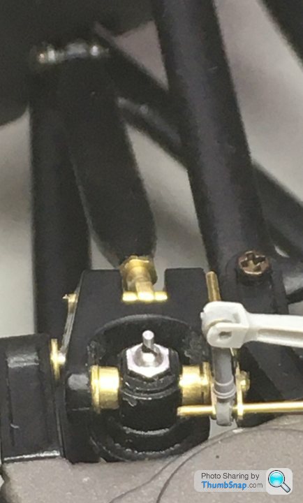
I’ve been addressing a few clunky details like the over-long screws that hold the wishbones and associated brackets together. My plan is to cut them to length, sand the heads down to the absolute minimum, then stick fastener heads on top of them:
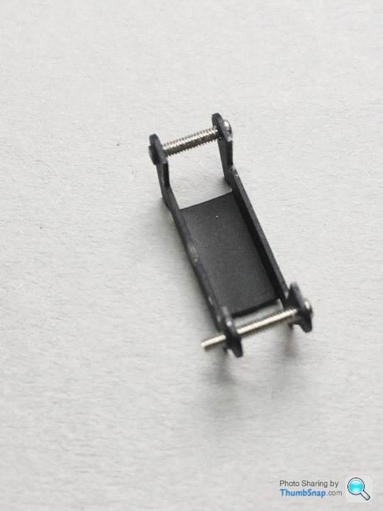
This is the rear lower mount for the wishbone and track control arm. I’ve cut some heat shrink tube to cover the exposed central threads on final assembly.
Also the anti-roll bar; I used Araldite to secure in the right orientation, then put Milliput around the joints to represent the dressed fillet welds of the real one:
Did a guide coat of primer. I think it needs a bit more profiling, then it’ll be ready for some pale gold paint:
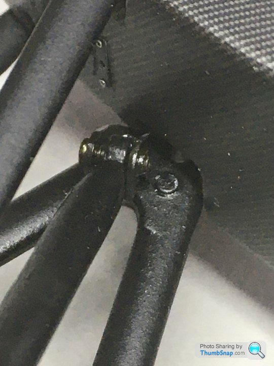
I didn’t intend to go down the front suspension rabbit hole just yet, especially since I’ve gone backwards on the rear of late. However, in the interests of getting things like suspension arms and roll bars the same colour, I opened the box. Although not included in the set, I wanted a robust and realistic enough way of attaching the brake lines to the wishbones. The originals had small saddles welded on, with a zip-tie used to secure. I approximated these with brass tube sections:
These were jigged in place with stainless wire and tape, and cyano’d:
Worked fine:
Once finally in place, I’ll represent the zip ties with strips of matt black painted tape.
Also profiled the re-positioned pushrod mounts to match the wishbones a bit better, not that they are really visible once the uprights are fitted:
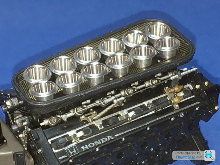
Just to keep this going I fitted the inlet trumpets. They were a real nightmare to align. I used standard Araldite to give some adjustment time, but even so, I’m not sure they’re 100% right even now.
I polished them up a bit with Autosol on a cotton bud:
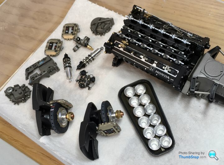
Couldn’t resist balancing a few bits of engine together to see how it looked:
I polished them up a bit with Autosol on a cotton bud:
Couldn’t resist balancing a few bits of engine together to see how it looked:
henryk001 said:
The detail of the engine build alone would be a lovely display in itself
To be honest it probably will be displayed on its own at this rate!Went to a Flying Boat museum/ “Heritage Centre” - whatever it’s called these days - yesterday to drop something off, and got inspired to build my 1:72 Airfix Swordfish and Matchbox Seafox (and a load of other stuff I saw they’d got built-up on display there).
new_bloke said:
dr_gn said:
To be honest it probably will be displayed on its own at this rate!
Went to a Flying Boat museum/ “Heritage Centre” - whatever it’s called these days - yesterday to drop something off, and got inspired to build my 1:72 Airfix Swordfish and Matchbox Seafox (and a load of other stuff I saw they’d got built-up on display there).
Where was that? Sounds interesting!Went to a Flying Boat museum/ “Heritage Centre” - whatever it’s called these days - yesterday to drop something off, and got inspired to build my 1:72 Airfix Swordfish and Matchbox Seafox (and a load of other stuff I saw they’d got built-up on display there).
https://www.sunderlandtrust.com/
I've got an old switch block that was used in the cockpits of Coastal Command Sunderland flying boats, and Lockheed Hudsons, so I thought I'd loan it to them. They are gradually restoring parts of a Mk1 Sunderland, that they are recovering from a wreck in the adjacent river, and putting them on display. We've been visiting for many years, and have watched the museum grow. It's only a small place, but they are enthusiastic and I think they deserve a bit of support.
ajprice said:
dr_gn, there was an MP4/6 at Goodwood, Retro Rides took some pictures https://www.instagram.com/p/CG0a46mnScM/?igshid=2f...
It had the body off, posting here as it might be some reference for something with your build.
Thanks very much for that AJP. It had the body off, posting here as it might be some reference for something with your build.
TBH, it's really more detail of the layup of the undertray I'm after. Long story, but I ended up in touch with the senior chassis designer on the MP4/6 project on Facebook (I'd posted an old 1989 Silverstone pits photo which had him in it on an FB group). Very friendly and helpful guy. There are lots of subtleties on the male-mould chassis layup that pretty much every modeller gets wrong. I want to get it right, but...it's not easy. I wrote a summary on the details on the F1M forum; I can re-post it here if anyone is interested.
As usual I've got sidetracked by other projects again, although I was really pleased with how it was going.
Gassing Station | Scale Models | Top of Page | What's New | My Stuff