Paper Ship: SMS Emden (1910), 1:250
Discussion


I was told to get some of this stuff for paper ship hulls (NOT detail parts):
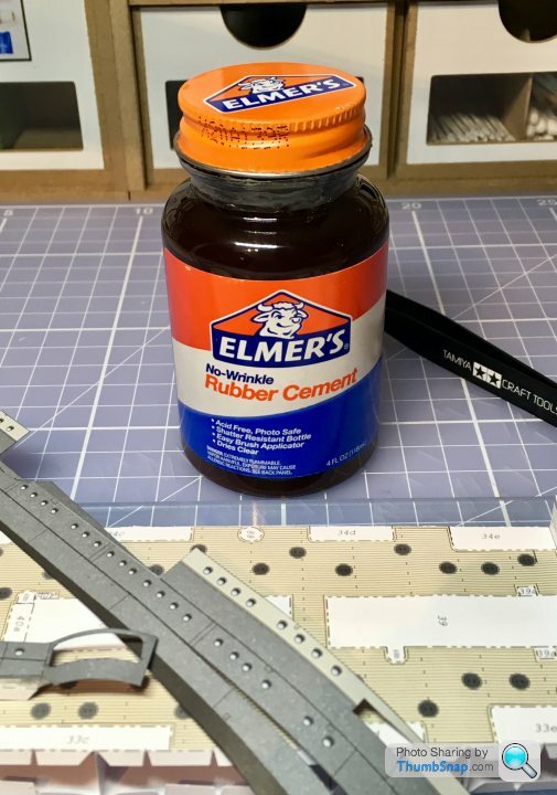
He should know his stuff - he designed the HMV Corvette.
First impressions weren’t too good - very gloopy, and fast drying similar to EvoStick contact adhesives. However, I used it on some test pieces, and it goes on ok with a cocktail stick. I’d describe it as resulting in a bond similar to a post-it note. It remains fully peelable for at least half an hour - which is perfect for positioning large parts. I think it may stay peelable, because excess can be rubbed off quite easily.
My plan is to position all the main hull sub-assemblies with Elmer’s, then wick PVA along all the external joints to make a final, stronger bond.
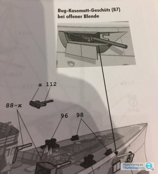
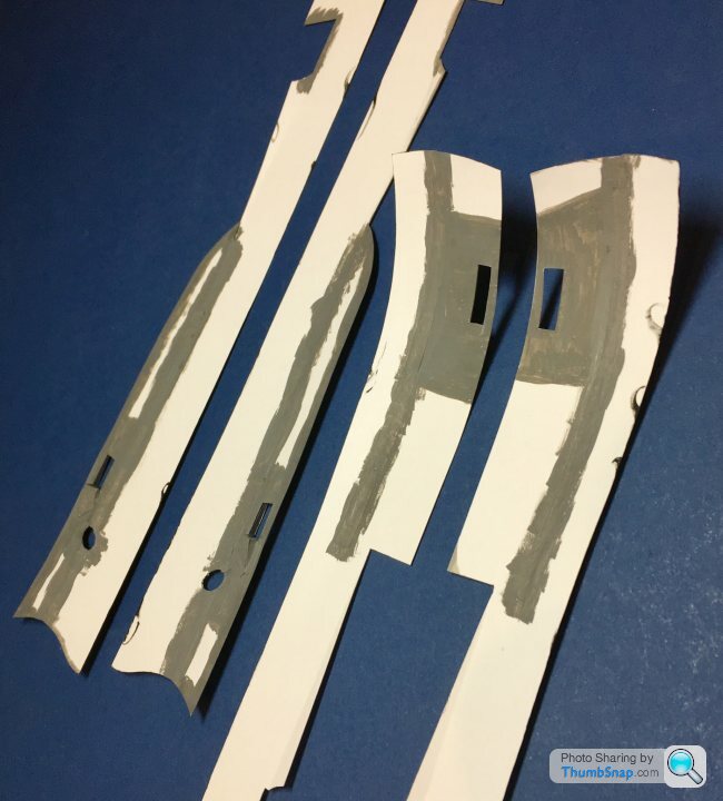
The bow casemate guns aren’t very clearly explained in the instructions. Some views show them closed up, with just the barrel showing:
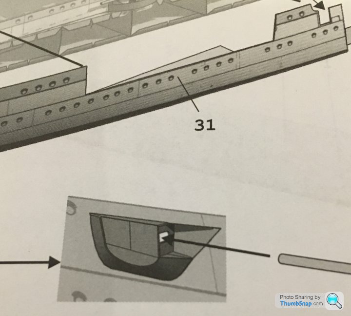
The alternative option is open, but apparently without the blister or covers:
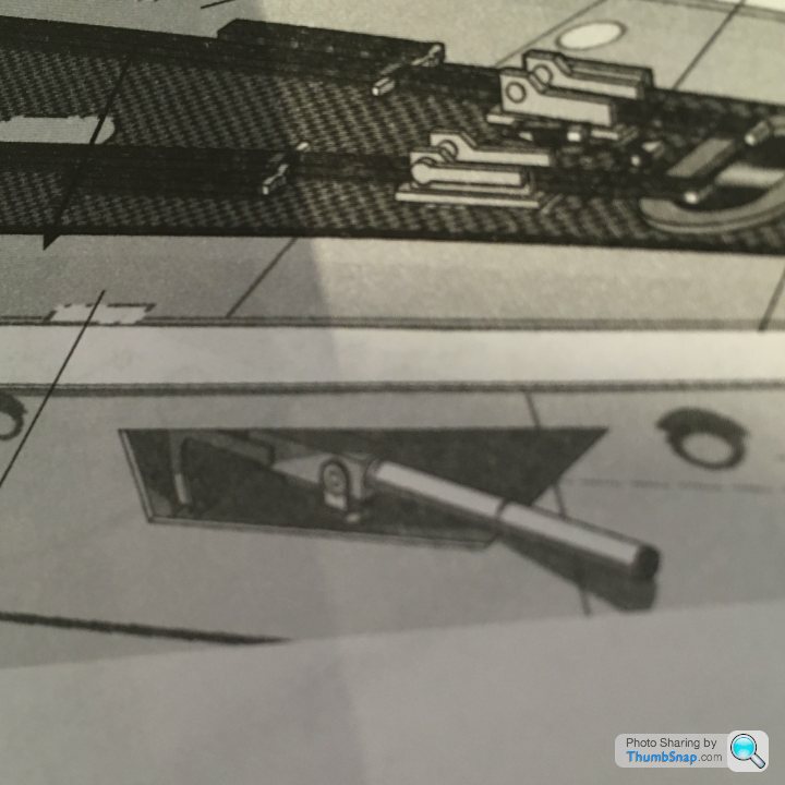
Only later is the open option revised to this:
I had a guess at this being right (although the slotted panel might have been intended to be flat to the hull:
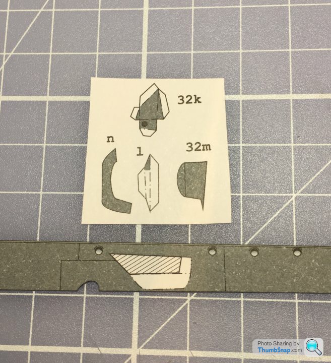
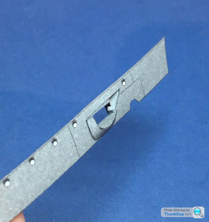
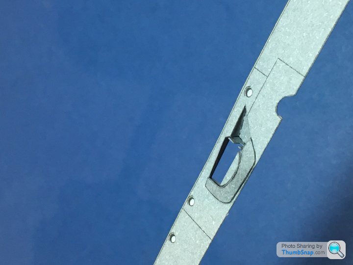
I doubt the inside will be visible, but I painted it anyway:
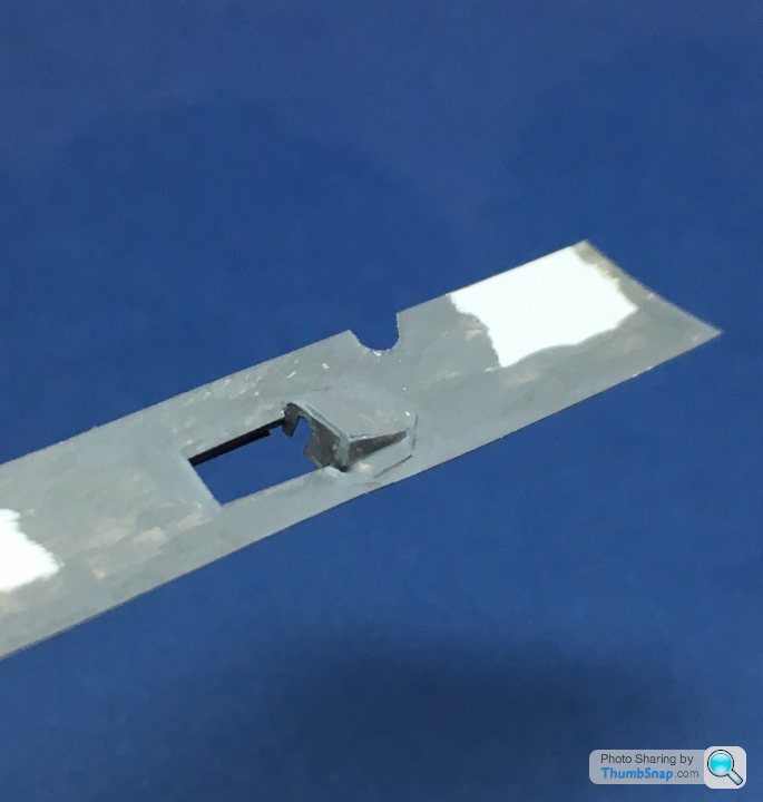
Part 31/32m needs to be split into 4 parts for the open option, yet most of the cut lines are missing. I made a best guess, so hopefully it will be ok.
I’ll add the open doors later.
The alternative option is open, but apparently without the blister or covers:
Only later is the open option revised to this:
I had a guess at this being right (although the slotted panel might have been intended to be flat to the hull:
I doubt the inside will be visible, but I painted it anyway:
Part 31/32m needs to be split into 4 parts for the open option, yet most of the cut lines are missing. I made a best guess, so hopefully it will be ok.
I’ll add the open doors later.
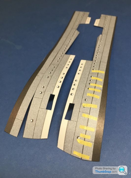
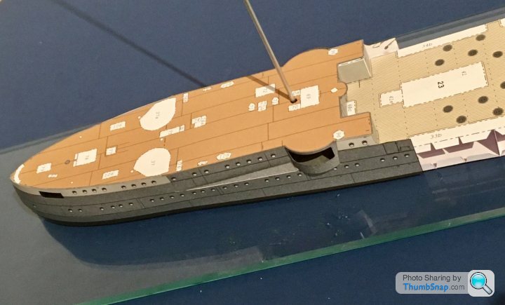
The masts on this one are huge, and there’s plenty of rigging between and around them. I’ve modified the model slightly by bonding these aluminium tubes into the hull:
They’ll form a much stronger location for the masts than the paper deck. I’ll bond a wire spigot into the bottom half of each tubular paper mast, and Araldite it into the aluminium sockets near the end of the build. None of the aluminium or wire will be visible once complete.
They’ll form a much stronger location for the masts than the paper deck. I’ll bond a wire spigot into the bottom half of each tubular paper mast, and Araldite it into the aluminium sockets near the end of the build. None of the aluminium or wire will be visible once complete.
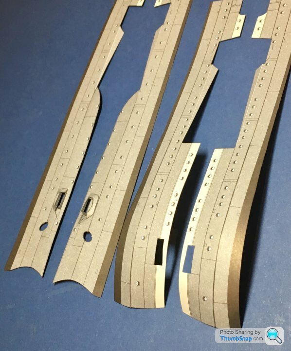
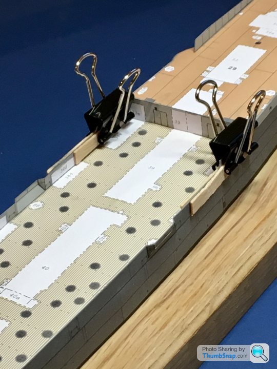
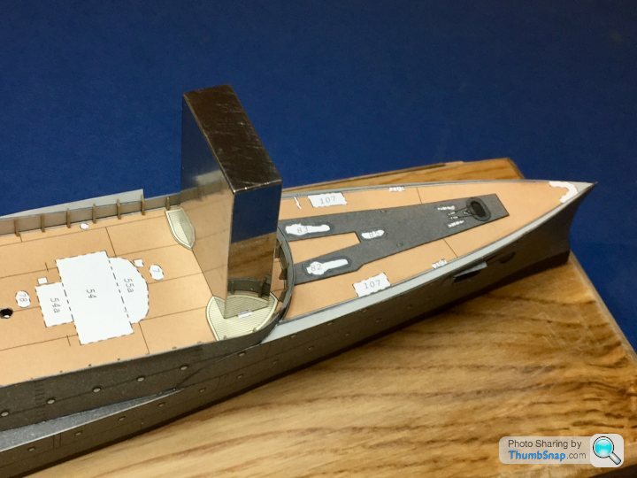
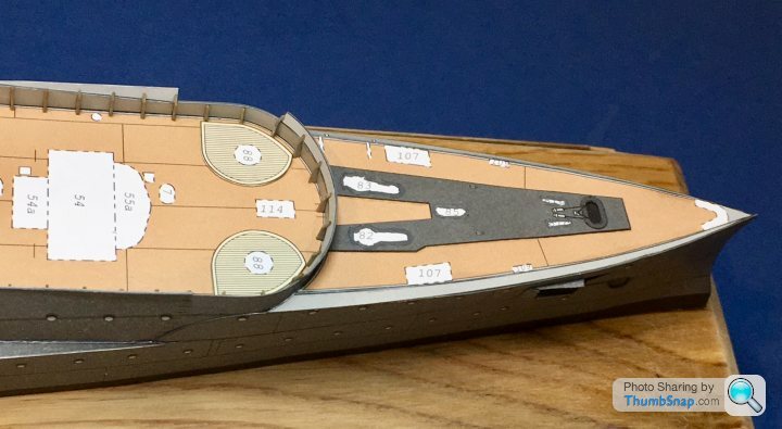
Now things get tricky. There are 4 stern panels and the deck, all of which need assembling to pretty close tolerances if there are to be no gaps. The areas around the casemate guns comprise curves and angled sections, all of which need to mate pretty much perfectly. The stern sides also have cuts in them which when closed, form an angled, curved profile. Starting with these, after painting all exposed edges, I tacked them in place with Tamiya tape:
Then painted pva along the joints, backed up with thin tracing paper to form a shear joint rather than an edge joint:
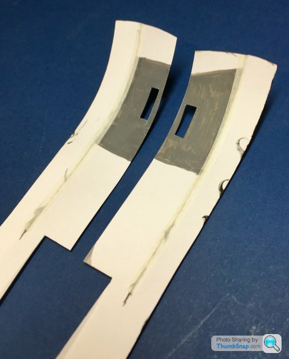
Then painted the back to make any small gaps opaque. The upper and lower bow sides were joined in the same manner:
This results in - pretty much - perfect joins, with no excess glue on the outside:
On to the casemate panels:
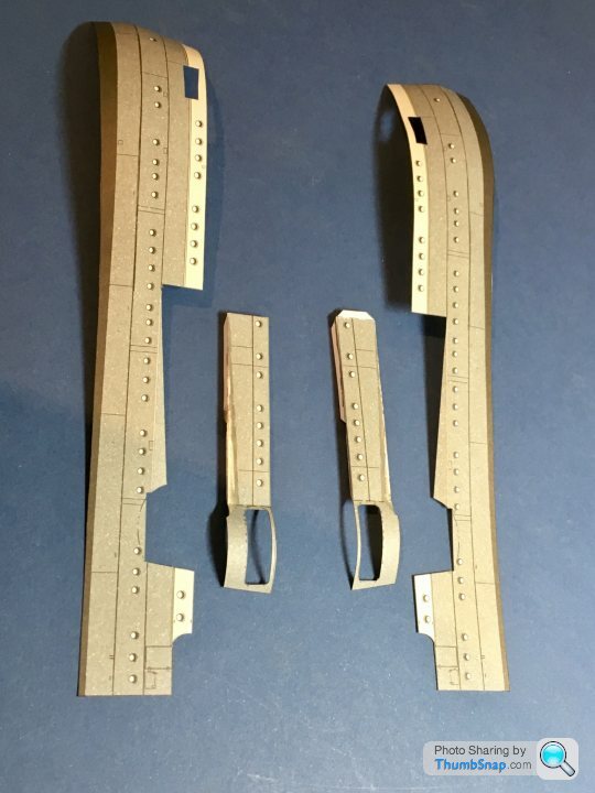
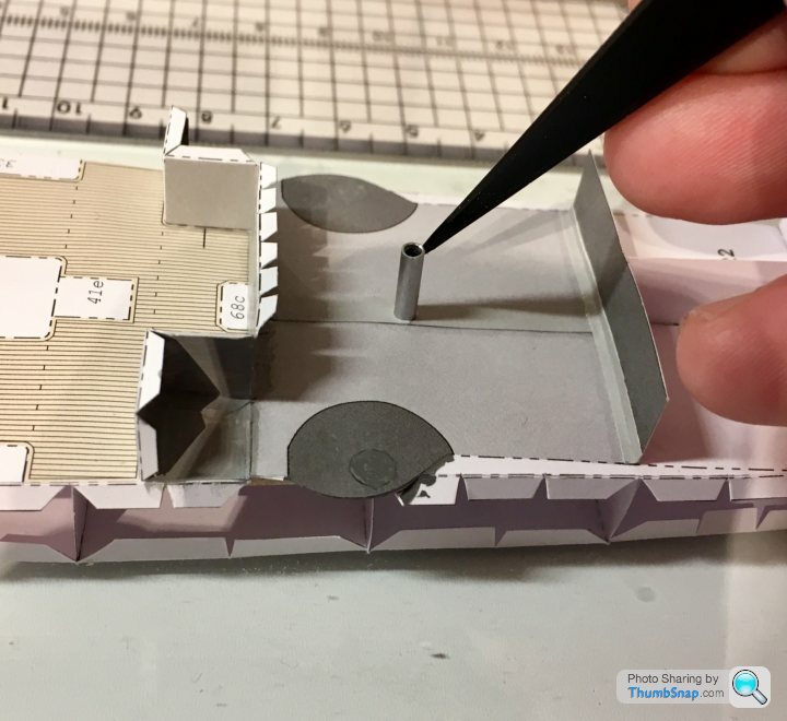
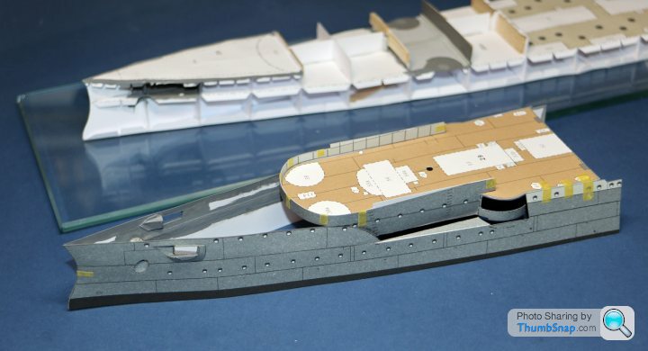
The ends were trimmed to the right length, and joined to the stern sides as above. Then, the two sub-assemblies were fitted to the rear deck using Elmer’s glue, which allowed adjustment to suit the casemate bulges. PVA was then brushed along the inside edges of the hull-deck interface. This formed a shell structure:
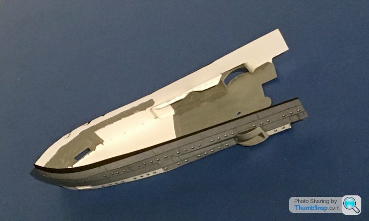
I opted for this shell method because it simplifies the critical, and very difficult, hull-deck joint, allowing access to the inside and outside for adjustments and application of glue.
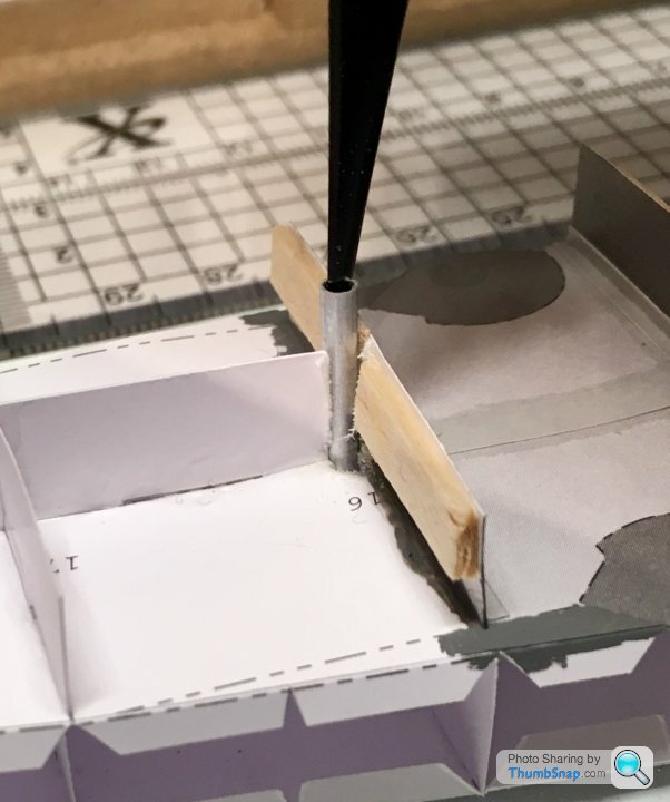
The insides will be finally painted dark grey in case anything is visible from the gun ports (unlikely, but possible). The shell fitted nicely to the stern sub-structure, at least as a test-fit. The aluminium rod represents the mast spigot, which lines up nicely with its previously fitted socket.
Next, the bow shell structure.
Then painted pva along the joints, backed up with thin tracing paper to form a shear joint rather than an edge joint:
Then painted the back to make any small gaps opaque. The upper and lower bow sides were joined in the same manner:
This results in - pretty much - perfect joins, with no excess glue on the outside:
On to the casemate panels:
The ends were trimmed to the right length, and joined to the stern sides as above. Then, the two sub-assemblies were fitted to the rear deck using Elmer’s glue, which allowed adjustment to suit the casemate bulges. PVA was then brushed along the inside edges of the hull-deck interface. This formed a shell structure:
I opted for this shell method because it simplifies the critical, and very difficult, hull-deck joint, allowing access to the inside and outside for adjustments and application of glue.
The insides will be finally painted dark grey in case anything is visible from the gun ports (unlikely, but possible). The shell fitted nicely to the stern sub-structure, at least as a test-fit. The aluminium rod represents the mast spigot, which lines up nicely with its previously fitted socket.
Next, the bow shell structure.
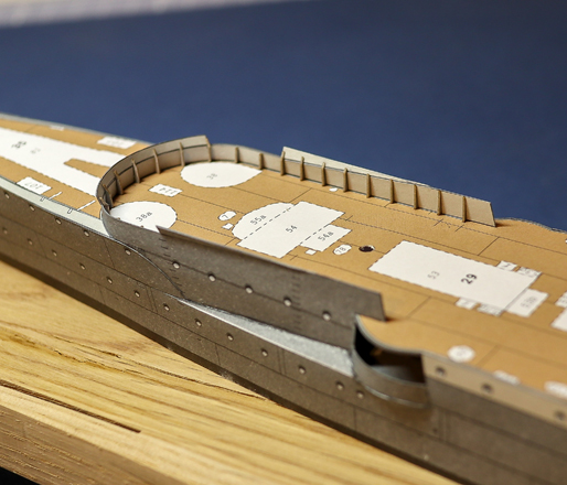
On to the bow section, and it's even more complex than the stern, being linked side-to side with a curved upper deck bulkhead:
I'm in the process of temporarily taping, then tacking various key points with PVA. Once complete, It'll hopefully slip over the substructre in the same way as the stern, leaving just the flat sides to add.
I'm in the process of temporarily taping, then tacking various key points with PVA. Once complete, It'll hopefully slip over the substructre in the same way as the stern, leaving just the flat sides to add.
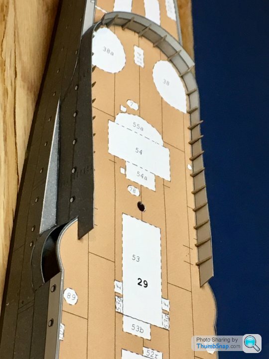
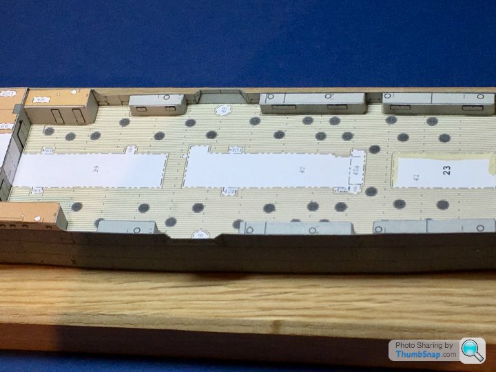
One of the many things that can ruin the look of a paper model are the chain-dot lines marking the white footprints of structures, or external cut lines. No idea why designers do it, since any inevitable misalignment or less than perfect cut leaves an unsightly signature of white lines and black dotted ink. It would be far better to use solid colour and lines throughout. After all it’s always pretty obvious which side a part need scoring on.
Anyway I began the tedious process of mixing paint to match the surrounding areas and blocking out the lines for the foredeck chain plates and gun platforms:
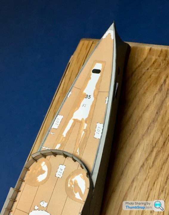
Parts glued down after colouring their white edges. I often use an old 1” slip gauge to hold the top surfaces of plate parts flat while letting blobs of PVA act as liquid levelling shim:
Another small step complete:
Anyway I began the tedious process of mixing paint to match the surrounding areas and blocking out the lines for the foredeck chain plates and gun platforms:
Parts glued down after colouring their white edges. I often use an old 1” slip gauge to hold the top surfaces of plate parts flat while letting blobs of PVA act as liquid levelling shim:
Another small step complete:
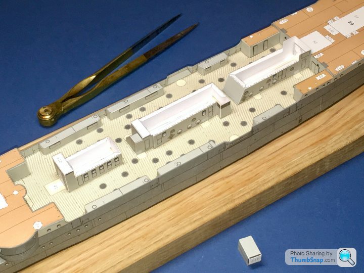
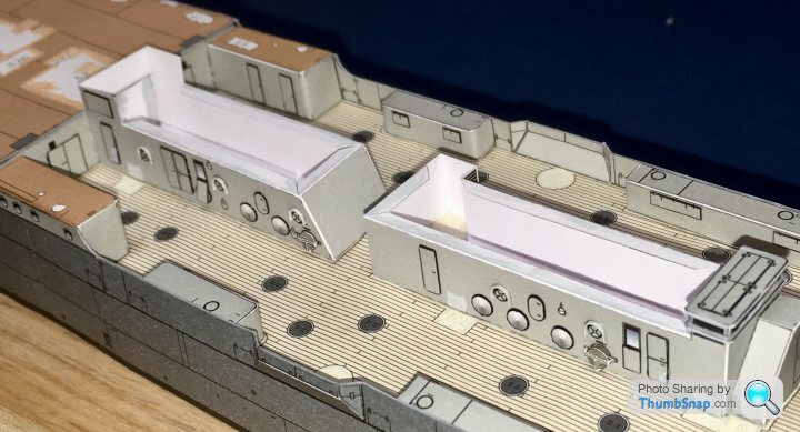
Deck side houses fitted along with their door doublers:
I noted previously that the hull sides tapered inwards slightly, and wondered at the time if I’d made an error when fitting the sides. I had seen this in older, wooden warships, but not that I could remember on iron ones. I was pleased to find that the deck side house ends were also angled to match, so it appears hull construction was correct after all. Phew.
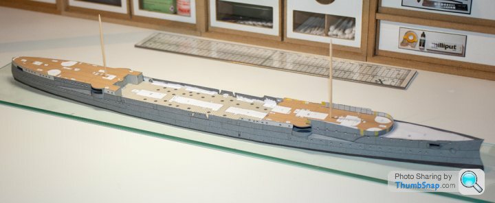
That completes what I’d call the main hull assembly. Next will be superstructure.
I noted previously that the hull sides tapered inwards slightly, and wondered at the time if I’d made an error when fitting the sides. I had seen this in older, wooden warships, but not that I could remember on iron ones. I was pleased to find that the deck side house ends were also angled to match, so it appears hull construction was correct after all. Phew.
That completes what I’d call the main hull assembly. Next will be superstructure.
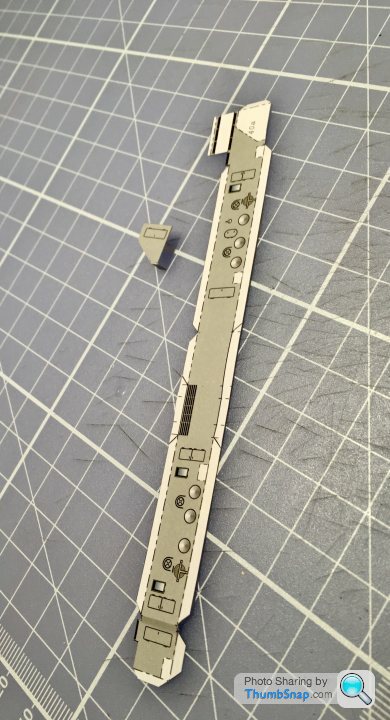
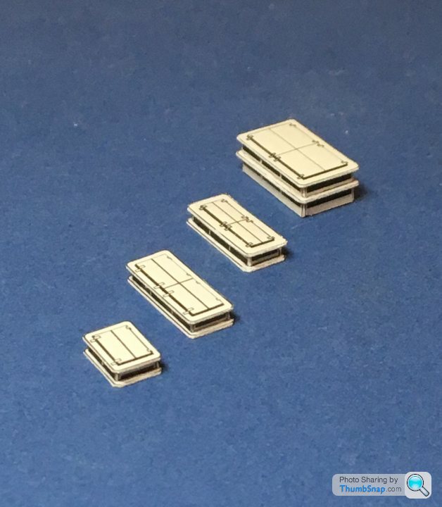
I think these pillars with domed covers on top may be range finders or something like that. The diagram appears to show an extra piece for the covers. I assume they just meet in the middle, and fold down on each side:
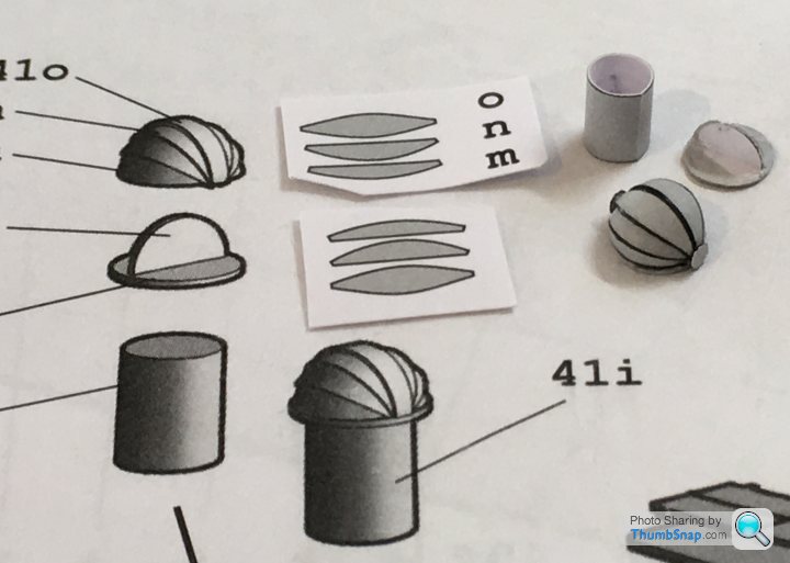
I added some pivot covers from punched paper to neaten things up a bit.
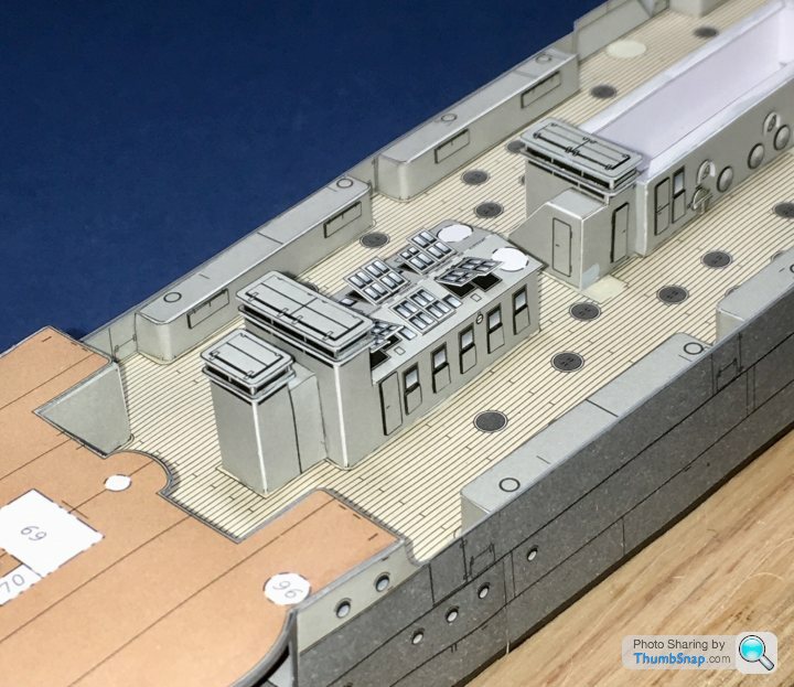
The pillars are chamfered at their bases to fit the pitched cabin roof. I jigged them to be vertical and level with a block of aluminium:
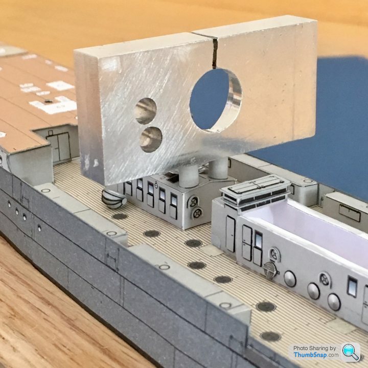
Another small step completed:
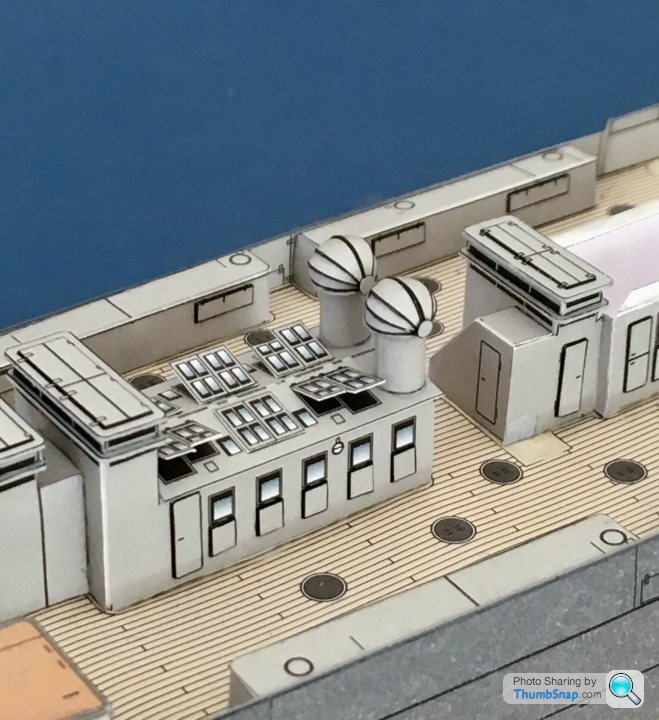
I added some pivot covers from punched paper to neaten things up a bit.
The pillars are chamfered at their bases to fit the pitched cabin roof. I jigged them to be vertical and level with a block of aluminium:
Another small step completed:
I think they may be engine room ventilators; I was curious so Googled and found this plan:
http://virtualdockyard.co.uk/0-PLANS-PAGES/EMDEN-2...
http://virtualdockyard.co.uk/0-PLANS-PAGES/EMDEN-2...
Gassing Station | Scale Models | Top of Page | What's New | My Stuff