Paper Ship: SMS Emden (1910), 1:250
Discussion


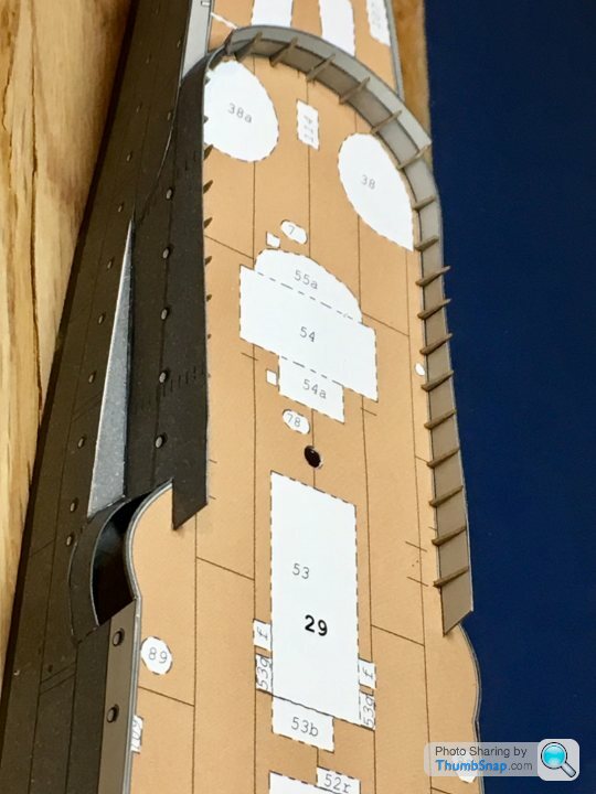
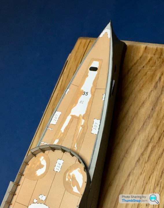
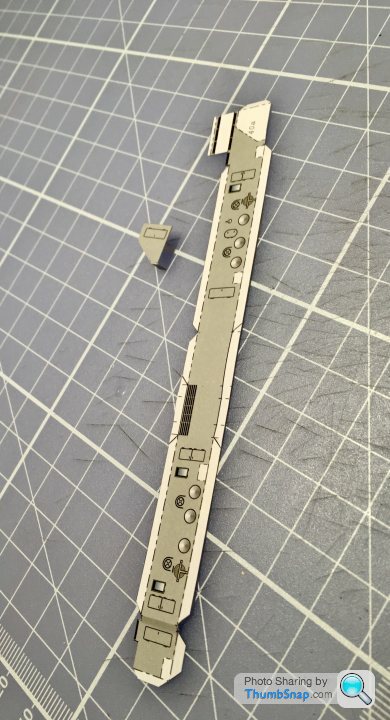
One of the many things that can ruin the look of a paper model are the chain-dot lines marking the white footprints of structures, or external cut lines. No idea why designers do it, since any inevitable misalignment or less than perfect cut leaves an unsightly signature of white lines and black dotted ink. It would be far better to use solid colour and lines throughout. After all it’s always pretty obvious which side a part need scoring on.
Anyway I began the tedious process of mixing paint to match the surrounding areas and blocking out the lines for the foredeck chain plates and gun platforms:
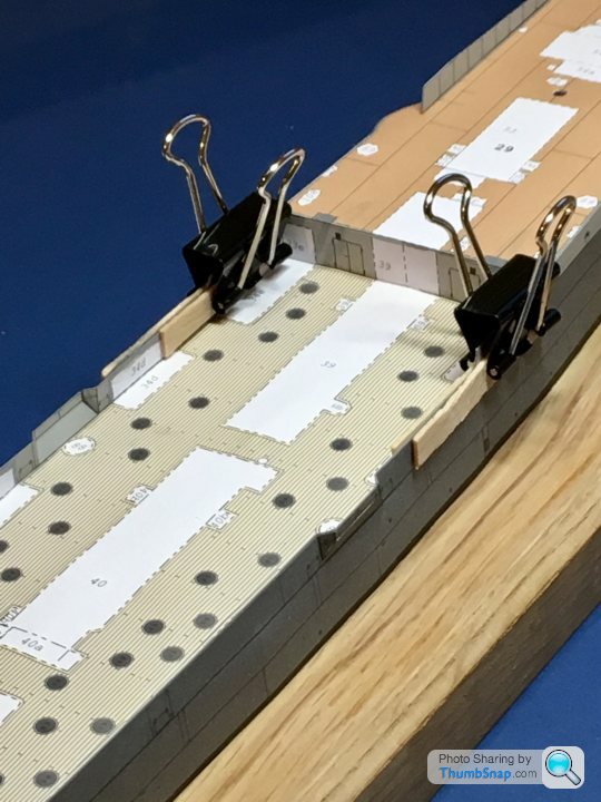
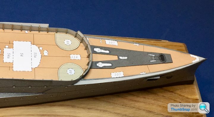
Parts glued down after colouring their white edges. I often use an old 1” slip gauge to hold the top surfaces of plate parts flat while letting blobs of PVA act as liquid levelling shim:
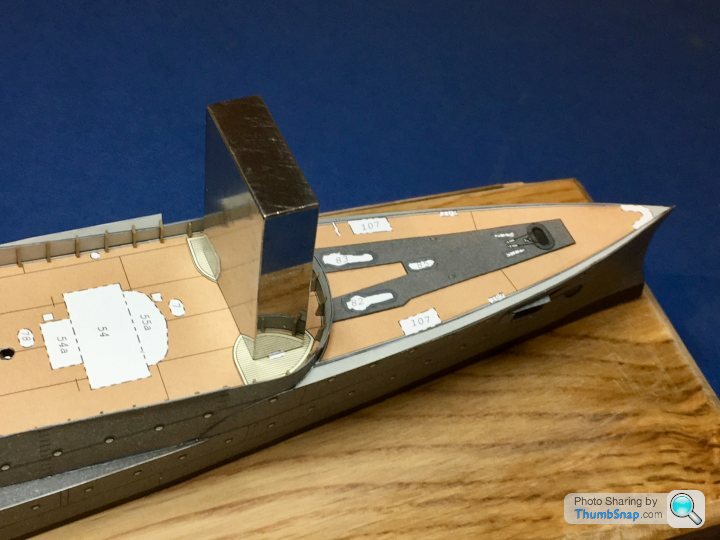
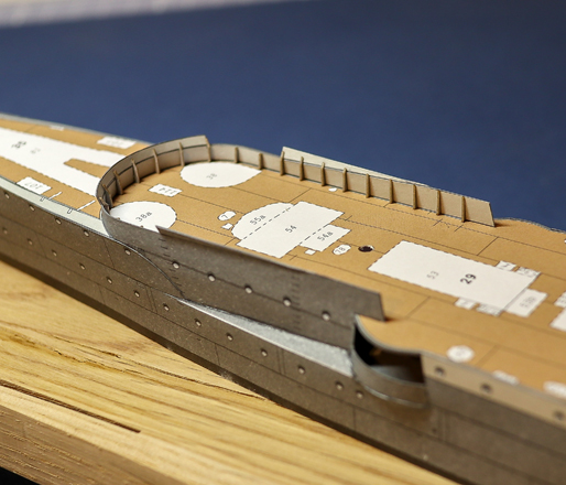
Another small step complete:
Anyway I began the tedious process of mixing paint to match the surrounding areas and blocking out the lines for the foredeck chain plates and gun platforms:
Parts glued down after colouring their white edges. I often use an old 1” slip gauge to hold the top surfaces of plate parts flat while letting blobs of PVA act as liquid levelling shim:
Another small step complete:
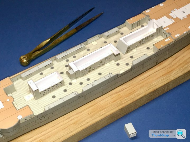
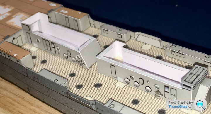
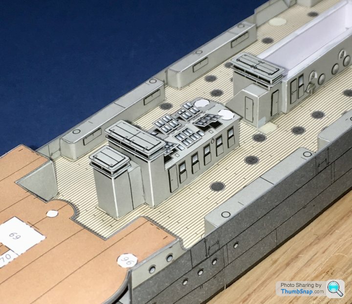
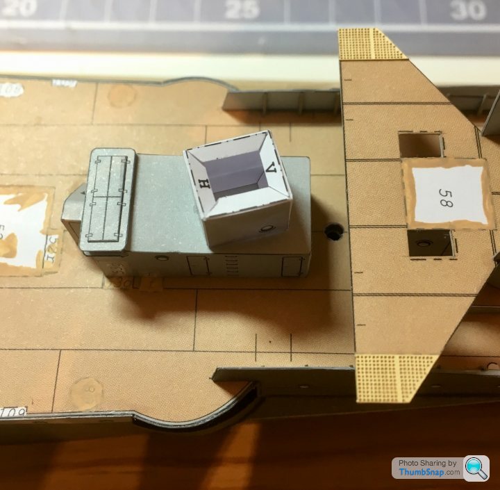
Deck side houses fitted along with their door doublers:
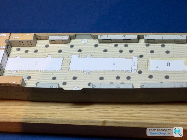
I noted previously that the hull sides tapered inwards slightly, and wondered at the time if I’d made an error when fitting the sides. I had seen this in older, wooden warships, but not that I could remember on iron ones. I was pleased to find that the deck side house ends were also angled to match, so it appears hull construction was correct after all. Phew.
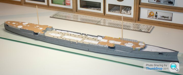
That completes what I’d call the main hull assembly. Next will be superstructure.
I noted previously that the hull sides tapered inwards slightly, and wondered at the time if I’d made an error when fitting the sides. I had seen this in older, wooden warships, but not that I could remember on iron ones. I was pleased to find that the deck side house ends were also angled to match, so it appears hull construction was correct after all. Phew.
That completes what I’d call the main hull assembly. Next will be superstructure.
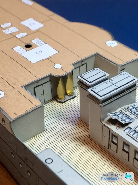
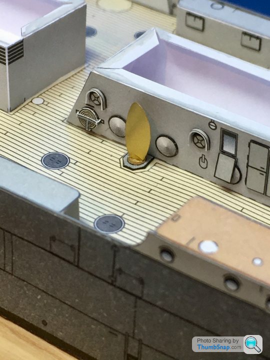
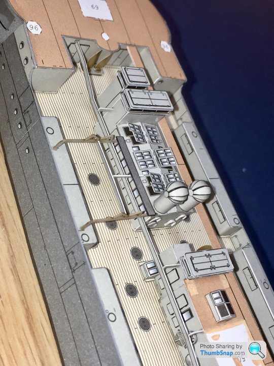
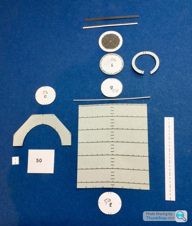
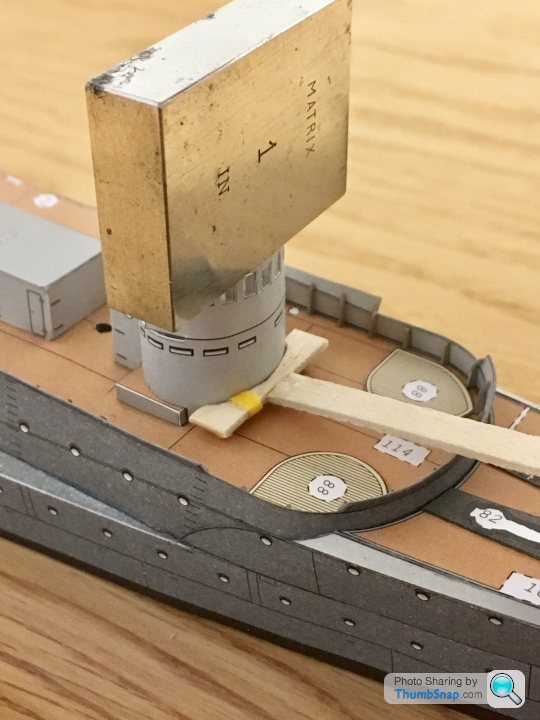
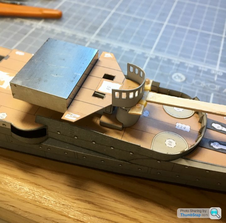
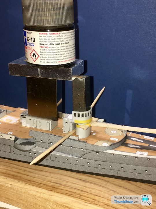
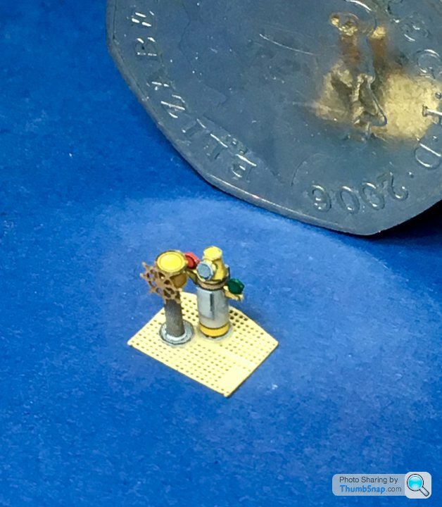
I think these pillars with domed covers on top may be range finders or something like that. The diagram appears to show an extra piece for the covers. I assume they just meet in the middle, and fold down on each side:
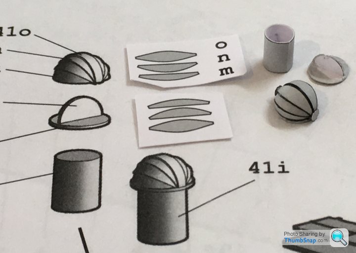
I added some pivot covers from punched paper to neaten things up a bit.
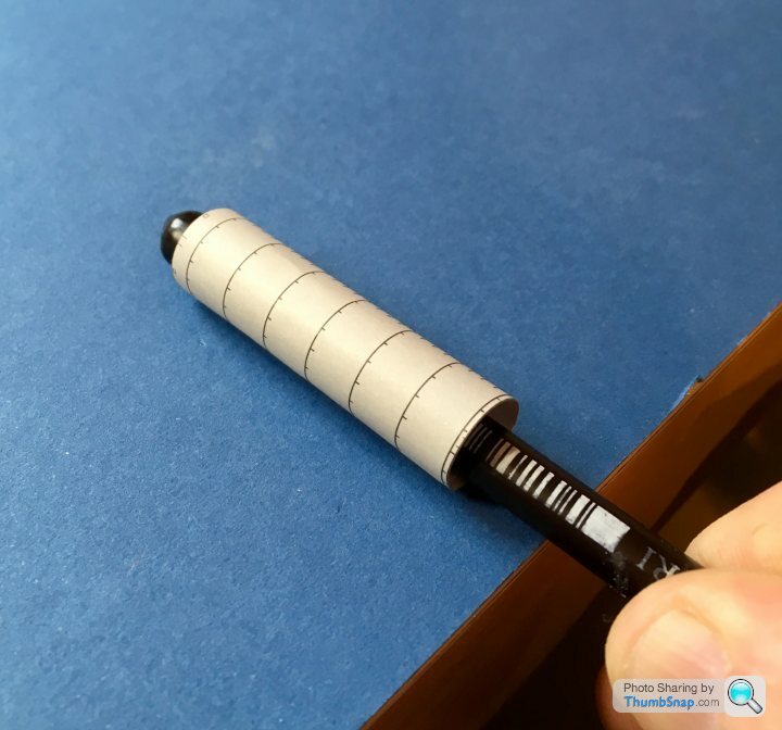
The pillars are chamfered at their bases to fit the pitched cabin roof. I jigged them to be vertical and level with a block of aluminium:
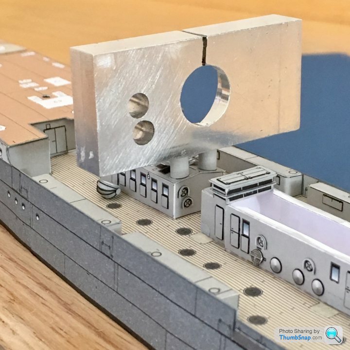
Another small step completed:
I added some pivot covers from punched paper to neaten things up a bit.
The pillars are chamfered at their bases to fit the pitched cabin roof. I jigged them to be vertical and level with a block of aluminium:
Another small step completed:
Riley Blue said:
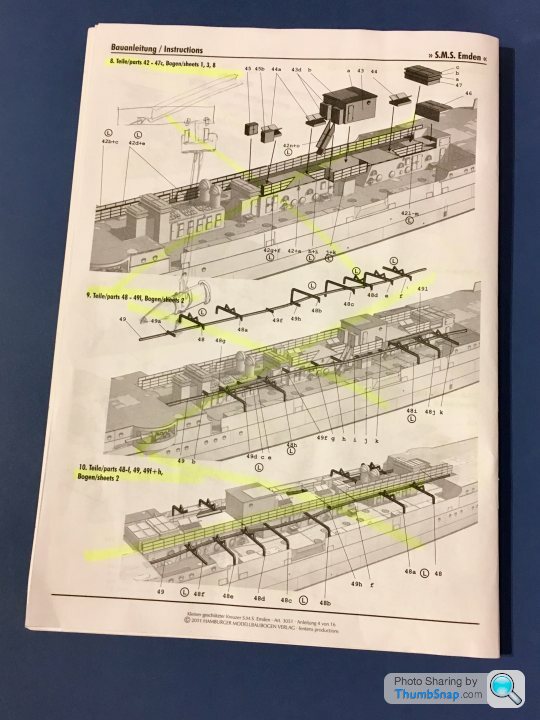
I think they may be engine room ventilators; I was curious so Googled and found this plan:
http://virtualdockyard.co.uk/0-PLANS-PAGES/EMDEN-2...
That's a good drawing - thanks, I'll nick that one!http://virtualdockyard.co.uk/0-PLANS-PAGES/EMDEN-2...
Looks like the rectangular things are definitely ventilator inlets, but the domed ones are outlets? But why cover them? I'm sure I've seen them on later battleships as drop-down covers for some instrument or other.
Drawing also confirms the hull sides slope inwards.
Cheers.
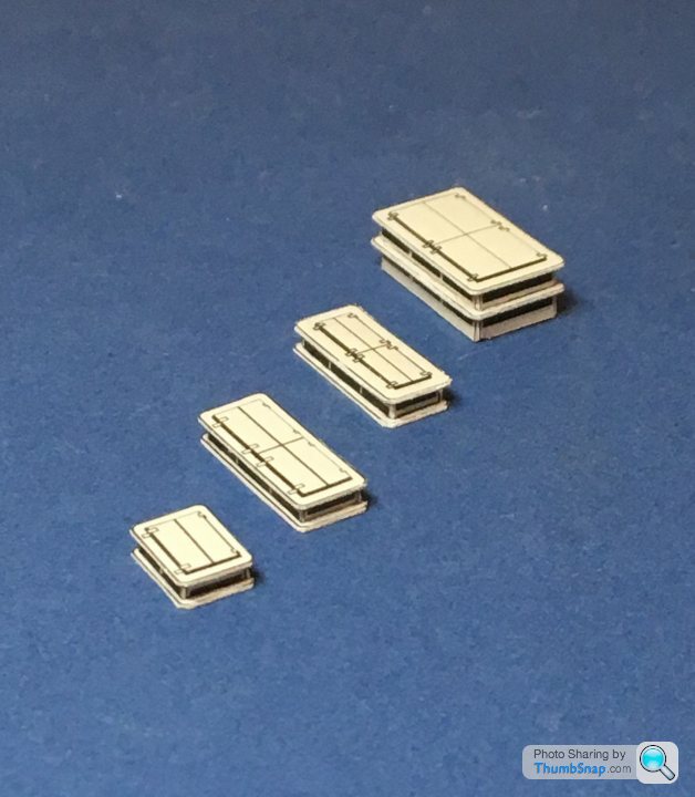
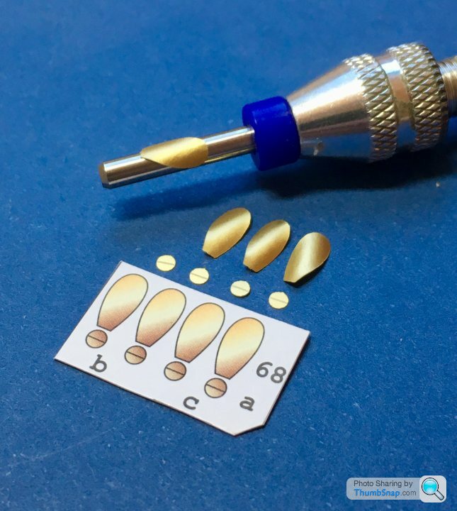
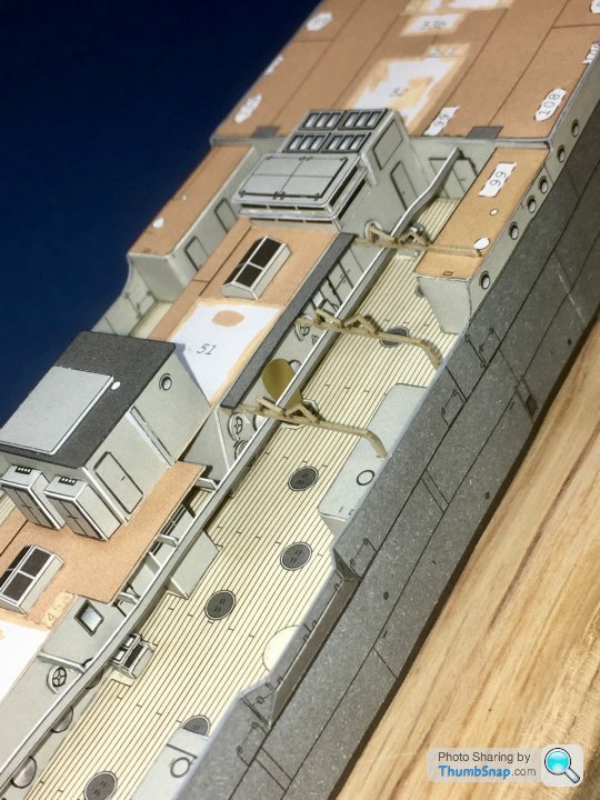
A really nice touch is the spare screw blades and ship’s bell in laser-cut brass metallised paper. They look much better than the paper versions. I gave them some camber around a drill shank, and made two left-handed and two right-handed:
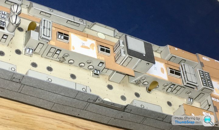
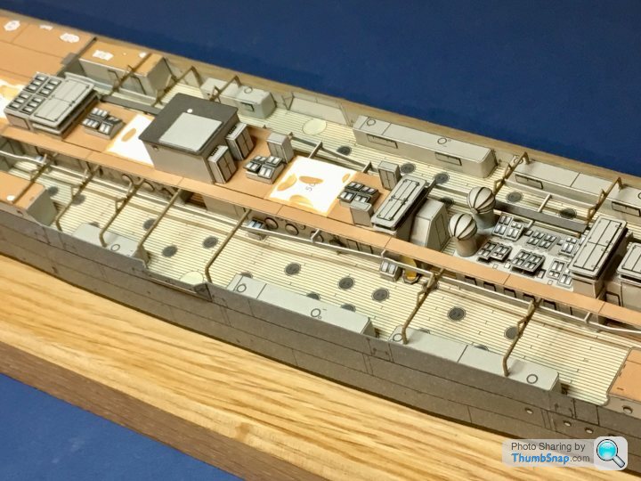
Here they are fitted to the deck:
So that completes step 7.
Here they are fitted to the deck:
So that completes step 7.
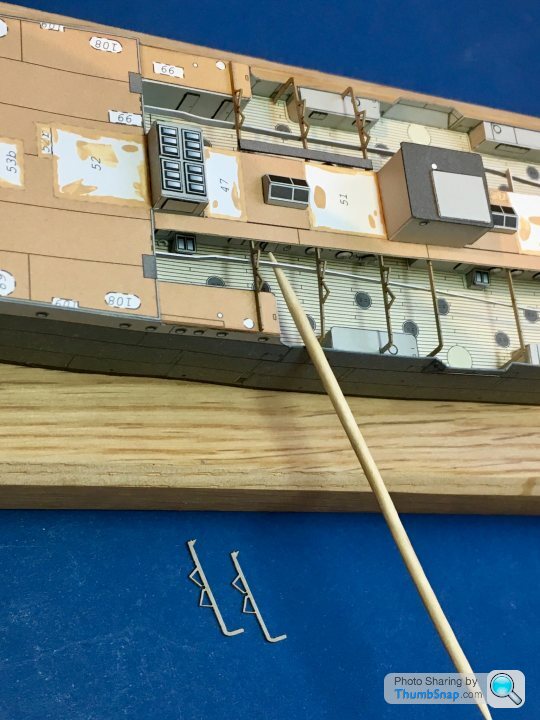
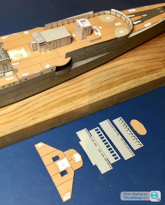
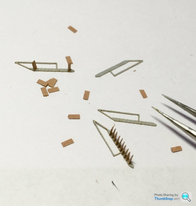
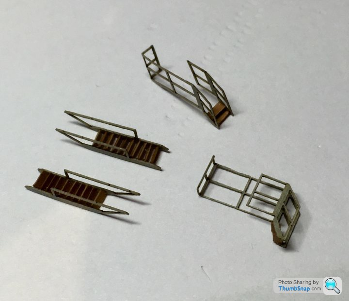
Next up is bending and installing this insanely difficult starboard longitudinal rail - presumably for a pulley block to move shells etc. around the deck:
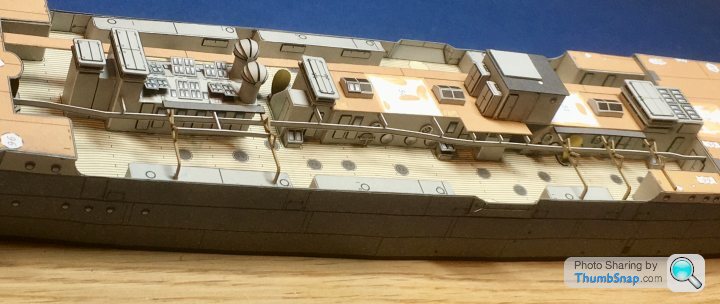
It’s suspended from a series of horizontal cantelever beams and the lifeboat supports:
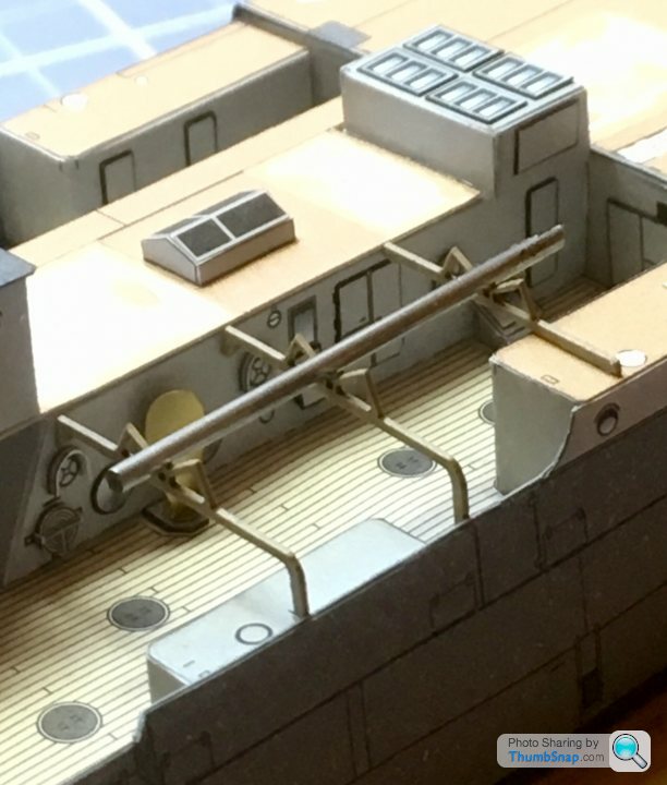
I used a short piece of rod to ensure alignment of those.
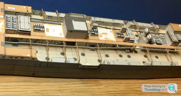
Now for the other side...
It’s suspended from a series of horizontal cantelever beams and the lifeboat supports:
I used a short piece of rod to ensure alignment of those.
Now for the other side...
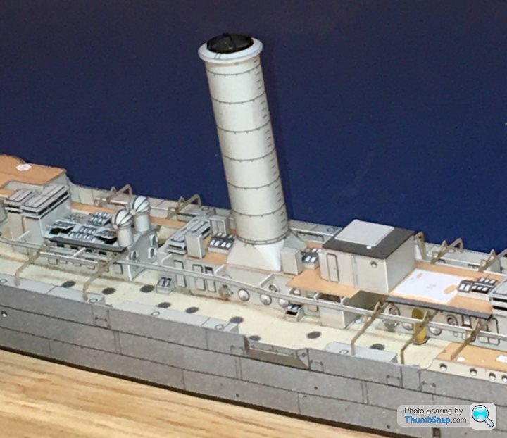
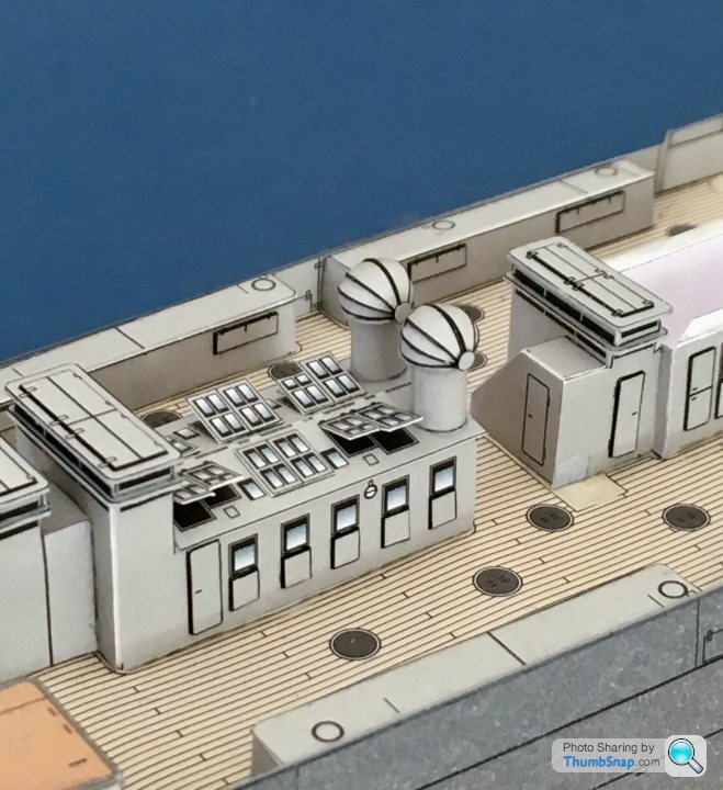
Did some more work on the front deck-houses, and the beginnings of the bridge structure:
The deck is cambered, and slopes up towards the bows, so I tried to get the tops of the structures as horizontal as possible using a steel rule balanced in the roofs, and another Perspex rule to sight against:
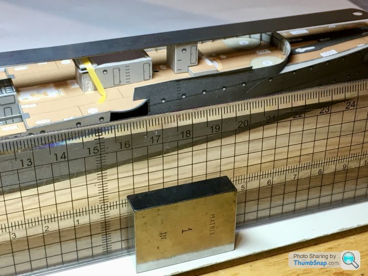
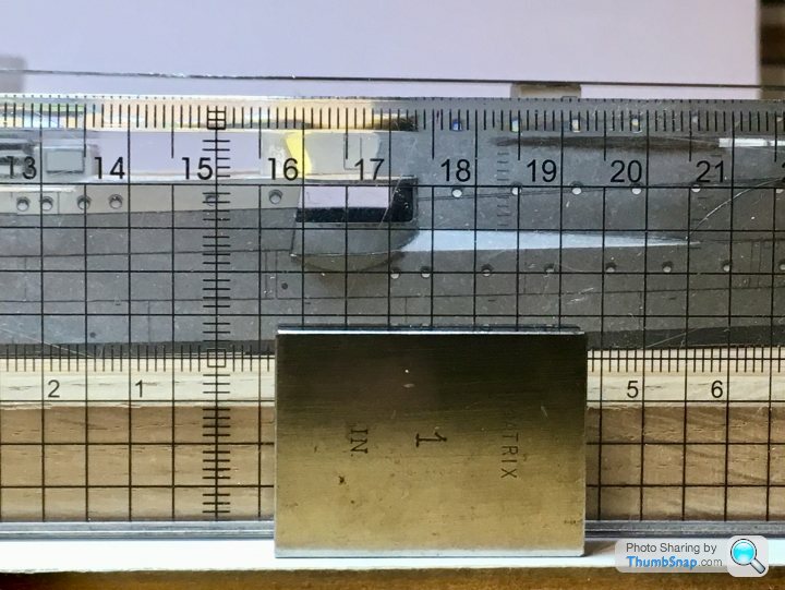
This way, I can keep everything within the levelling limits of blobs of PVA as I build the structures up.
The deck is cambered, and slopes up towards the bows, so I tried to get the tops of the structures as horizontal as possible using a steel rule balanced in the roofs, and another Perspex rule to sight against:
This way, I can keep everything within the levelling limits of blobs of PVA as I build the structures up.
On to the main bridge structure. It’s a bit of an animal. The upper and lower surfaces are curved, and double skinned. I opted to glaze the wheelhouse windows with thin acetate, so they are effectively triple skinned. After carefully cutting out the printed windows from both skins, I sandwiched the acetate. This made forming the curves more difficult. The lower curves are defined by a deck former, and the mid deck. I made a wooden jig to hold the curved bits in place while the PVA set:
Same with the mid deck, but this also needed weighting to the lower deck house:
The reason I opted to glaze the wheel house, was that the wheel and binnacle are in there, and partially visible:
With these in place, the upper deck house could be fitted (front and rear is indicated on the tabs). And yes, the main mast is going to be very tight fit in there...
Then the roof piece could be fitted. I wasn’t too happy with the fit around the join, nor with the design of the mid deck join - there’s a slice of deck visible where it should be covered. I opted to add two thin bands of grey paper to neaten these up. Call it a bodge, or modeller’s license, but either way it looks better to my eyes:
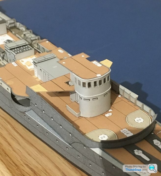
Still a load more detail to go onto the bridge, but at least the main bits are there and aligned.
Same with the mid deck, but this also needed weighting to the lower deck house:
The reason I opted to glaze the wheel house, was that the wheel and binnacle are in there, and partially visible:
With these in place, the upper deck house could be fitted (front and rear is indicated on the tabs). And yes, the main mast is going to be very tight fit in there...
Then the roof piece could be fitted. I wasn’t too happy with the fit around the join, nor with the design of the mid deck join - there’s a slice of deck visible where it should be covered. I opted to add two thin bands of grey paper to neaten these up. Call it a bodge, or modeller’s license, but either way it looks better to my eyes:
Still a load more detail to go onto the bridge, but at least the main bits are there and aligned.
Edited by dr_gn on Sunday 9th September 22:46
Gassing Station | Scale Models | Top of Page | What's New | My Stuff