Revell Visible V8 Engine Rebuild/Upgrade
Discussion


Ennisdavis said:
Even with the better fitting lifters, there are no cam bearings so the cam flops around and jambs the lifters. Any fixes here?
That shouldn't be much of a problem if the cam is straight.The valve springs are weak, and even if they deflected the cam excessively, this should be limited by the clear plastic semi-circular cut-outs underneath the middle cam "bearing" bosses.
Of course, if the tappet guides aren't a good fit, and they begin to jam, this will cause much more bending load on the cam.
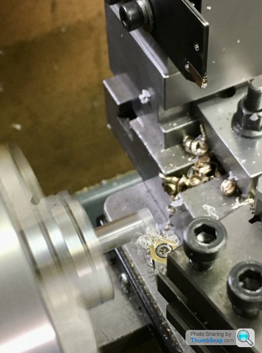
I might have another look at the guides tomorrow. Now I've got some experience of accurate lathe turning I might be able to come up with something.
Must admit I lost interest in this after embarking on ‘proper’ model engineering last year. The tolerances and compromises in producing a 1960’s era injection-moulded working engine add up to a not particularly great model.
Anyway, it needs finishing, so:
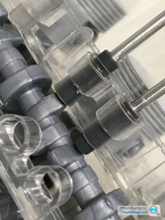
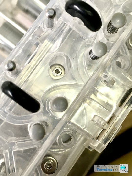
Made some clear plastic inserts for the cam followers. These are a better fit on the newly turned followers, and more importantly, give a longer sliding contact area. This reduces the jamming effect of the originals. I machined them to a top-hat section, and they’re PVA’d in place:
I’d wanted to use tappet adjusters on the rockers, like on a real pushrod engine, but the alignmemts were too far off. I still needed some way of taking up the rattly free play in the system though, so opted to drill the aluminium pushrods and install domed head screws:
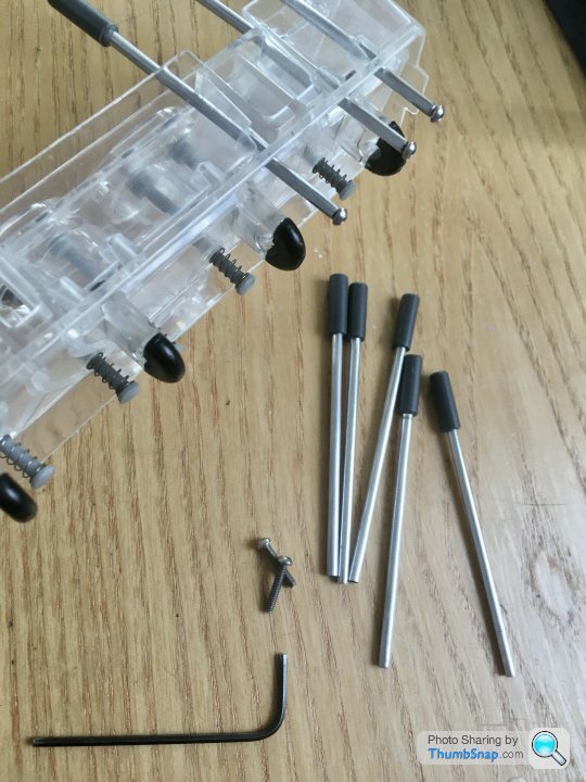
These allow everything to be closed up after assembly.
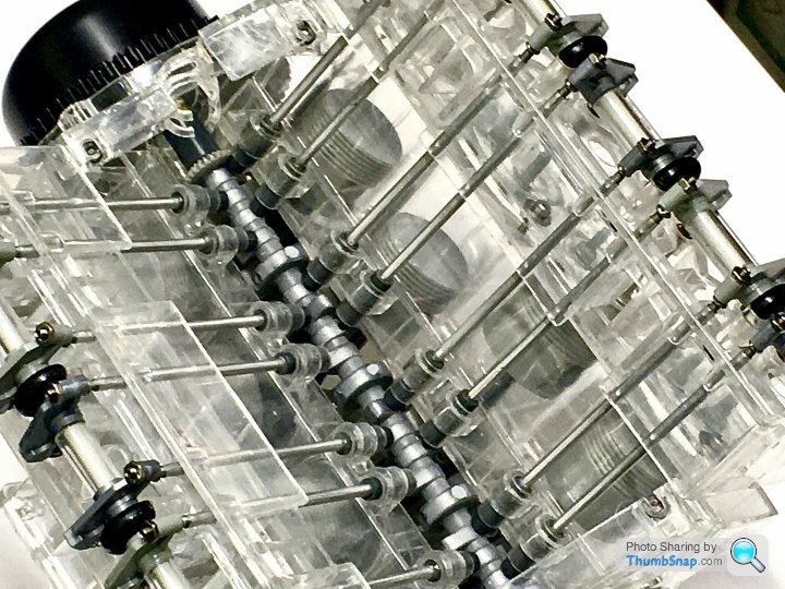
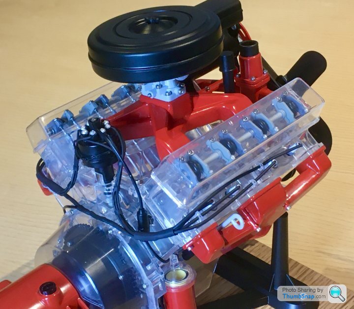
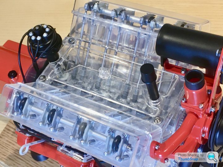
I used some knitting needles off EBay for the rocker shafts. They’re anodised and give a nice smooth action for the rockers without lubrication. The ends were drilled and tapped for retaining screws and washers:
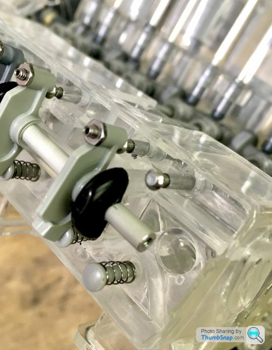
Also visible are the dummy tappet adjusters and lock-nuts. I was reluctant to add these, but the rockers assembly is the most visible part of the model when operating, and it needed a bit more visual interest.
I also found the two original cylinder head retaining screws per side weren’t enough. The heads would tilt under the action of the valves. I added three more by drilling the heads to the inside of the V:
Like all other simulated bolt heads, I replaced the sump fasteners with real screws, and made a brass sump plug:
The weakest point of the model is the distributor bevel gear drive. I’m still refining this, using improved location for the gears, and using a lightly sprung-loaded meshing method. It works, but I’m unsure how long it will keep the correct timing. More of that some other time.
Current progress:
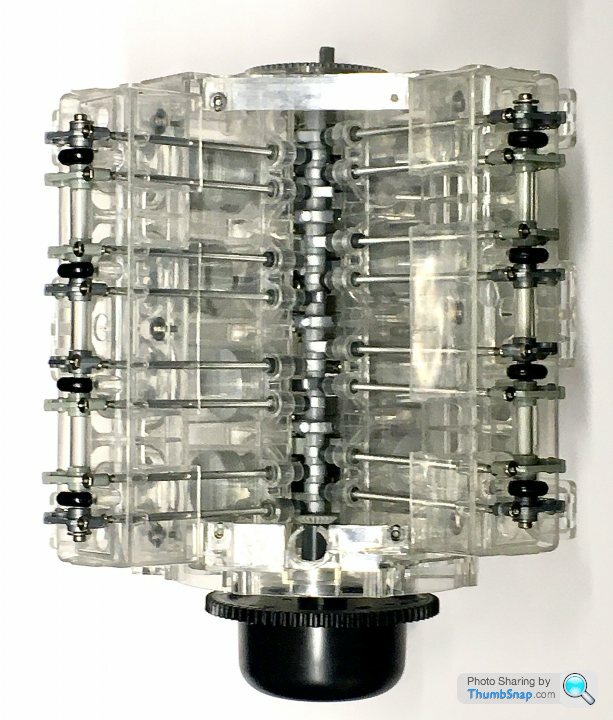
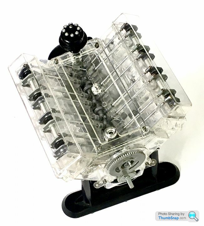
Still a long way to go.
Anyway, it needs finishing, so:
Made some clear plastic inserts for the cam followers. These are a better fit on the newly turned followers, and more importantly, give a longer sliding contact area. This reduces the jamming effect of the originals. I machined them to a top-hat section, and they’re PVA’d in place:
I’d wanted to use tappet adjusters on the rockers, like on a real pushrod engine, but the alignmemts were too far off. I still needed some way of taking up the rattly free play in the system though, so opted to drill the aluminium pushrods and install domed head screws:
These allow everything to be closed up after assembly.
I used some knitting needles off EBay for the rocker shafts. They’re anodised and give a nice smooth action for the rockers without lubrication. The ends were drilled and tapped for retaining screws and washers:
Also visible are the dummy tappet adjusters and lock-nuts. I was reluctant to add these, but the rockers assembly is the most visible part of the model when operating, and it needed a bit more visual interest.
I also found the two original cylinder head retaining screws per side weren’t enough. The heads would tilt under the action of the valves. I added three more by drilling the heads to the inside of the V:
Like all other simulated bolt heads, I replaced the sump fasteners with real screws, and made a brass sump plug:
The weakest point of the model is the distributor bevel gear drive. I’m still refining this, using improved location for the gears, and using a lightly sprung-loaded meshing method. It works, but I’m unsure how long it will keep the correct timing. More of that some other time.
Current progress:
Still a long way to go.
If you're still looking for a geared motor, Proops do this 6 volt, 22rpm one for a fiver.
Proops 6 Volt, 22 rpm motor
As someone mentioned earlier, MFA Como Drills Ltd do a build your own gearbox with a variety of ratios:
MFA Como Drills multi ratio gearbox
Proops 6 Volt, 22 rpm motor
As someone mentioned earlier, MFA Como Drills Ltd do a build your own gearbox with a variety of ratios:
MFA Como Drills multi ratio gearbox
GliderRider said:
If you're still looking for a geared motor, Proops do this 6 volt, 22rpm one for a fiver.
Proops 6 Volt, 22 rpm motor
As someone mentioned earlier, MFA Como Drills Ltd do a build your own gearbox with a variety of ratios:
MFA Como Drills multi ratio gearbox
Yes, still need a motor. 22rpm is a bit slow. Current thinking is to go from 0-60rpm.Proops 6 Volt, 22 rpm motor
As someone mentioned earlier, MFA Como Drills Ltd do a build your own gearbox with a variety of ratios:
MFA Como Drills multi ratio gearbox
I think the MFA gearbox might be a bit bulky and noisy. I really want to fit it in the gearbox, and drive the crankshaft with a co-axial coupling.
Thanks.
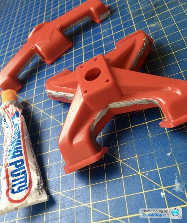
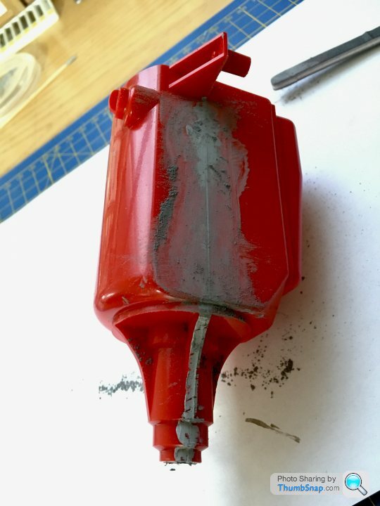
Also filled the huge gaps in the transmission housing:
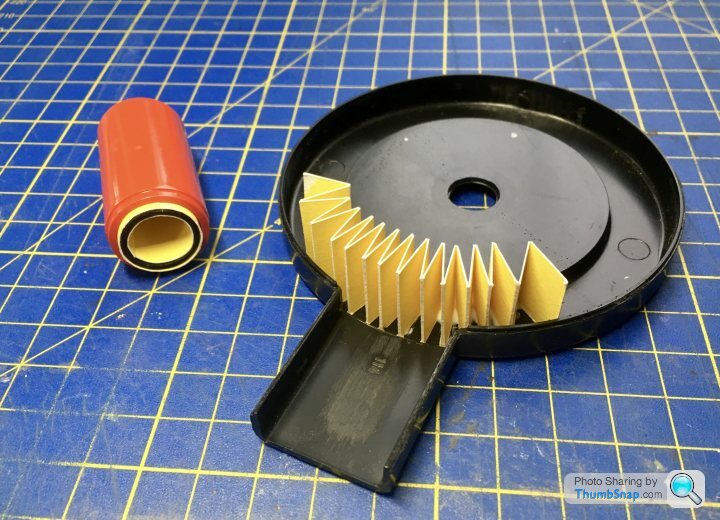
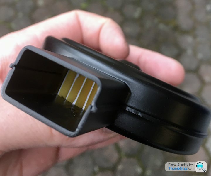
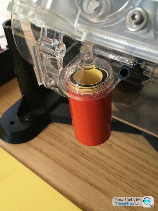
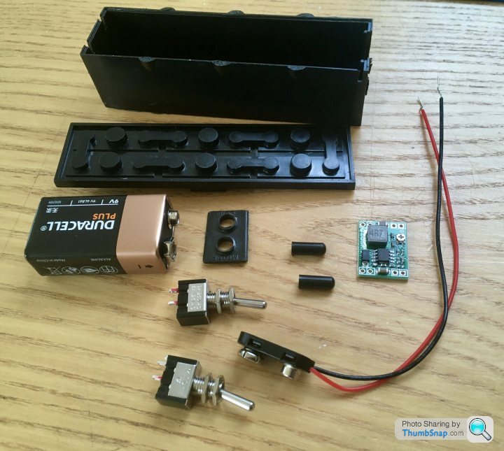
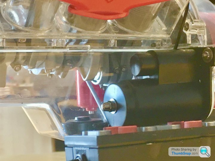
And started gathering parts for the battery box. I found a geared micro 12v motor, which I’m going to run at 9v. I ditched the idea of direct drive, and have instead made a step-down adapter for the original pinion. Also got a voltage reducer so I can use the 9v battery at 3v to power the spark plug lights. The original kit used two plastic push-buttons for the starter and ignition. I’ve got some single pole toggle switches which fit into the original button holes. I’ll drill out the buttons and glue them onto the switch stalks to keep it looking authentic:
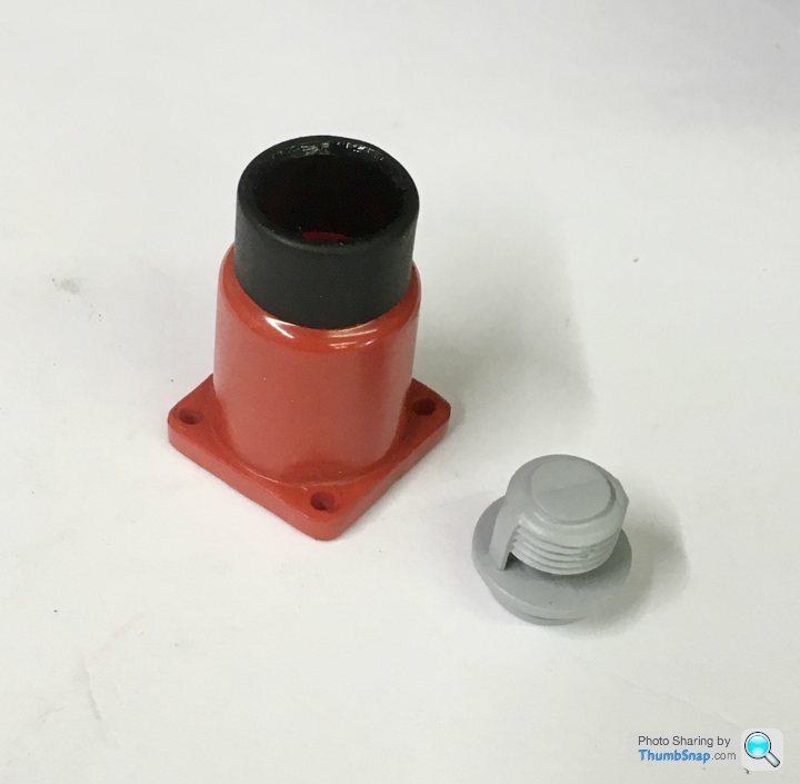
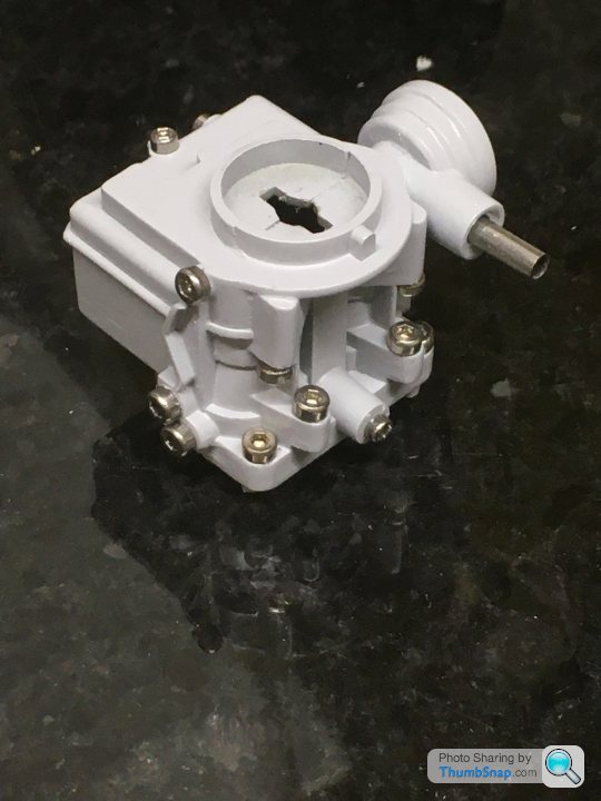
The later version of the starter motor housing is just about the right size to fit over the motor:
And started gathering parts for the battery box. I found a geared micro 12v motor, which I’m going to run at 9v. I ditched the idea of direct drive, and have instead made a step-down adapter for the original pinion. Also got a voltage reducer so I can use the 9v battery at 3v to power the spark plug lights. The original kit used two plastic push-buttons for the starter and ignition. I’ve got some single pole toggle switches which fit into the original button holes. I’ll drill out the buttons and glue them onto the switch stalks to keep it looking authentic:
The later version of the starter motor housing is just about the right size to fit over the motor:
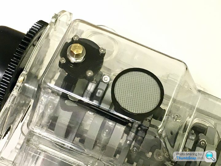
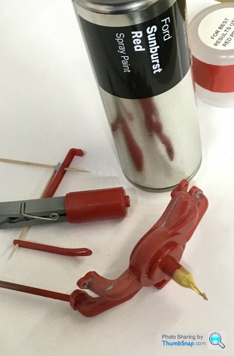
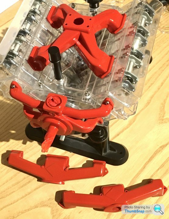
The original carburettor was a bit of a lump:
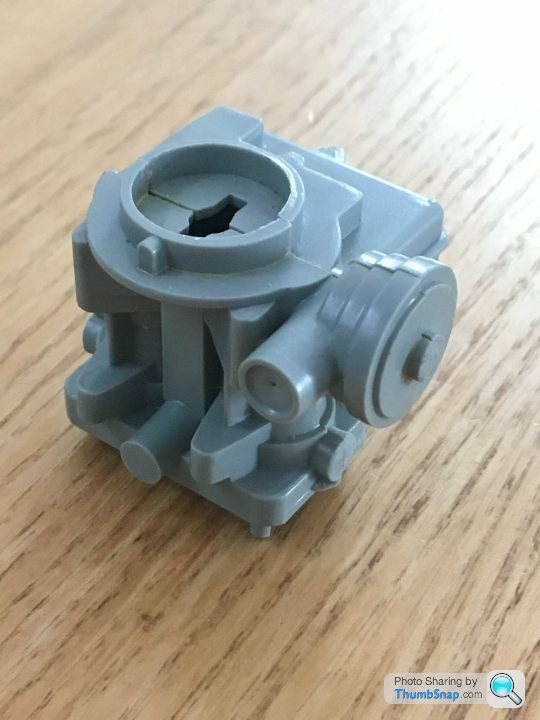
So I added a few fasteners, and an inlet pipe. All probably incorrect, but at least it looks a bit more carburettor like now:
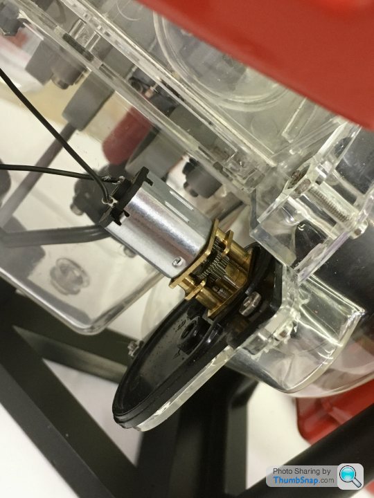
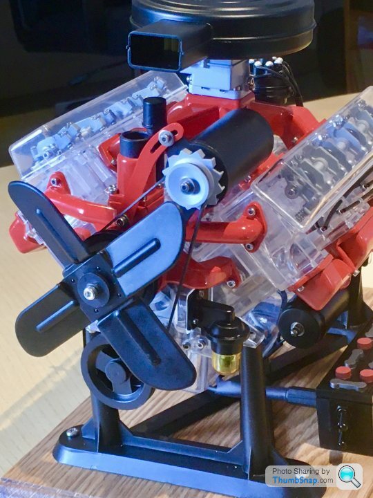
I’ve had to modify the distributor drive a bit, basically adding a light spring to press the bevel gear into the cam gear to make sure it doesn’t skip teeth:
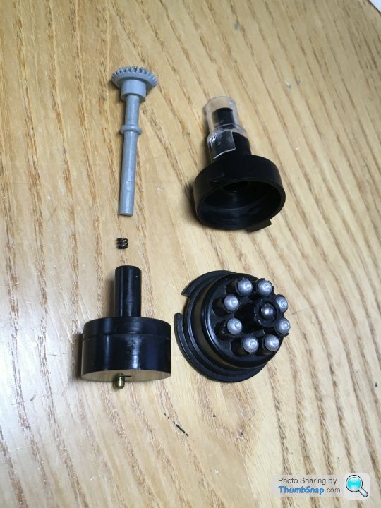
Definitely the weak point of the whole model is the distributor drive. I think it would have been worth Revell fixing it rather than deleting it - the way the distributor works and fires the plugs is really cool.
So I added a few fasteners, and an inlet pipe. All probably incorrect, but at least it looks a bit more carburettor like now:
I’ve had to modify the distributor drive a bit, basically adding a light spring to press the bevel gear into the cam gear to make sure it doesn’t skip teeth:
Definitely the weak point of the whole model is the distributor drive. I think it would have been worth Revell fixing it rather than deleting it - the way the distributor works and fires the plugs is really cool.
Masked up the battery top and painted it to look more like a real battery:

Then final assembly. Of course the first switch-on revealed a blown bulb. Couldn’t believe it, especially since everything worked fine during soldering up, and everything’s now heat-shrunk together. I doubt those incandescent bulbs are available now. Anyway, it’s as done as it’s going to get for now:
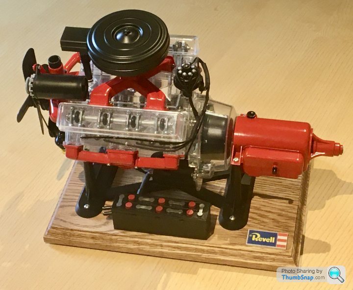
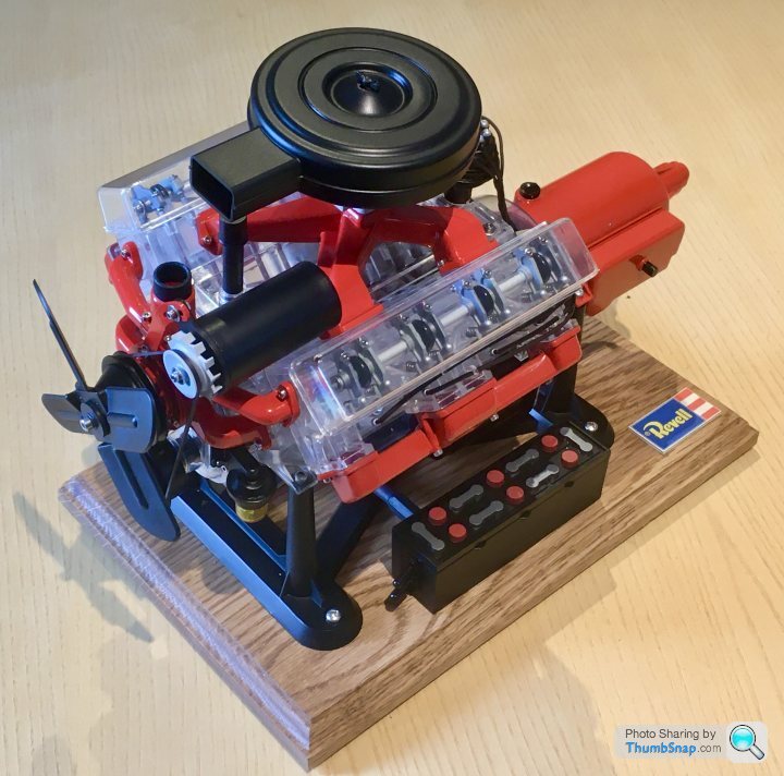
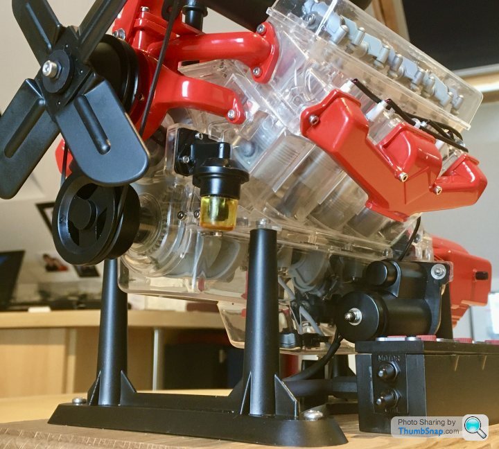
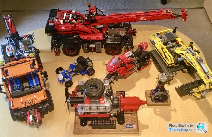
Now takes its place among the other toys in the office…
I’ll post a link to it running once the bulb is repaired.
Then final assembly. Of course the first switch-on revealed a blown bulb. Couldn’t believe it, especially since everything worked fine during soldering up, and everything’s now heat-shrunk together. I doubt those incandescent bulbs are available now. Anyway, it’s as done as it’s going to get for now:
Now takes its place among the other toys in the office…
I’ll post a link to it running once the bulb is repaired.
Gassing Station | Scale Models | Top of Page | What's New | My Stuff