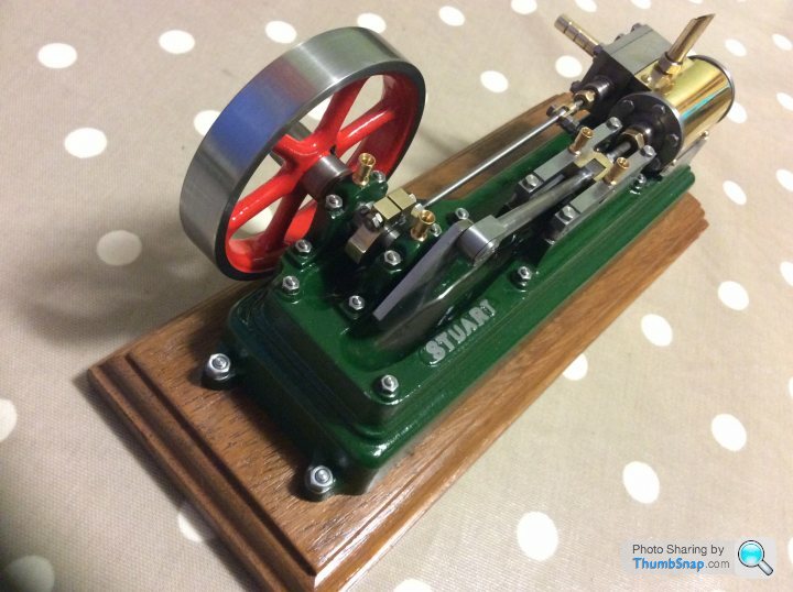
Stuart 10V Vertical Steam Engine
Discussion


Tango13 said:
dr_gn said:
I don’t have to *hope* it’s in the centre at all, because it’s irrelevant: Lock the x-axis, touch on the curved surface, zero, lift and move to the opposite side in the y axis, lower and touch the other side. Divide the Y DRO reading by two and that’s precisely the y-axis centreline irrespective of if it’s on the tangent point or not. The y-axis is locked - it’s in the exact same position on the curve, but on the opposite side. Repeat in x, and there’s the exact centre, should I need it.
Takes far longer to describe than to do.
The moving vice jaw doesn’t necessarily move perfectly parallel to the fixed one when clamping a Non-parallel part, so I’d potentially be measuring a non-symmetrical taper and therefore getting a false centre.
Why on earth would I spend all that money on an elaborate tool when I can do the same thing perfectly well with what I’ve already got?
In 30+ years of precision engineering I have never seen anyone try to set a datum on a round part like that because if they did they would get laughed out of the factory!Takes far longer to describe than to do.
The moving vice jaw doesn’t necessarily move perfectly parallel to the fixed one when clamping a Non-parallel part, so I’d potentially be measuring a non-symmetrical taper and therefore getting a false centre.
Why on earth would I spend all that money on an elaborate tool when I can do the same thing perfectly well with what I’ve already got?
A moving jaw is irrelevant for setting a datum, set the datum off the fixed jaw and work back from that if you want to do it the hard way or just buy the correct tool for the job which will be quicker, easier and more accurate.
Why would I buy a device that may or may not be more accurate than what I’ve already got, when the parts I’m making are to completely un-toleranced drawings?
I somehow doubt that it would be quicker, since it only takes me about one minute to do currently. Even if it took a hour, so what? I’m not building this in a factory, and model engineering in a garage is very different from production engineering.
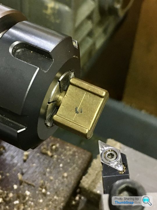
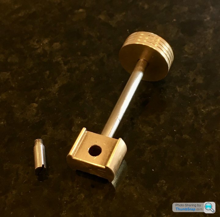
On to the cross head, which is supplied as a brass stamping. It’s got a spigot, which is handy for holding it for initial work. First job was to face the end:
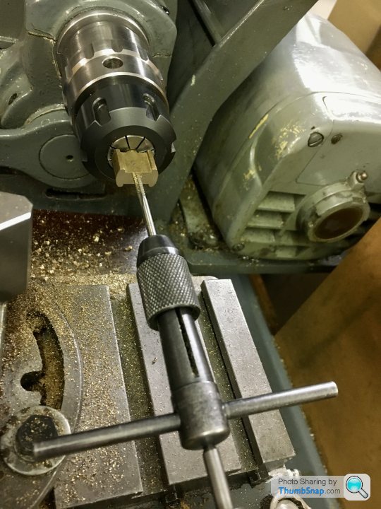
Drill and tap for the piston rod:
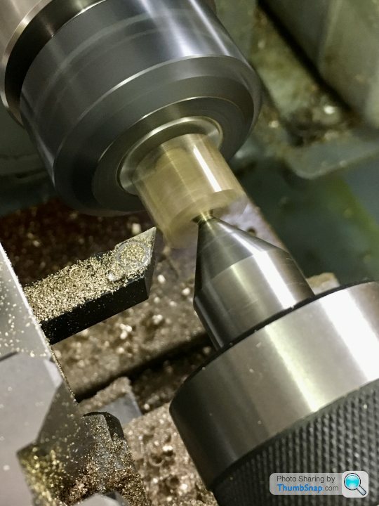
Then turn the O/D to within about 0.010” of finished:
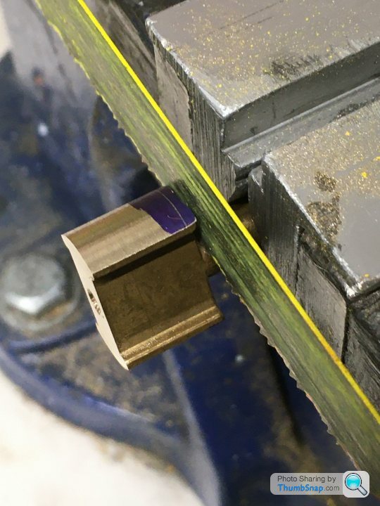
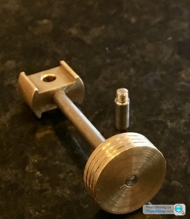
Saw off the spigot:
Tighten onto the piston rod, mark it so it can be tightened to the same position in future. Then mount in the collet chuck and incrementally turn to size for the standard bore. A good tip to easily get fractions of a thou feed is to turn the compound slide to a slight angle to the bed, such that any turn on the crank translates to a much smaller amount of feed into the work:
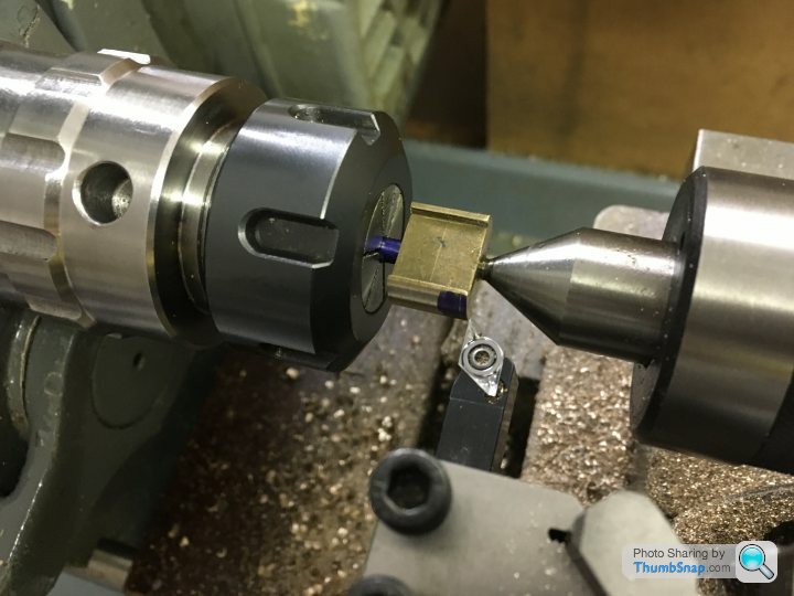
The final feature is the connecting rod hole. I was concerned that due to any errors in size accumulating from my own work, combined with the un-toleranced drawings, I might end up with the piston crashing into the cylinder caps. I decided to temporarily assemble the cylinder, measure it’s internal bore length, and calculate the clearances at each end based on the actual crank throw.
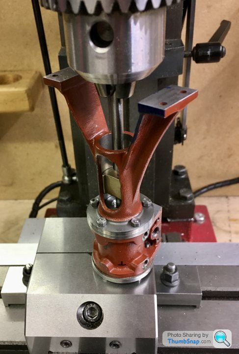
Measured the throw by using the z-dro on the mill:
...and the bore length by measuring the piston displacement in a similar way:
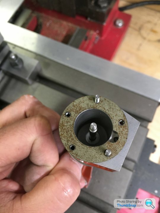
From these figures I calculated that I needed 0.7mm clearance at each end of the bore. I made a 0.7mm thick washer and put it in the bottom of the cylinder:
Then, with the crank at the bottom of its stroke, marked the hole position:
Double-checked at the top of the stroke, spot-on:
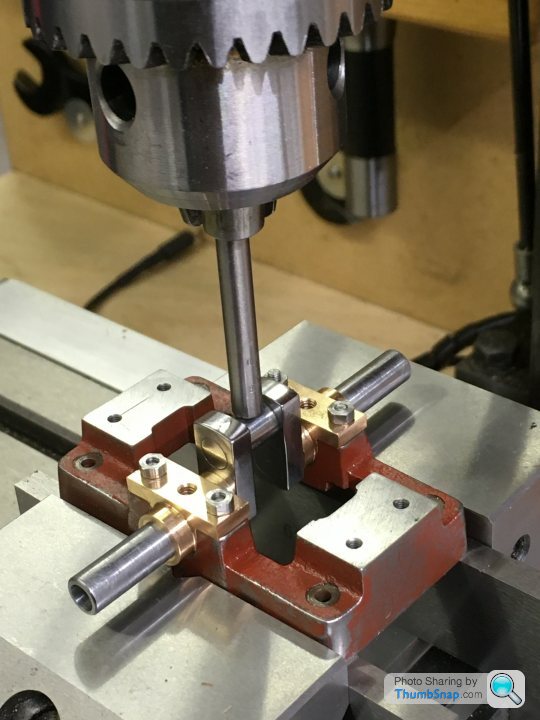
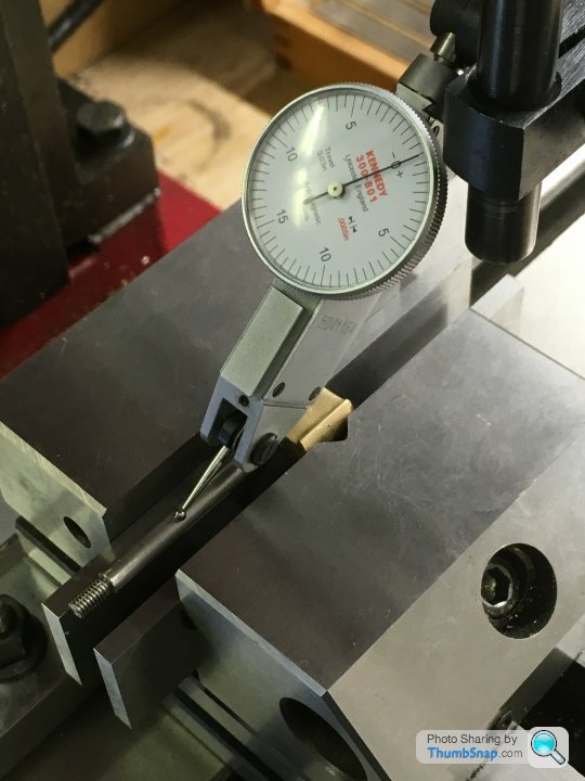
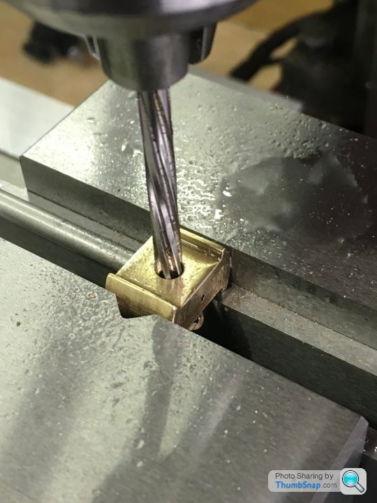
So then dis-assembled, and mounted in the mill vice. Double-checked it was level, then marked, drilled and reamed the pin hole:
Next up is making the threaded pin. I think that’s the last bit of machining before test assembly.
Don’t want to speak too soon, but I expected this build to take me at least a year rather than 5 months!
Drill and tap for the piston rod:
Then turn the O/D to within about 0.010” of finished:
Saw off the spigot:
Tighten onto the piston rod, mark it so it can be tightened to the same position in future. Then mount in the collet chuck and incrementally turn to size for the standard bore. A good tip to easily get fractions of a thou feed is to turn the compound slide to a slight angle to the bed, such that any turn on the crank translates to a much smaller amount of feed into the work:
The final feature is the connecting rod hole. I was concerned that due to any errors in size accumulating from my own work, combined with the un-toleranced drawings, I might end up with the piston crashing into the cylinder caps. I decided to temporarily assemble the cylinder, measure it’s internal bore length, and calculate the clearances at each end based on the actual crank throw.
Measured the throw by using the z-dro on the mill:
...and the bore length by measuring the piston displacement in a similar way:
From these figures I calculated that I needed 0.7mm clearance at each end of the bore. I made a 0.7mm thick washer and put it in the bottom of the cylinder:
Then, with the crank at the bottom of its stroke, marked the hole position:
Double-checked at the top of the stroke, spot-on:
So then dis-assembled, and mounted in the mill vice. Double-checked it was level, then marked, drilled and reamed the pin hole:
Next up is making the threaded pin. I think that’s the last bit of machining before test assembly.
Don’t want to speak too soon, but I expected this build to take me at least a year rather than 5 months!
For some reason I didn’t have enough rod left in the kit to make the pin - I think I made a mistake with the valve rod and had to scrap it. It was only a 15 minute job to turn one from an off-cut of steel though.
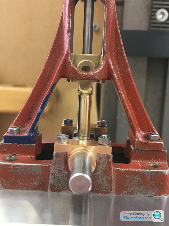
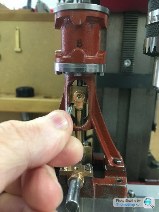
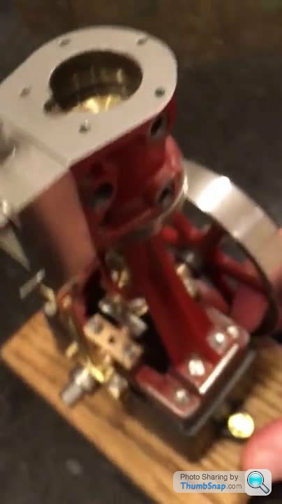
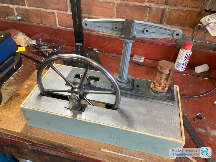
So here’s the first go at test assembly of all the mechanical parts:
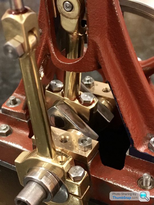
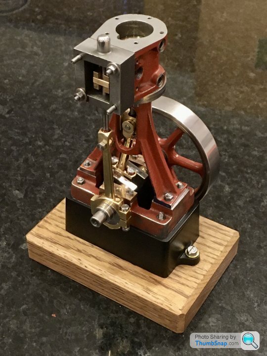
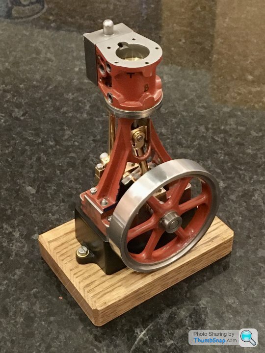
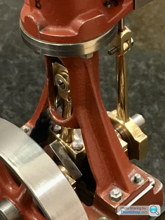
And a video clip of it moving, lubricated with some light oil. Valve and timing setup isn’t done yet, and there is no gland packing. There is one slightly tight spot towards the bottom of piston travel, but it’s getting more free as I fiddle with it:
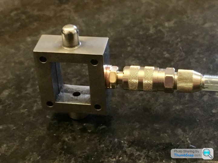
Next job is to make the inlet and exhaust fittings. I’ve got some hexagon bar on order, so they shouldn’t take long to make.
So here’s the first go at test assembly of all the mechanical parts:
And a video clip of it moving, lubricated with some light oil. Valve and timing setup isn’t done yet, and there is no gland packing. There is one slightly tight spot towards the bottom of piston travel, but it’s getting more free as I fiddle with it:
Next job is to make the inlet and exhaust fittings. I’ve got some hexagon bar on order, so they shouldn’t take long to make.

Made a start on painting the castings yesterday. Cleaned down with brake cleaner, and masked with Tamiya tape and Blu-Tack:
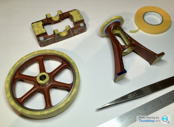
Primed with Tamiya fine surface primer and airbrushed with several thick coats of paint. After all the research I’ve done over the months, I’m fed up with the sight of green 10Vs, so decided on Dark Blue Meccano enamel that my dad bought decades ago, but never used. I think it will look great with polished silver and brass:
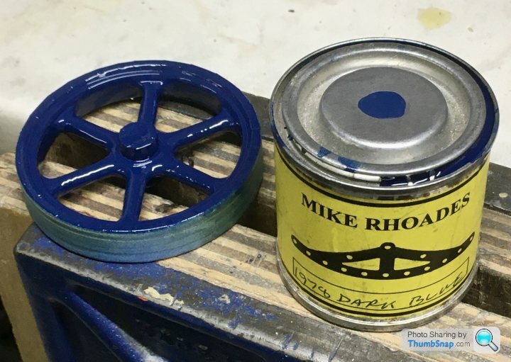
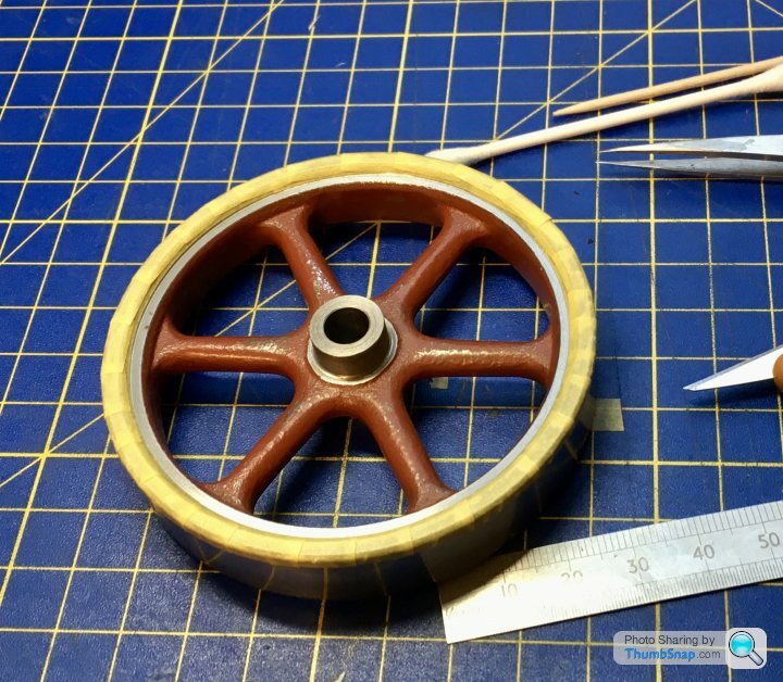
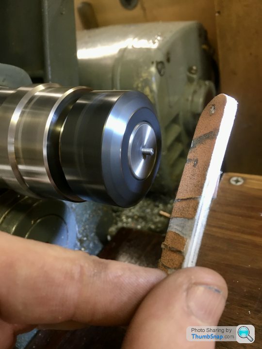
As expected, a few bits peeled off the smooth flywheel areas on removing the tape (should have removed it before the paint flashed off). Not a problem though because I’d always planned on a final corrective coat done in the lathe to get as concentric a demarcation as possible:
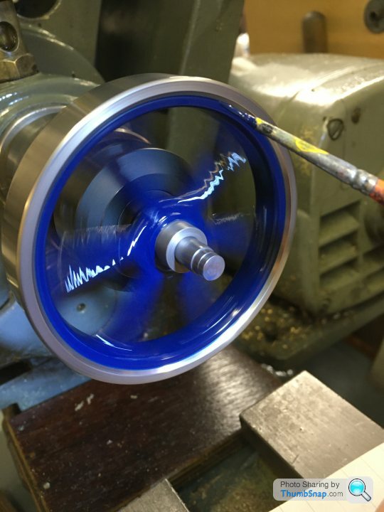
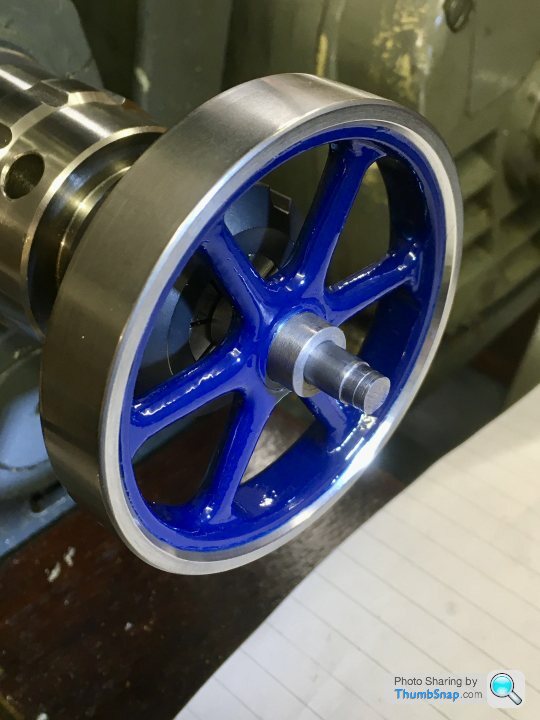
I often use this technique on scale models to get perfectly concentric painted bands on various things.
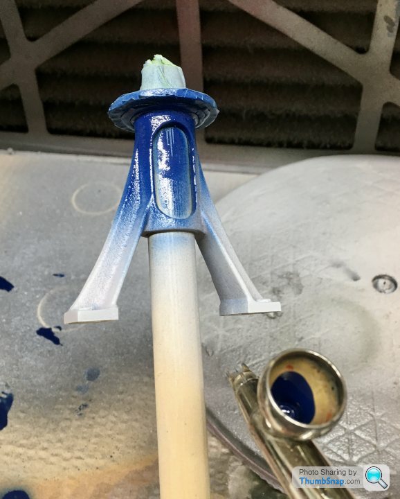
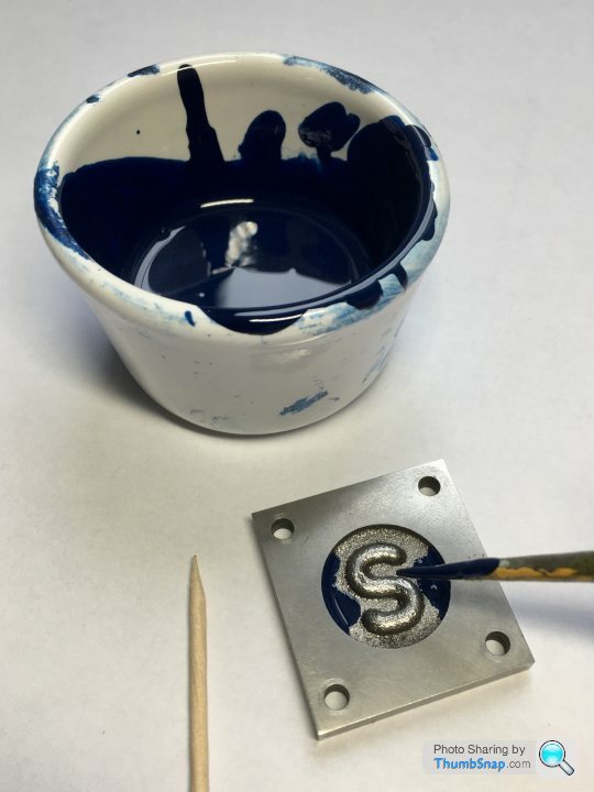
I thinned the paint a bit for the valve cover, and blobbed it into the cast recess, letting capillary action do the work:
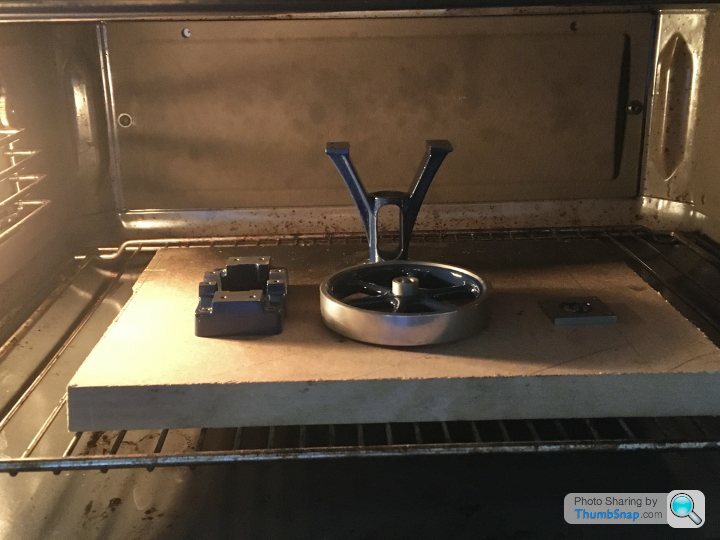
Then into the oven to bake out the solvents and harden the paint a bit:
Pretty much done:
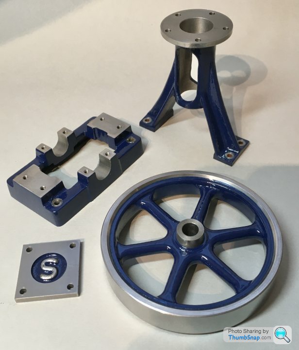
Primed with Tamiya fine surface primer and airbrushed with several thick coats of paint. After all the research I’ve done over the months, I’m fed up with the sight of green 10Vs, so decided on Dark Blue Meccano enamel that my dad bought decades ago, but never used. I think it will look great with polished silver and brass:
As expected, a few bits peeled off the smooth flywheel areas on removing the tape (should have removed it before the paint flashed off). Not a problem though because I’d always planned on a final corrective coat done in the lathe to get as concentric a demarcation as possible:
I often use this technique on scale models to get perfectly concentric painted bands on various things.
I thinned the paint a bit for the valve cover, and blobbed it into the cast recess, letting capillary action do the work:
Then into the oven to bake out the solvents and harden the paint a bit:
Pretty much done:
dhutch said:
Looks amazing, red is also nice, but definitely better than green.
Agreed - it has to be one of those three colours, or maybe black if you’re desperate. I had the dark blue paint sitting in a box so thought why not use it. I also like the Meccano connection somehow. The old 1930’s Meccano dark red would look nice too I think.Still waiting for a small step drill to arrive, to open up the jacket holes, and the hex bar to make the steam fittings.
Halmyre said:
Having followed this thread, I can understand why the unmachined Stuart kit is £96 and the machined kit is £466.
Actually £559.44 with VAT. Then postage on top.For the ready to run model it’s an eye-watering £803.76.
OK, it’s an ancient design, not really designed for commercial manufacture, but still, those prices are...interesting.
Few loose ends to tidy up.
The holes positions for the cylinder cladding screws are such that the undersides are unsupported, making the cladding bow on tightening. I made some Milliput bosses, filed flush, then painted satin black:

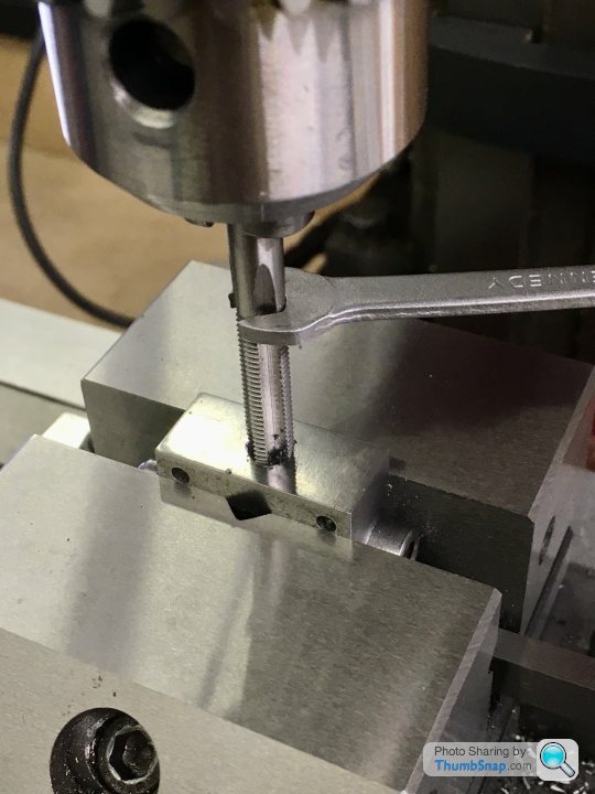
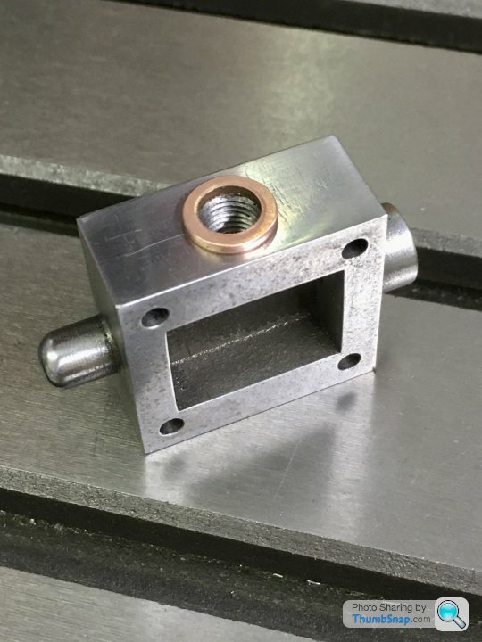
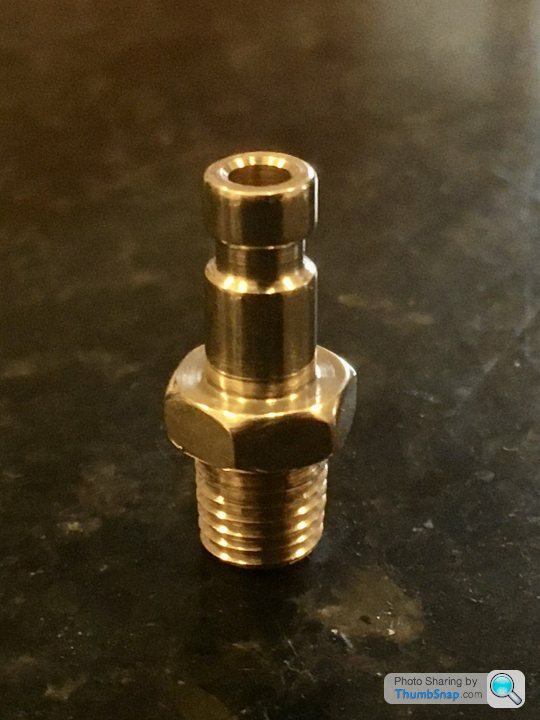
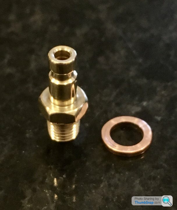
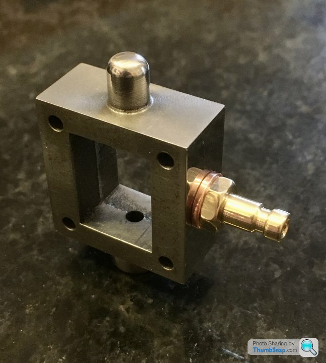
Then the 1/4” thread for the steam inlet union:
And made a sealing washer parted off from some old copper pipe. Needs annealing:
The holes positions for the cylinder cladding screws are such that the undersides are unsupported, making the cladding bow on tightening. I made some Milliput bosses, filed flush, then painted satin black:
Then the 1/4” thread for the steam inlet union:
And made a sealing washer parted off from some old copper pipe. Needs annealing:
Edited by dr_gn on Friday 9th October 18:15
Every time I looked at the connecting rod:
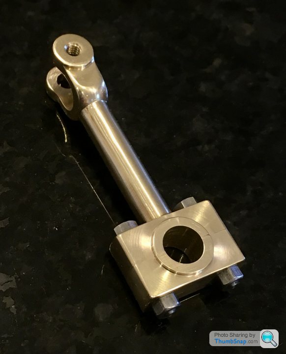
...I saw an Elephant’s leg.
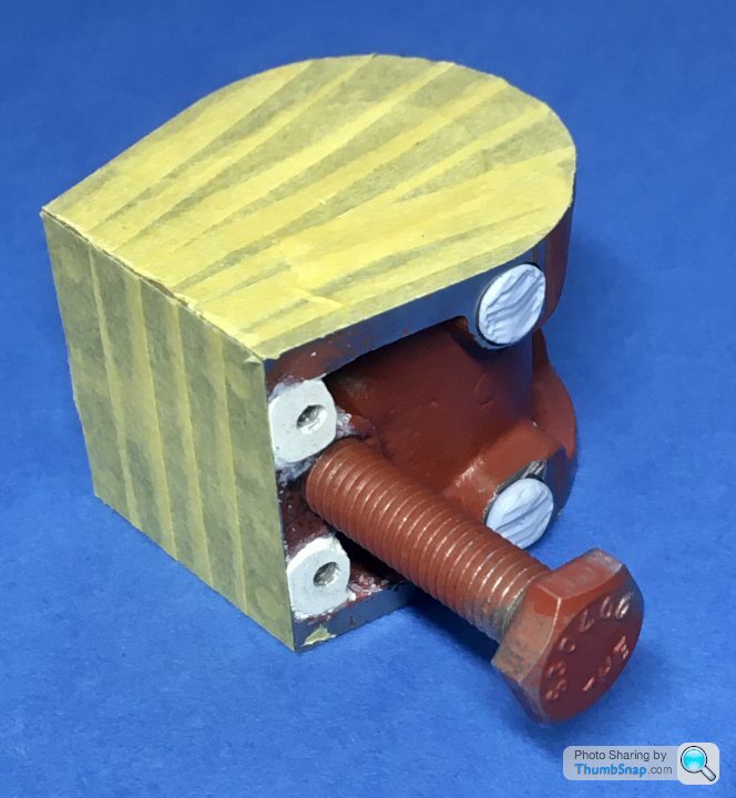
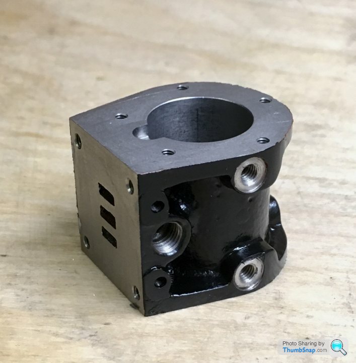
By mistakenly sawing off the turning spigot, I gave myself a problem in how to hold it to subsequently taper-turn the shaft. The main bearing block is turned to a diameter, so I decided to try and make a split fixture for that end, and clamp an aluminium block in the little end for centre drilling:
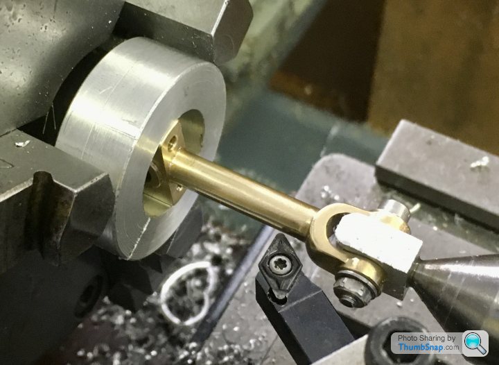
I drew it out on CAD, and settled on a 3 degree included angle taper. After setting the compound slide to 1 1/2 degrees, try as I might, I couldn’t get any of my turning tools to do it in one pass. I ended up doing half, then re-setting the tool and doing the rest. After a quick polish you can’t see the join. It now looks better:
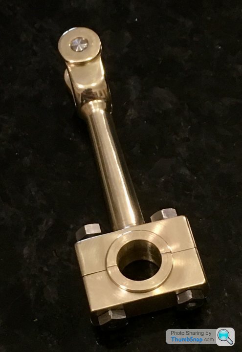
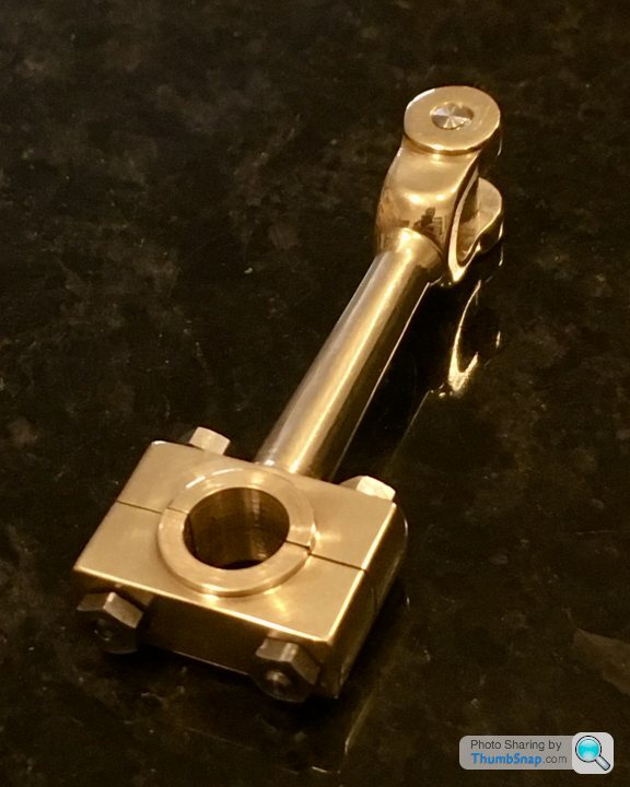
Also cleaned up all the Little end pin end, the stud ends and bolt heads - most of them had prominent pips:
So now I’m waiting for some supplies to make the unions and open up the cladding holes, and it’ll be on to assembly and testing.
It’s worth noting that as I went through all the supplied fasteners, I found two of the nuts were half-nuts - probably for the eccentric clamp bolt. I’d already made my own half nuts by turning down some standard ones. I’ll just use the supplied ones for the big-end caps instead.
...I saw an Elephant’s leg.
By mistakenly sawing off the turning spigot, I gave myself a problem in how to hold it to subsequently taper-turn the shaft. The main bearing block is turned to a diameter, so I decided to try and make a split fixture for that end, and clamp an aluminium block in the little end for centre drilling:
I drew it out on CAD, and settled on a 3 degree included angle taper. After setting the compound slide to 1 1/2 degrees, try as I might, I couldn’t get any of my turning tools to do it in one pass. I ended up doing half, then re-setting the tool and doing the rest. After a quick polish you can’t see the join. It now looks better:
Also cleaned up all the Little end pin end, the stud ends and bolt heads - most of them had prominent pips:
So now I’m waiting for some supplies to make the unions and open up the cladding holes, and it’ll be on to assembly and testing.
It’s worth noting that as I went through all the supplied fasteners, I found two of the nuts were half-nuts - probably for the eccentric clamp bolt. I’d already made my own half nuts by turning down some standard ones. I’ll just use the supplied ones for the big-end caps instead.
fourfoldroot said:
dr_gn said:
fourfoldroot said:
I’ve been looking at the Stuart models website to look for a next model; that looks like an S50, not a 10H.My second project was the S50 above,but was not really any harder than the 10V, possibly a bit easier.
I’m currently tackling a Sanderson beam engine. I can’t say I’m loving the castings. They are very poorly cast compared to Stuart and some of them are undersized. They are a very old set from ebay. I’m guessing the current offerings are much better.
After asking the question on the ME forum "What's a good second model", I'm going with my desire to build a Stuart Twin Victoria. However, after getting some wisdom from the guys over there, I wont be spending £625 of the full kit, but only buying the drawings, and the main castings, which should come to less than £200. I'll be sourcing all the raw materials supplied in the kit from my local metals company, and all the ME fasteners online. The box beds are castings, but it's been suggested that these can easily be made from aluminium bar and JB weld, and will be indistinguishable form castings once shot blasted, painted and machined. The governor kit for it looks nice, so I'll get that too. So - a much more complex build, slightly different valve gear; a step on from the 10V, and a few new techniques too.
I also mentioned my ambition to one day build a traction engine. To my surprise everyone who commented urged me to start on this long-term project now. It's a bit daunting, but I'll be starting on the "Minnie" 1" scale traction engine next year. It's a model that was first outlined in Model Engineer magazine in 1969/70. I am currently compiling all the relevant issues. It's a popular design, and many of the parts such as wheel parts, gears and main castings are commercially available. The most expensive individual component will be the certified boiler, which I will order from a specialist. Apparently it's about a 1 year waiting list, so by that time so other parts should be done.
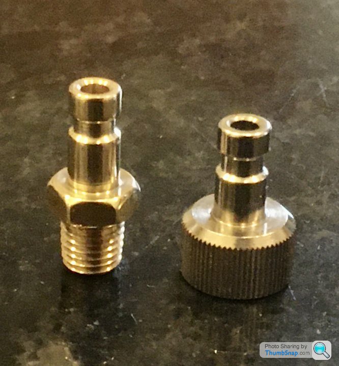
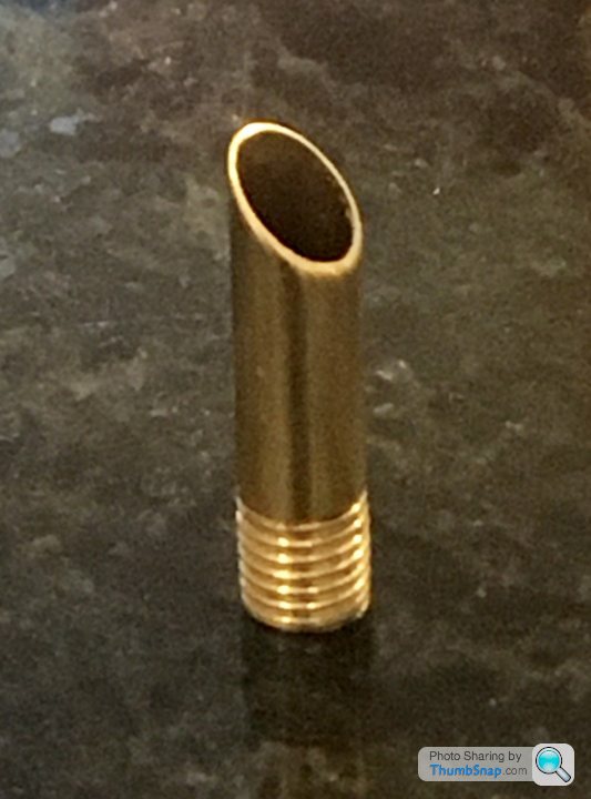
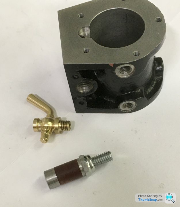
Made a simple exhaust stub by threading some brass tube:
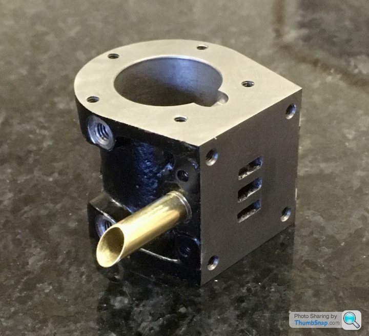
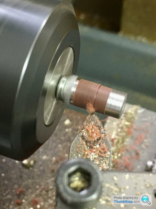
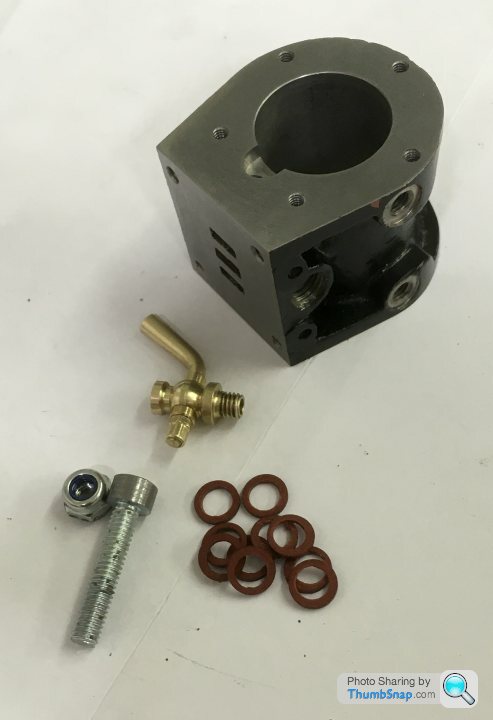
Also turned down some fibre washers so they fit on the drain cock spot-faces. I can adjust the washer thicknesses until the orientation of the drains is right when tight:
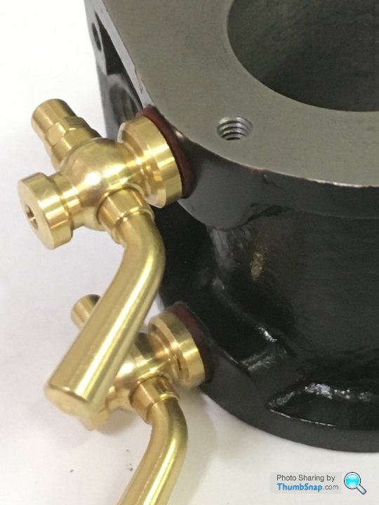
Still waiting for a step drill for the cladding, then that’ll be it.
Also turned down some fibre washers so they fit on the drain cock spot-faces. I can adjust the washer thicknesses until the orientation of the drains is right when tight:
Still waiting for a step drill for the cladding, then that’ll be it.
fourfoldroot said:
Start on both. The victoria will give you something to achieve a finished model and build up skills for machining the more complex parts of the Minnie. It will extend the period to build up castings from abandoned projects on ebay.
I was gifted an entire workshop, machines and materials by a lady after her husband died. He was the model engineer. She was a domestic science teacher. Feeling the need to join in she built a 2” Fowler B1 ploughing engine including boiler as her first project. It is one of the finest large models I have ever seen. She then assisted her husband with his projects and for herself built wooden boat kits.
Wow. That's some wife!I was gifted an entire workshop, machines and materials by a lady after her husband died. He was the model engineer. She was a domestic science teacher. Feeling the need to join in she built a 2” Fowler B1 ploughing engine including boiler as her first project. It is one of the finest large models I have ever seen. She then assisted her husband with his projects and for herself built wooden boat kits.
Yes - I've fallen into the "huge model" trap with the paper/card Bismarck. Previously I'd built 4 ships in 4 years, and had the satisfaction of completing them, but the Bismark is languishing on its shelf not even 1/10 complete after 14 months...
I’ve got a Wilesco valve that I might try to use on the 10V somehow:
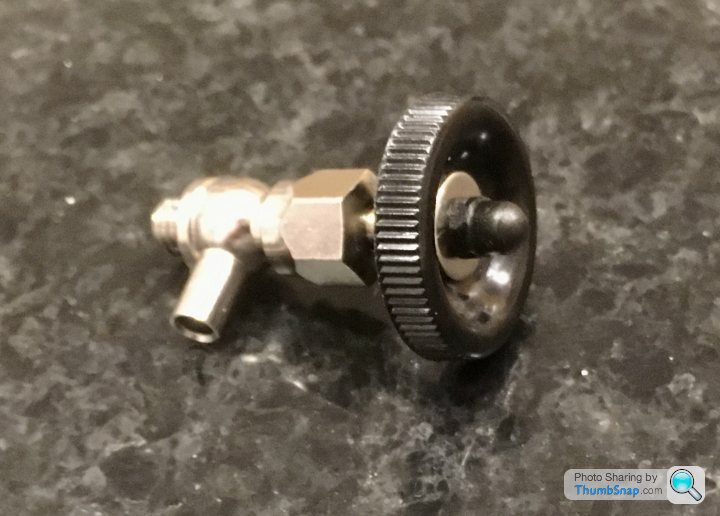
I suppose I’m scratching about looking for things to make until the step drill arrives and I can call it done, but anyway. The black plastic wheel looked a bit cheap, so I made a replacement out of scrap brass:
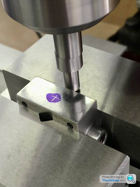
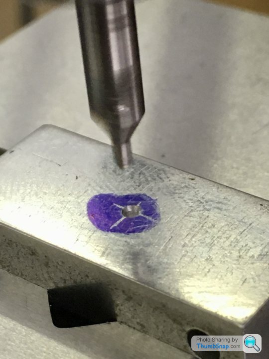
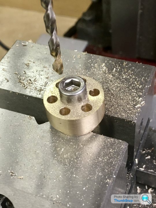
Bolted it to some brass hexagon bar and put in the vice, then got the centre using the edge finder:
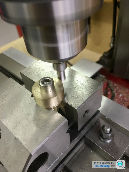
Then co-ordinate drilled the holes in the correct orientation for milling the edge detents using the hexagon bar as a 60 degree angle fixture:
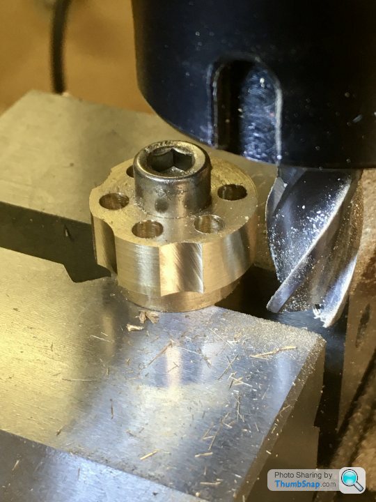
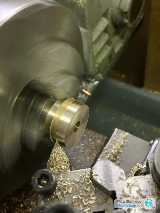
Then back in the lathe for parting off and profiling the faces:
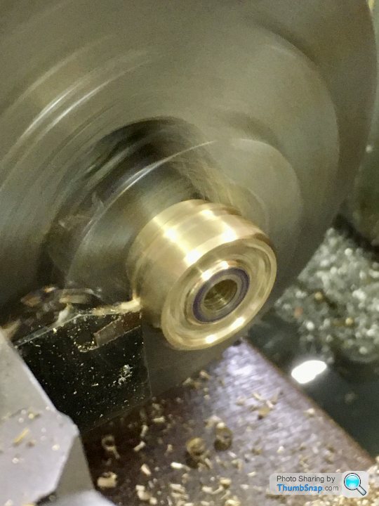
Used a square file to open up the central hole to suit the original slotted plate. I’d used a 4mm drill so the circumference quadrant points could be used a filing limit for the square edges:
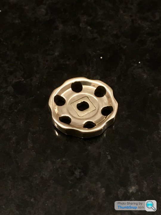
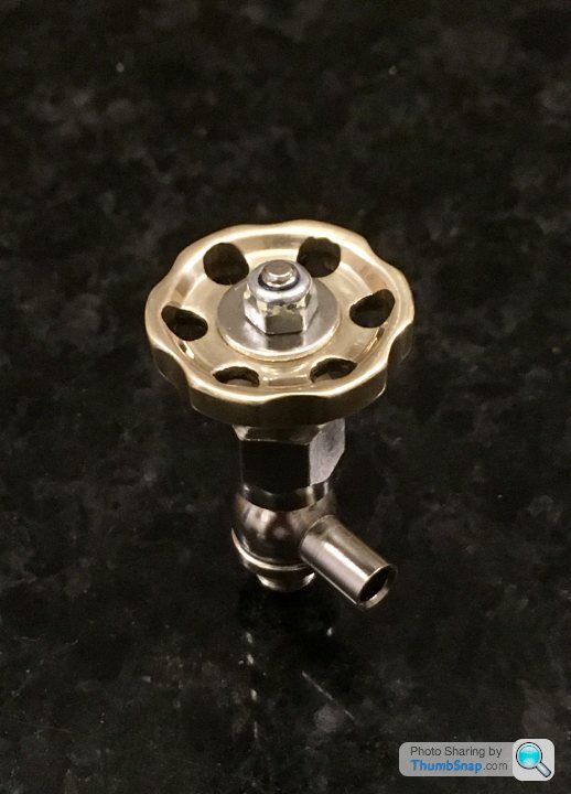
I suppose I’m scratching about looking for things to make until the step drill arrives and I can call it done, but anyway. The black plastic wheel looked a bit cheap, so I made a replacement out of scrap brass:
Bolted it to some brass hexagon bar and put in the vice, then got the centre using the edge finder:
Then co-ordinate drilled the holes in the correct orientation for milling the edge detents using the hexagon bar as a 60 degree angle fixture:
Then back in the lathe for parting off and profiling the faces:
Used a square file to open up the central hole to suit the original slotted plate. I’d used a 4mm drill so the circumference quadrant points could be used a filing limit for the square edges:
dhutch said:
I would love the build a traction engine, but would pick a larger scale. Either 4" or maybe 6" and then you could plod round the rally field on it!
Daniel
I hear what you’re saying, but for me at some point practicality has to prevail: Cost, weight and timescales are against me for a large model. The 1” was also designed specifically such that the largest turned parts (rear wheels) could be done on a small lathe like the ML7, so there is some reasoning behind the scale. Daniel
I’ve got a Wilesco Steam roller that I’m supposed to be making a bit more realistic with various parts. I’ll probably get that done before starting on the ‘proper’ one. All good fun.
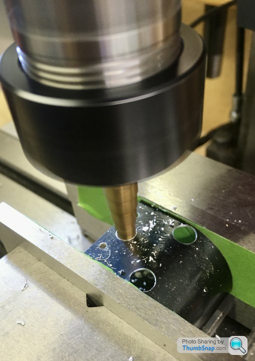
Step drills arrived today:
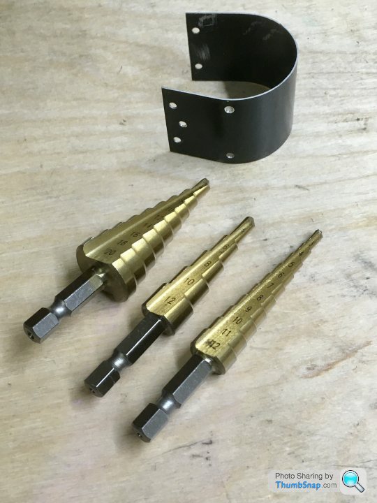
I used some parallels to extend the jaws upwards, and put masking tape on the surfaces to give some extra grip, then re-aligned the pilot holes:
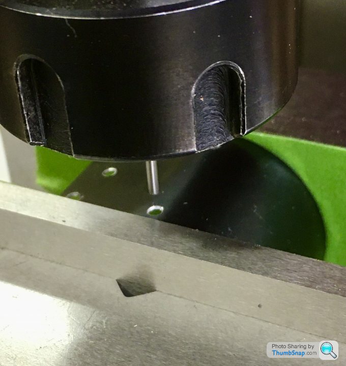
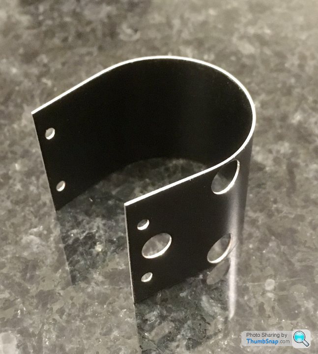
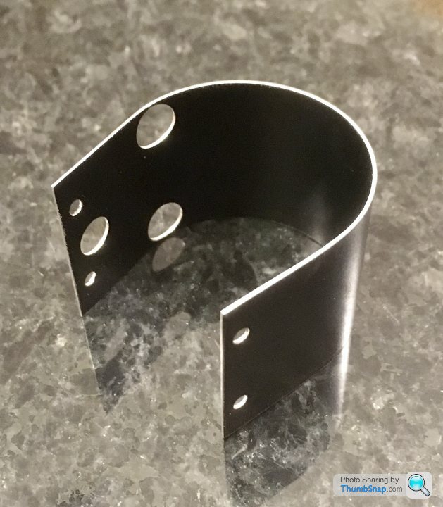
The drain cock holes were less than 1mm from the edge, but the drills worked really well:
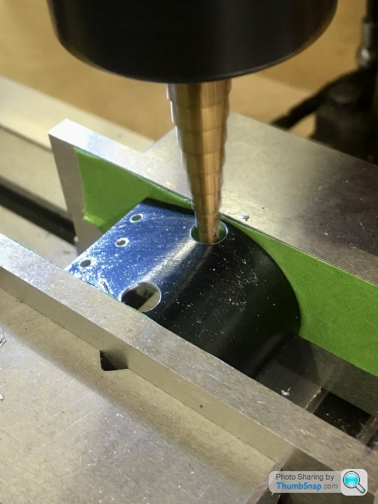
Exhaust hole wasn’t a problem:
I ended up spraying it satin black, then cleaned up the edges with wet & dry:
So final assembly and testing next.
I used some parallels to extend the jaws upwards, and put masking tape on the surfaces to give some extra grip, then re-aligned the pilot holes:
The drain cock holes were less than 1mm from the edge, but the drills worked really well:
Exhaust hole wasn’t a problem:
I ended up spraying it satin black, then cleaned up the edges with wet & dry:
So final assembly and testing next.
Gassing Station | Scale Models | Top of Page | What's New | My Stuff