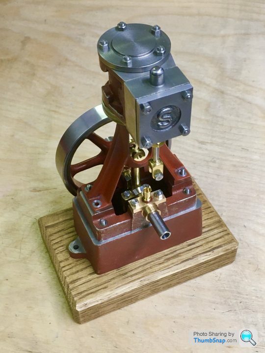
Stuart 10V Vertical Steam Engine
Discussion


rolster said:
As always the builders choice is what matters, not us interlopers. I look forward to seeing how you progress on this build.
I appreciate the suggestions, and I actually think a lobed crankshaft would look better than the standard version. For a first model though, I'm conscious that by reprofiling the webs, I'd be compensating for an error. I'd rather try to get it right as per the plans this time. I 'phoned a metal procurement company just up the road and they have half a metre of 3/8" x 3/16" bright mild steel strip for £1. So for that, I'll try again.
So...crank webs part deux. The spare material from Stuart Models is £10.46 (delivered) for a 2” length. My local materials company supplied my 1/2 metre for £1.20. I’ll not comment further on that,
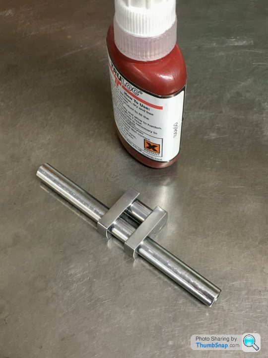
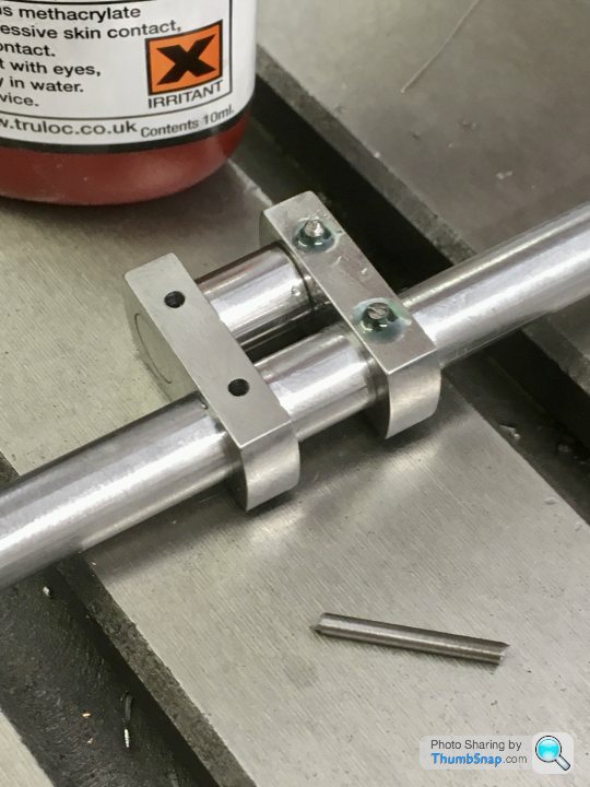
First job - Loctite two pieces together:
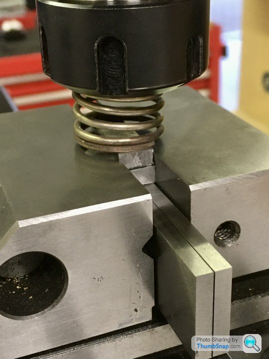
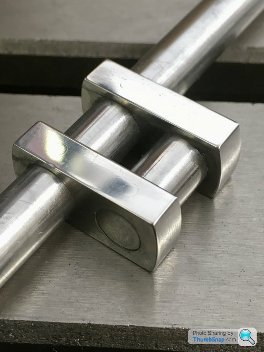
Then fly-cut the edges to clean them up a fraction to be perfectly flat and parallel:
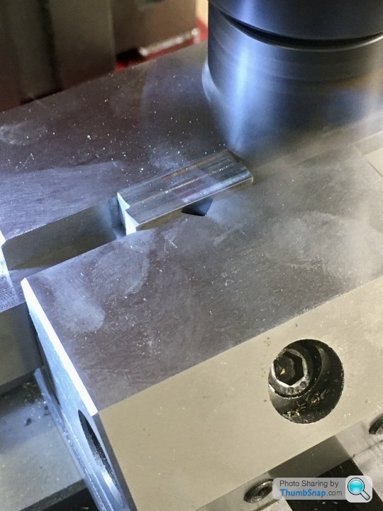
Mill the ends to be square:
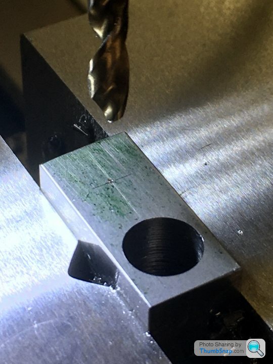
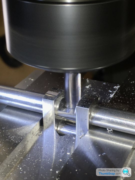
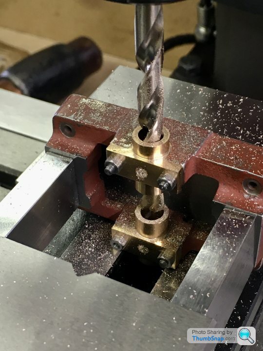
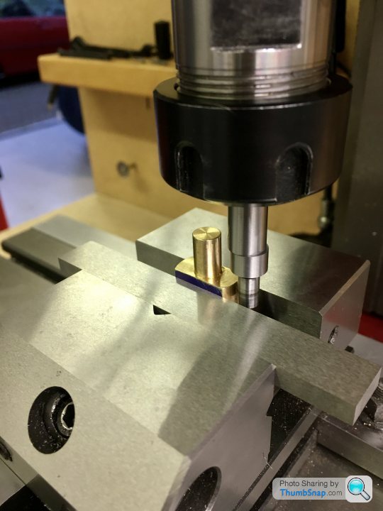
Mark out, then put in the vice and check for level:
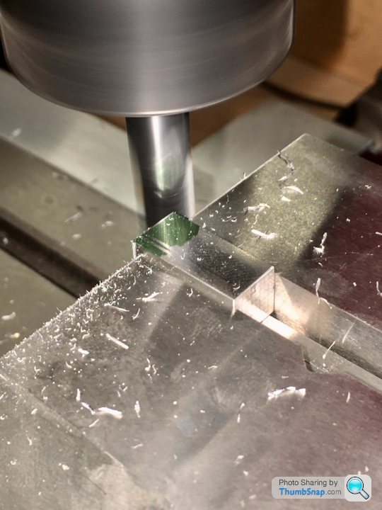
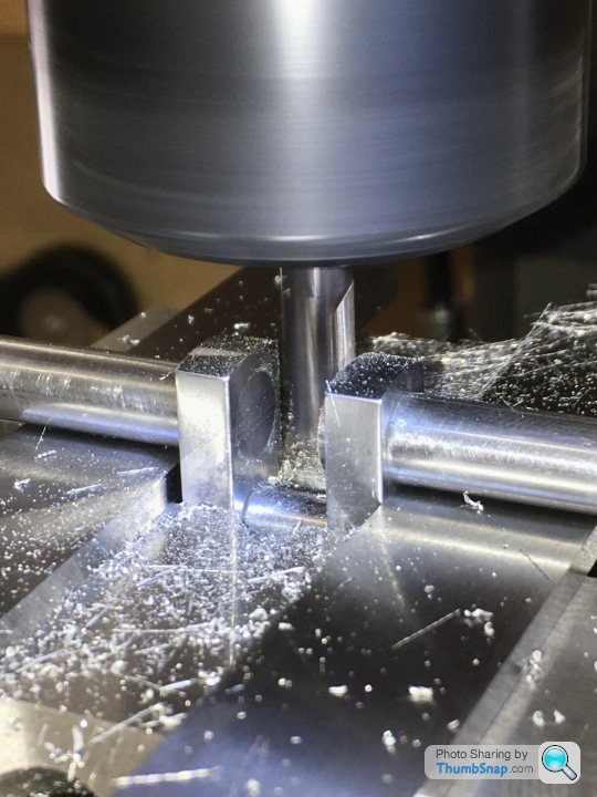
Co-ordinate drill/ream the holes, having first used the edge finder to get the datums. This time I used the marking out as a double-check:
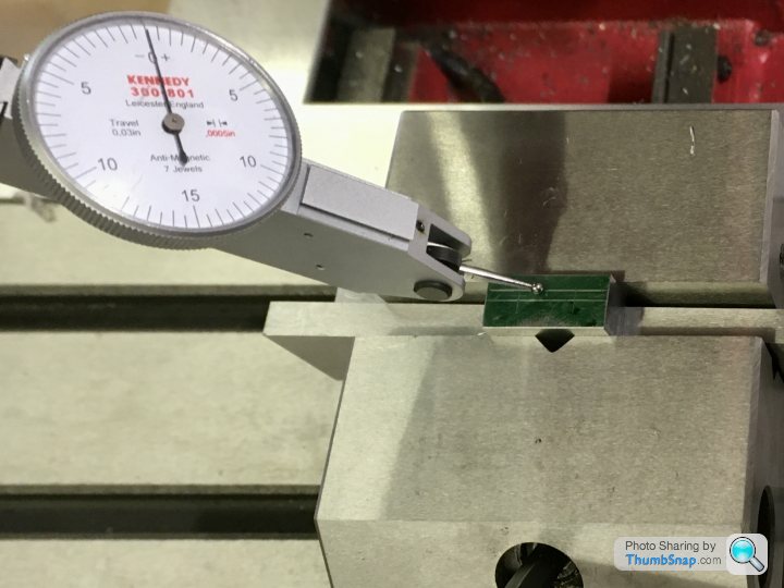
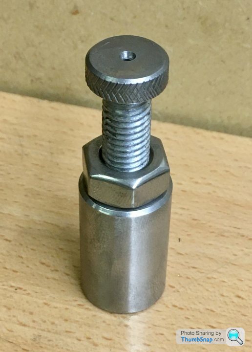
Then used the nut and bolt method to turn the end radii:
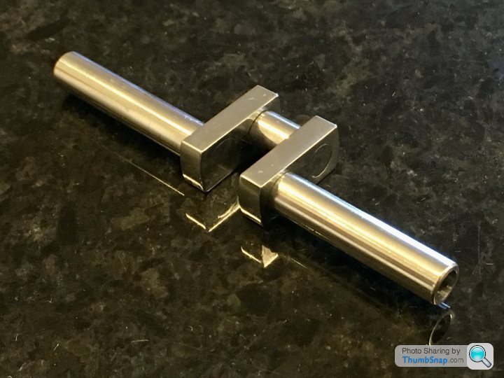
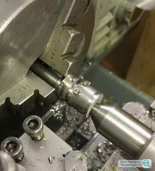
Then machined the main shaft. Not sure why there’s a hole in one end, but it’s on the drawing:

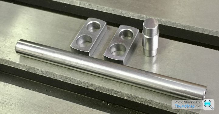
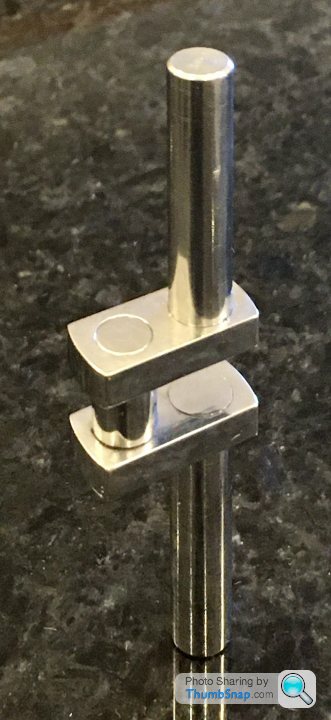
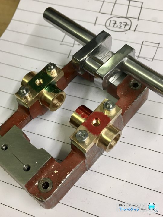
Main components ready for assembly:
And Loctited together:
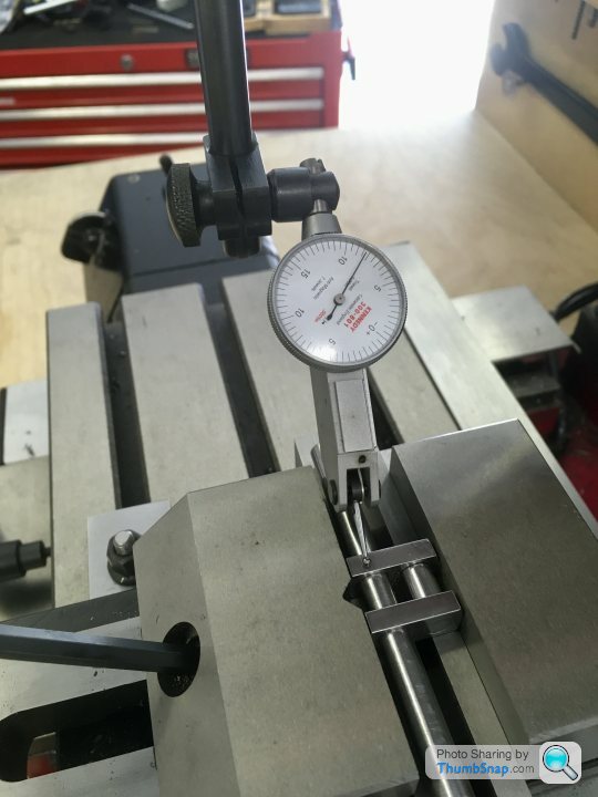
Now re-set in the vice and check for level:
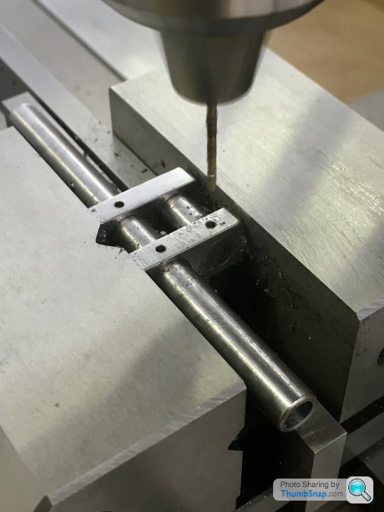
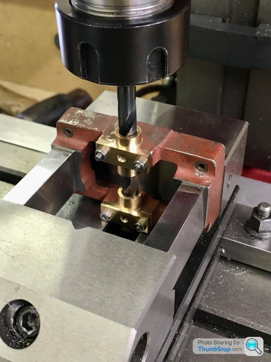
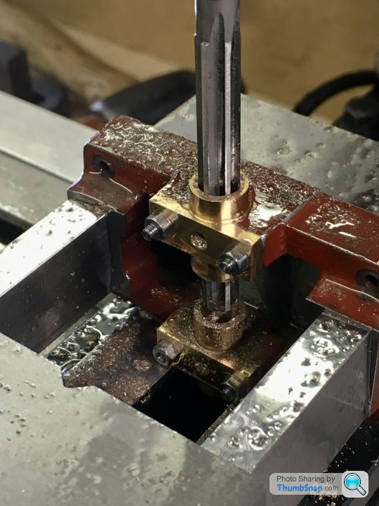
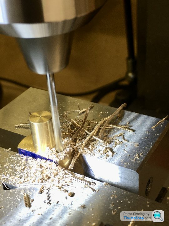
And co-ordinate drilled the pin holes:
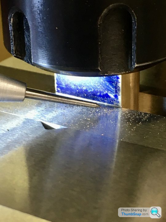
Tapped the Loctite-coated pins in with a hammer, and flatted and polished back:
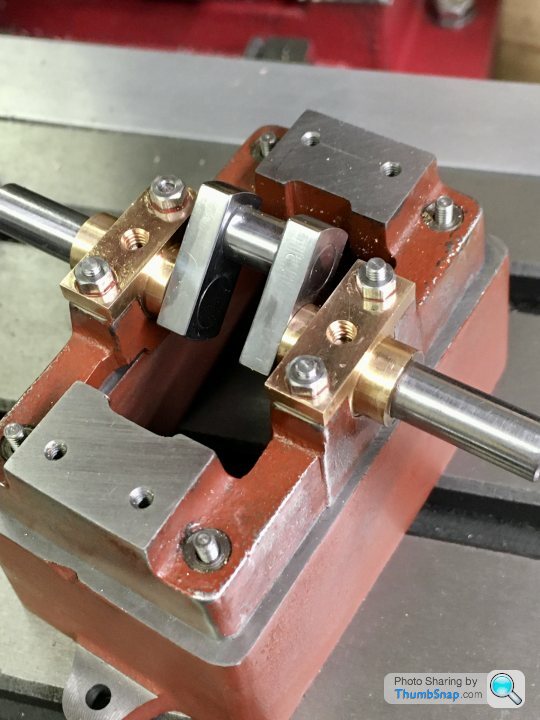
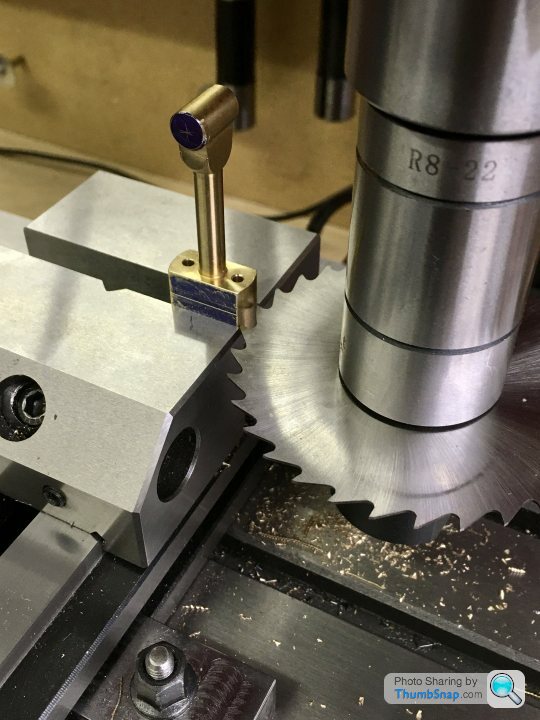
Then put back in the vice, dropped onto a pair of parallels. The sacrificial part of the main shaft was then carefully milled away:
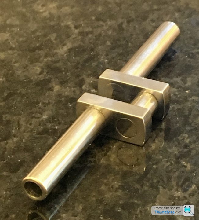
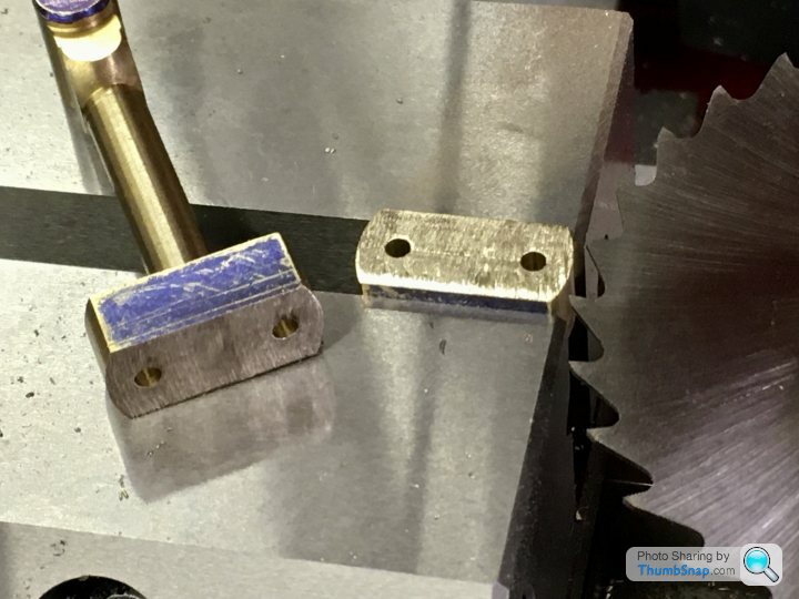
That completed the crankshaft:
So second time around it worked fine.
First job - Loctite two pieces together:
Then fly-cut the edges to clean them up a fraction to be perfectly flat and parallel:
Mill the ends to be square:
Mark out, then put in the vice and check for level:
Co-ordinate drill/ream the holes, having first used the edge finder to get the datums. This time I used the marking out as a double-check:
Then used the nut and bolt method to turn the end radii:
Then machined the main shaft. Not sure why there’s a hole in one end, but it’s on the drawing:
Main components ready for assembly:
And Loctited together:
Now re-set in the vice and check for level:
And co-ordinate drilled the pin holes:
Tapped the Loctite-coated pins in with a hammer, and flatted and polished back:
Then put back in the vice, dropped onto a pair of parallels. The sacrificial part of the main shaft was then carefully milled away:
That completed the crankshaft:
So second time around it worked fine.
Then straight on to fitting the crankshaft to the bearings.
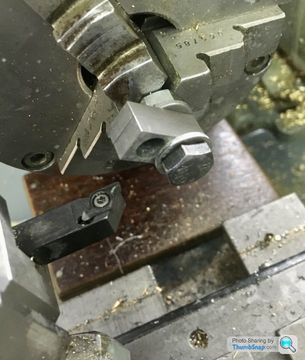
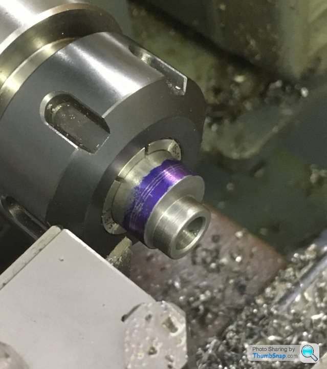
Began by aligning the assembled bearings into the vice using the drill I used to bore them undersized:
Then substituted it with the pre-ream drill:
Then the reamer:
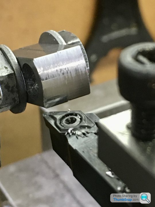
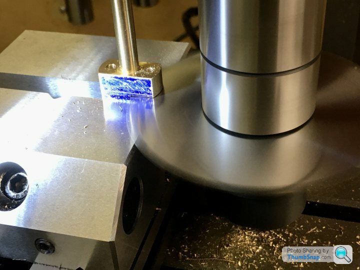
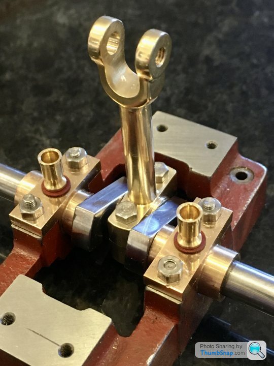
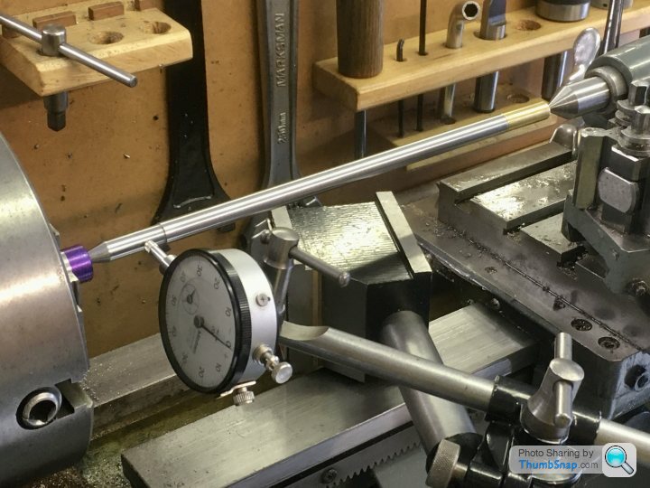
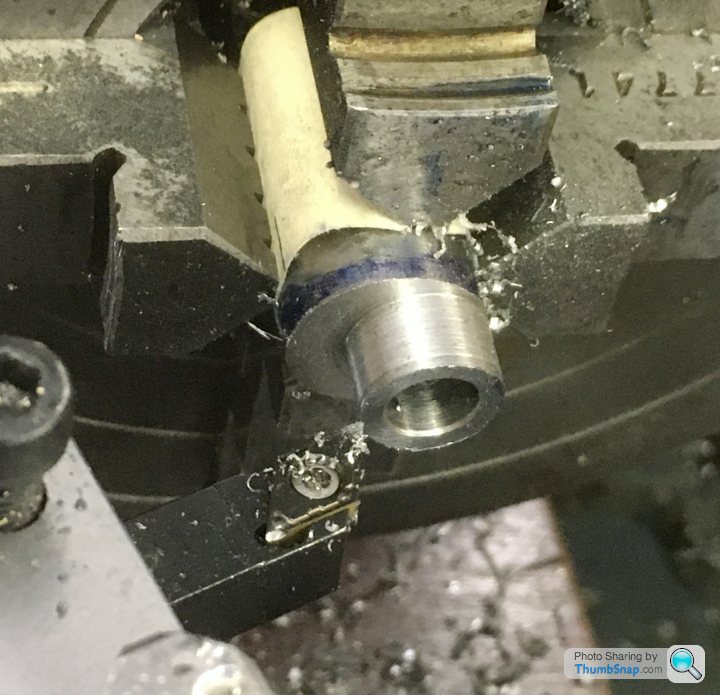
Then sized the bearing thrust faces by trial and error turning in the lathe. I should probably have used an expanding mandrel, but the collet chuck seemed to work well enough. The crank pin is now central in the sole plate (let’s hope it’s also aligned correctly under the cylinder bore axis):
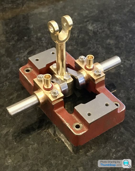
It all fitted together well enough:
No side play, and after test-fitting the flywheel, it spins as smooth as silk:
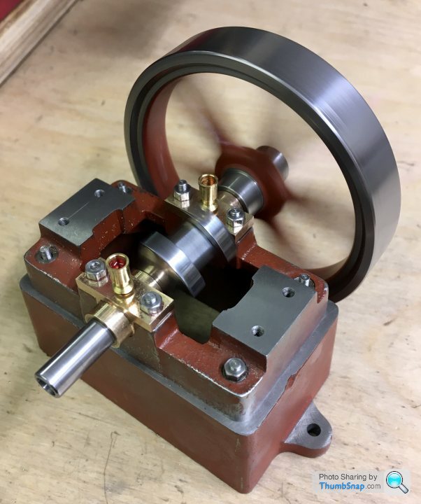
I’m pretty satisfied with today’s progress.
Began by aligning the assembled bearings into the vice using the drill I used to bore them undersized:
Then substituted it with the pre-ream drill:
Then the reamer:
Then sized the bearing thrust faces by trial and error turning in the lathe. I should probably have used an expanding mandrel, but the collet chuck seemed to work well enough. The crank pin is now central in the sole plate (let’s hope it’s also aligned correctly under the cylinder bore axis):
It all fitted together well enough:
No side play, and after test-fitting the flywheel, it spins as smooth as silk:
I’m pretty satisfied with today’s progress.
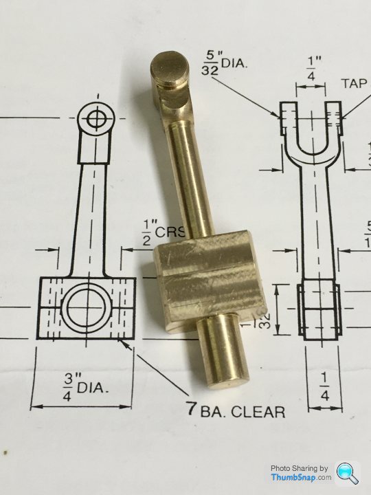
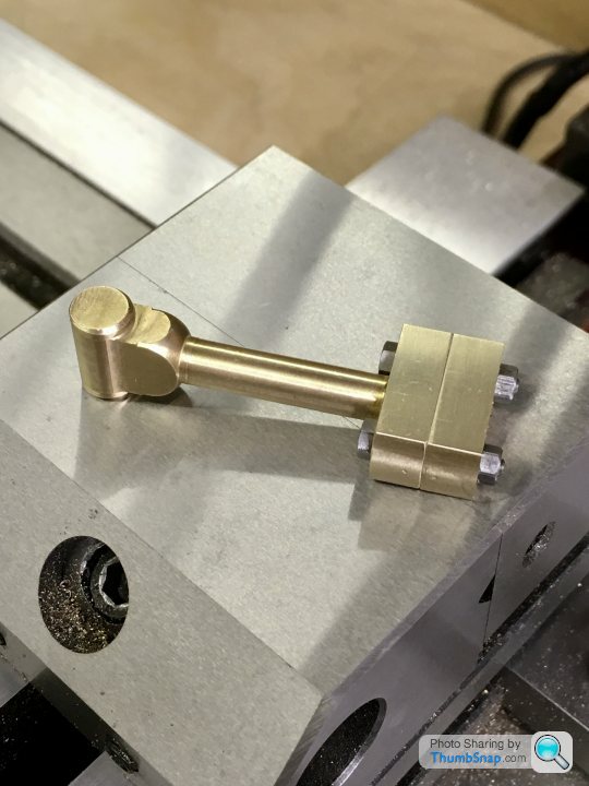
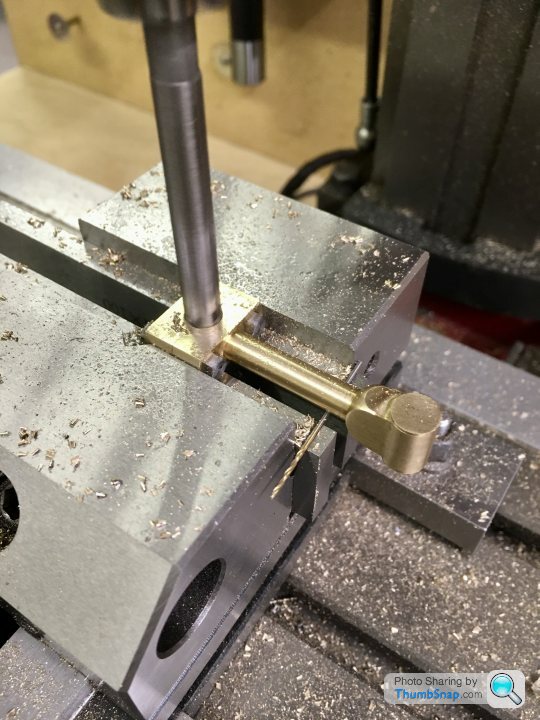
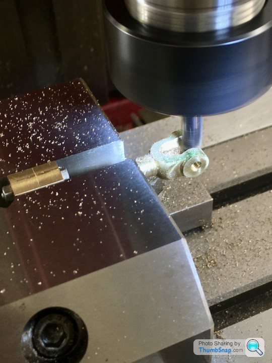
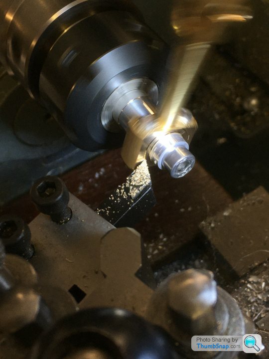
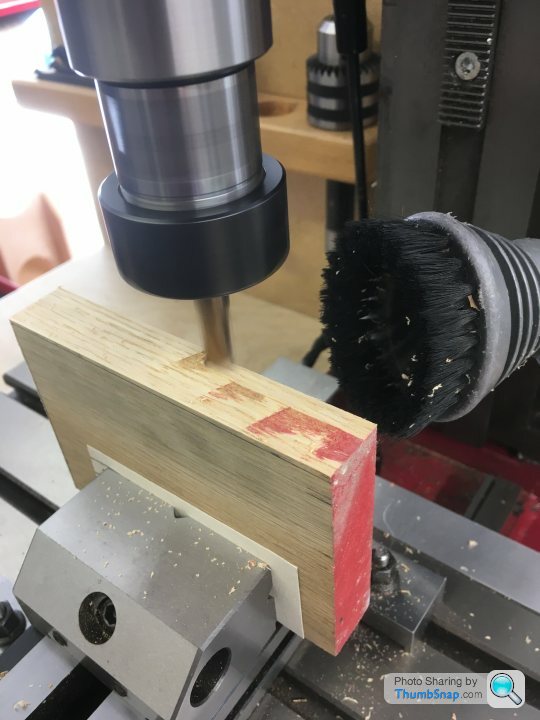
Connecting rod next. I believe it used to be supplied as a stamping, but now it’s a rough-machined item:
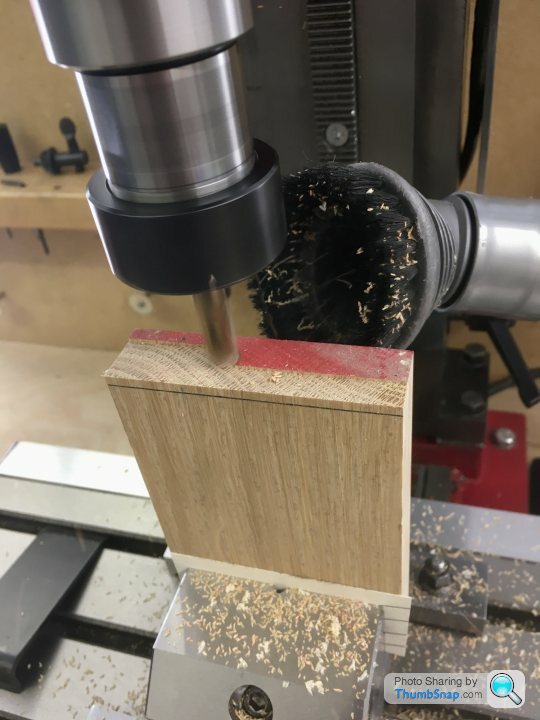
For some reason, it’s got a spigot on the back. I used it to locate in the mill collet, and then lowered into the vice in preparation for drilling the bolt holes. I clocked it up beforehand to check it was straight; it wasn’t bad, a few thou runout:
And again in the vice to check all the accessible surfaces were square:
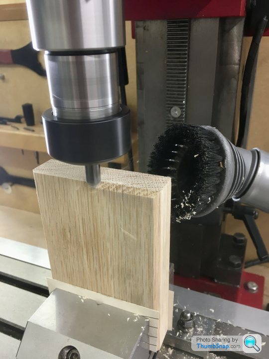
I then used the edge finder to centre the spindle:

Then co-ordinate drilled the holes. I used a smaller drill than specified in order to get a tighter fit:
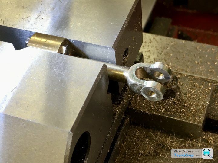
Then removed from the vice, marked out the split line, and the-fitted in the vice to check its level:
Then used the thin slitting saw to cut the lower block:
Then cleaned up the mating faces with an end mill:
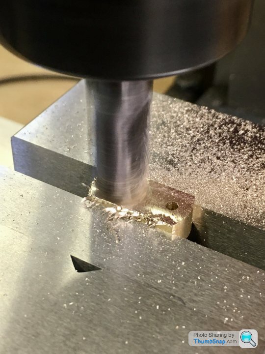
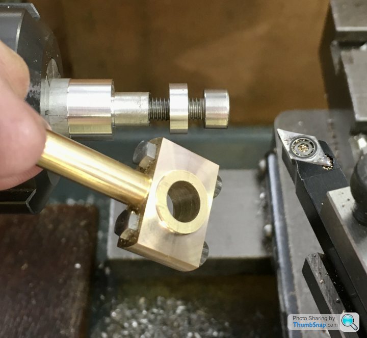
And removed the spigot from the lower block and milled to the correct depth:
Bolted together and Loctited, the sides were milled to the right thickness to fit between the crank webs:
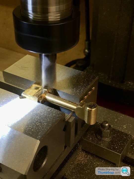
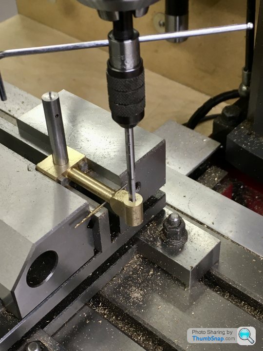
And the small end faces. A bit of vibration here, but I couldn’t think how else to hold it to drill bothe ends in the same setup:
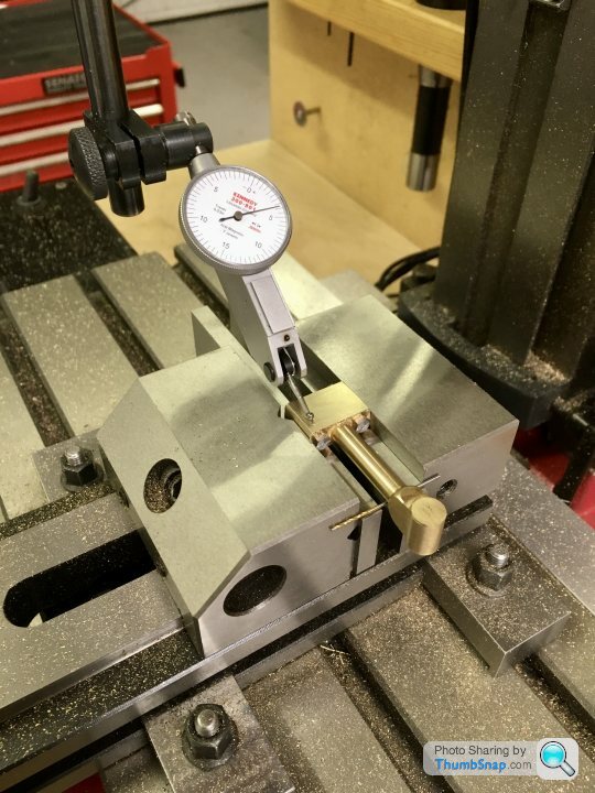
Then double checked the main faces for flatness in two planes:
Then got the centre point for the crank pin hole bang on the cut line:

Drilled and reamed:
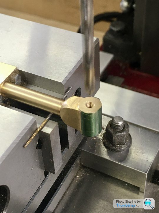
Then on to the small end. Through drilled and tapping to 5BA:
And in the same setup, drilled and reamed half way to pin size (removing the upper threads in the process):
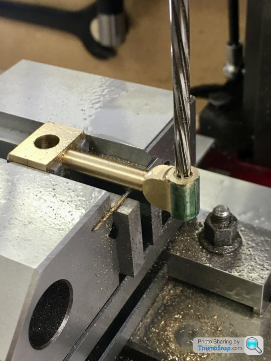
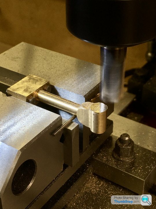
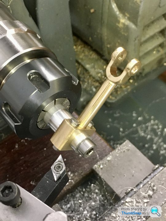
Next job was to measure and open out the forked end by milling:
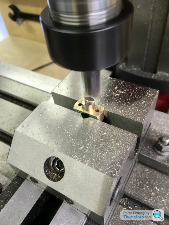
Final job was to machine the cheek bosses. I made a simple fixture out of aluminium. The end boss is a clamp and a diameter reference:

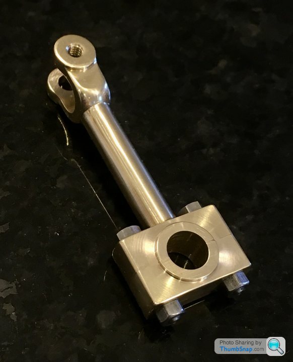
So after a quick polish, that’s another bit done:


On assembly, there was a slight resistance to turning in a couple of spots, but working with a drop of light oil soon had it working smoothly with no side play at all:
The sides of the bearing block are very close to the sole plate, but are in fact under-sized to the drawing. The slider stamping that the forked end locates around is also undersized slightly as supplied. Bit of a shame Because I could have narrowed the fork. It’s only a slight bit of play though, and I may well need it once assembled...
For some reason, it’s got a spigot on the back. I used it to locate in the mill collet, and then lowered into the vice in preparation for drilling the bolt holes. I clocked it up beforehand to check it was straight; it wasn’t bad, a few thou runout:
And again in the vice to check all the accessible surfaces were square:
I then used the edge finder to centre the spindle:
Then co-ordinate drilled the holes. I used a smaller drill than specified in order to get a tighter fit:
Then removed from the vice, marked out the split line, and the-fitted in the vice to check its level:
Then used the thin slitting saw to cut the lower block:
Then cleaned up the mating faces with an end mill:
And removed the spigot from the lower block and milled to the correct depth:
Bolted together and Loctited, the sides were milled to the right thickness to fit between the crank webs:
And the small end faces. A bit of vibration here, but I couldn’t think how else to hold it to drill bothe ends in the same setup:
Then double checked the main faces for flatness in two planes:
Then got the centre point for the crank pin hole bang on the cut line:
Drilled and reamed:
Then on to the small end. Through drilled and tapping to 5BA:
And in the same setup, drilled and reamed half way to pin size (removing the upper threads in the process):
Next job was to measure and open out the forked end by milling:
Final job was to machine the cheek bosses. I made a simple fixture out of aluminium. The end boss is a clamp and a diameter reference:
So after a quick polish, that’s another bit done:
On assembly, there was a slight resistance to turning in a couple of spots, but working with a drop of light oil soon had it working smoothly with no side play at all:
The sides of the bearing block are very close to the sole plate, but are in fact under-sized to the drawing. The slider stamping that the forked end locates around is also undersized slightly as supplied. Bit of a shame Because I could have narrowed the fork. It’s only a slight bit of play though, and I may well need it once assembled...
Edited by dr_gn on Friday 18th September 21:40
Not quite finished the eccentric strap yet - I’ve got to drill the oil hole, but can’t figure out how to do it:

There’s not enough clearance for a chuck. I was considering putting it at the other side of the stem, at 45 degrees to give myself room for the chuck, but Id like to know how to do it as per the drawing.
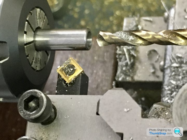
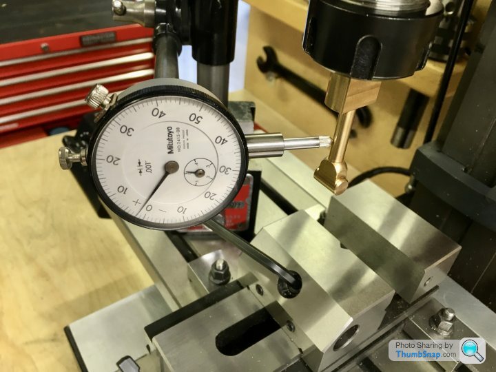
So I got on with the eccentric itself. The steel provided in the kit Is the correct o/d, so with that in mind, I faced it in the lathe:
Then transferred to the mill and got the centre with the edge finder:
Then offset the x-axis by the eccentric throw, and centre drilled:

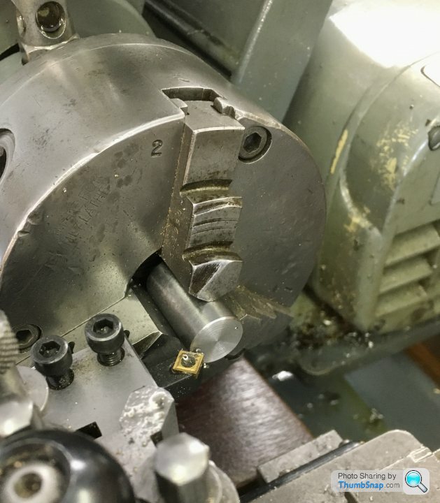
Then back to the lathe and set it in the 4-jaw chuck, centred on the offset hole:
Drilled and reamed to size:

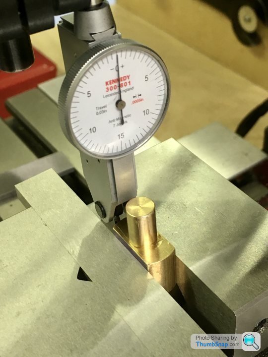
Then turned the spigot with intermittent cuts:
Marked out for the locating groove:
and then cut the groove with a ground down old HSS parting tool:

I started to part it off:

Then realised that because the hole is offset, it would break through at one side, and the process wouldn’t work. So I removed from the chuck and centered it on the hole again, meaning intermittent cuts for parting off:
It worked ok, but I found this material very difficult to work with . It seemed very tough, and turning tended to gouge the surface. I cleaned it up by making a wooden block and coating the face with SiC, and abraded the marks out by turning. A bit like lapping, but on the face.
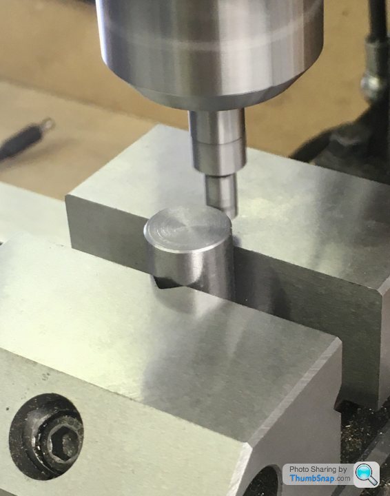
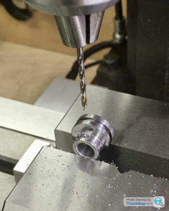
Finally, the screw hole. I set it up on the mill, getting the high point with a finger gauge:

Then drilled and tapped without any issue:
Finished, although it is a bit crunchy when rotated in the strap. No idea why.
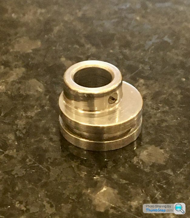

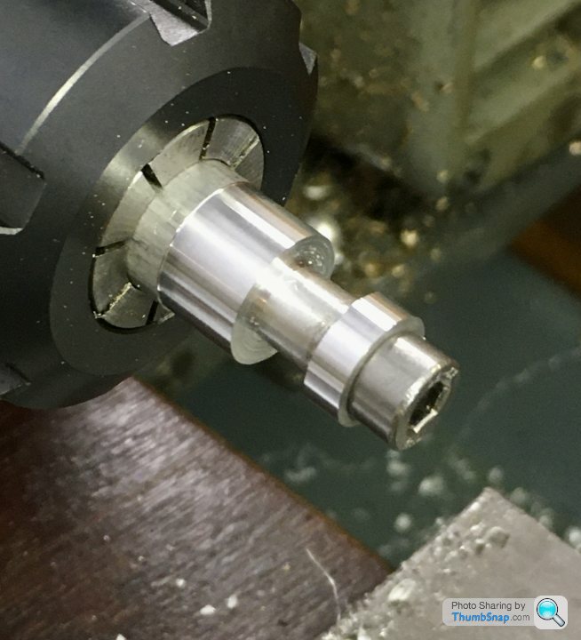
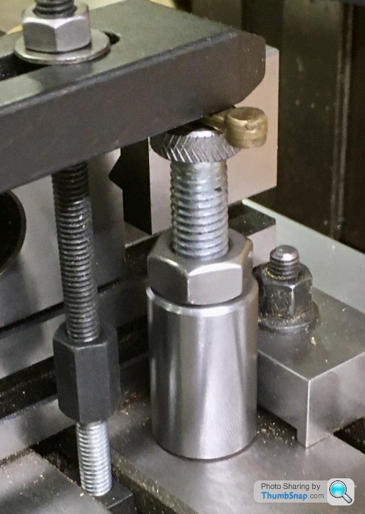
Also tidied up a few loose ends, like making an expanding mandrel and facing the main bearing external faces to length:

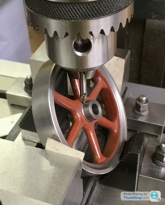
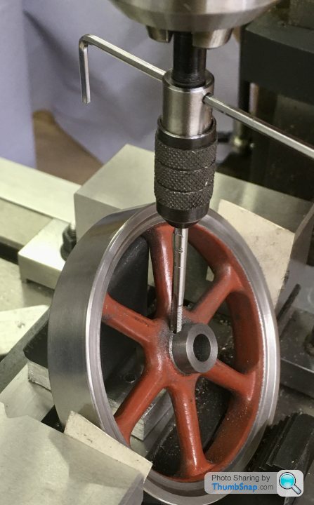
Again using the mandrel, facing the flywheel bosses to length, then mounting on the mill and drilling and tapping the screw hole:
And finally, machining the eccentric strap stepped locating bolt:

Not the best fit in the groove -a bit loose - but I found it difficult to get it right. Might have another go at that sometime.
There’s not enough clearance for a chuck. I was considering putting it at the other side of the stem, at 45 degrees to give myself room for the chuck, but Id like to know how to do it as per the drawing.
So I got on with the eccentric itself. The steel provided in the kit Is the correct o/d, so with that in mind, I faced it in the lathe:
Then transferred to the mill and got the centre with the edge finder:
Then offset the x-axis by the eccentric throw, and centre drilled:
Then back to the lathe and set it in the 4-jaw chuck, centred on the offset hole:
Drilled and reamed to size:
Then turned the spigot with intermittent cuts:
Marked out for the locating groove:
and then cut the groove with a ground down old HSS parting tool:
I started to part it off:
Then realised that because the hole is offset, it would break through at one side, and the process wouldn’t work. So I removed from the chuck and centered it on the hole again, meaning intermittent cuts for parting off:
It worked ok, but I found this material very difficult to work with . It seemed very tough, and turning tended to gouge the surface. I cleaned it up by making a wooden block and coating the face with SiC, and abraded the marks out by turning. A bit like lapping, but on the face.
Finally, the screw hole. I set it up on the mill, getting the high point with a finger gauge:
Then drilled and tapped without any issue:
Finished, although it is a bit crunchy when rotated in the strap. No idea why.
Also tidied up a few loose ends, like making an expanding mandrel and facing the main bearing external faces to length:
Again using the mandrel, facing the flywheel bosses to length, then mounting on the mill and drilling and tapping the screw hole:
And finally, machining the eccentric strap stepped locating bolt:
Not the best fit in the groove -a bit loose - but I found it difficult to get it right. Might have another go at that sometime.
I noticed your excentric strap issues, but not sure how far you have already gone into the machining process, as ideally before the top surface of the excentric strap on the bolted side is reduced down, then you: clamp the strap vertically; file a small flat (but within what you will take away later on finishing) and center punch the hole centre, by hand. Then carefully using a long drill bit (to get the chuck above the top of the excentric strap), drill the hole vertically down. If you don't have a long drill set, then an extension with a collar can be made just make the hole in the end to hold the drill bit an interfearance fit, heat the collar sligthy and pop the drill bit in the freezer, then insert the drill bit and let them normalise. You can then heat the collar afterwards to retrieve the drill bit. Alternatively use the same drill to drill a hole in the extension and then loctight it in place, but then you loose the drill bit. As seen there is not enough room for a centre drill, unless you can find some of the long ones, which i have not seen for a very long time. For the conical part of the oil resevoir, i suggest a taper reamer and then hand finishing the flare with a small burr or such. Very much enjoying the project and your updates.
Gassing Station | Scale Models | Top of Page | What's New | My Stuff