Stuart 10V Vertical Steam Engine
Discussion


dudleybloke said:
Lovely work there, very neat and tidy.
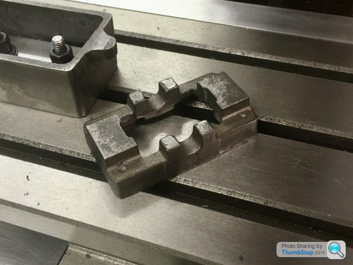
Thanks. I sometimes think of the fantastic (and prolific) work turned out by the old hands in their workshops, where it looks like a bombs hit it. I guess if you're busy actually making things, your workshop can get very messy. I just can't work like that for some reason. Even with plastic or card modelling, I pack everything away after each session. For me, a clean start every time is beneficial. Even so, within 1/2 hour of starting a job, pretty much every tool I own seems to be strewn over every available surface (often including the floor).Just finished making the first of four vice clamps.


While I can't be too disappointed with it as a first attempt at milling, I'm not sure about the surface finish. I'm getting a series of shallow swirls (which isn't an real issue), but also shallow ridges along one side of the feed lines. I buffed the part using a wheel, and it got most of the ridges out, but I really want to sort this before attacking a 10V casting.
I guess it could be a result of poor tramming. I have trammed the mill by shimming the column the best I can; I'm getting about 0.002" front to back and side to side on bed, over a radius of about 300 mm. I can't seem to get much better than that. I'm also having trouble adjusting the gibs - very tricky to know how tight is right. Anyway, hopefully by trial and error on adjustments I'll make incremental improvements.
BTW the DRO's are great, especially in conjunction with a Starrett edge finder. Not sure I'd be able to cope without those things, what with the massive amount of backlash on all the handwheels.
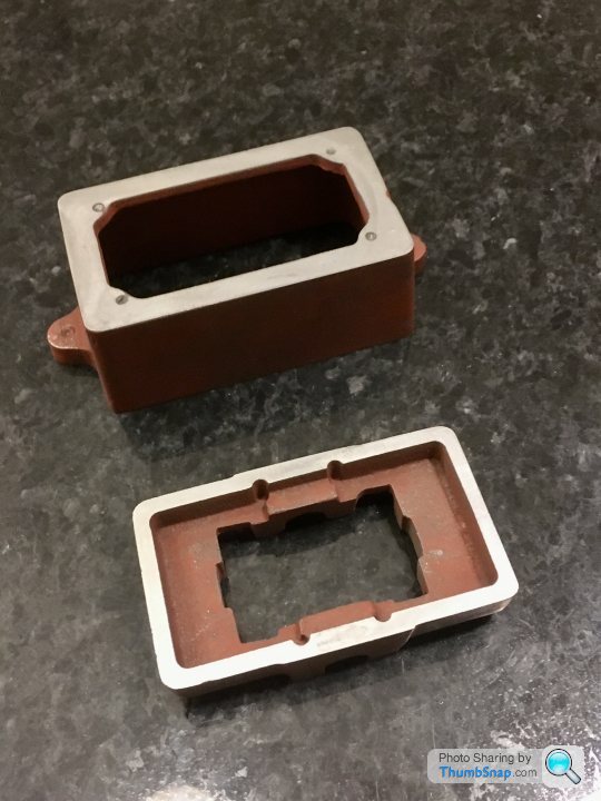
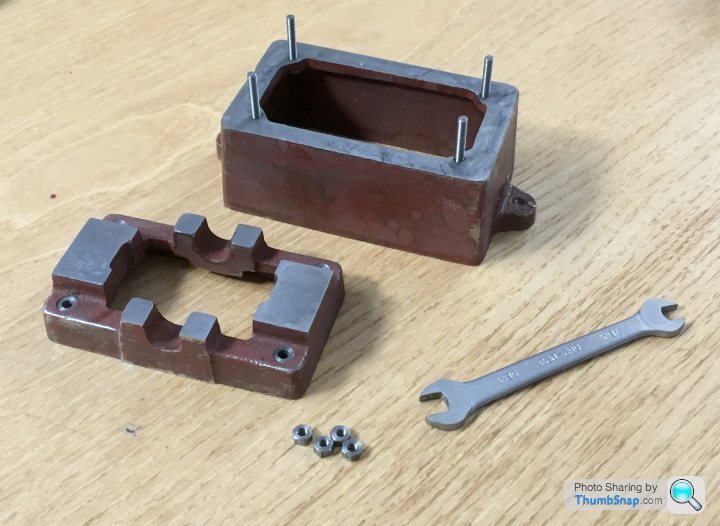
So today was the anniversary of getting the kit, so I made a start. I’m still not confident enough to use the milling machine on a casting; I want to try different tooling first on the remaining vice clamps. First job was cleaning up the box base and sole plate casting using files and abrasive paper on a surface plate:
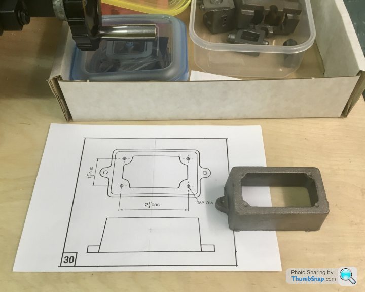
I don’t have a vernier height gauge, so I did a quick check with a height scriber and my digital callipers:
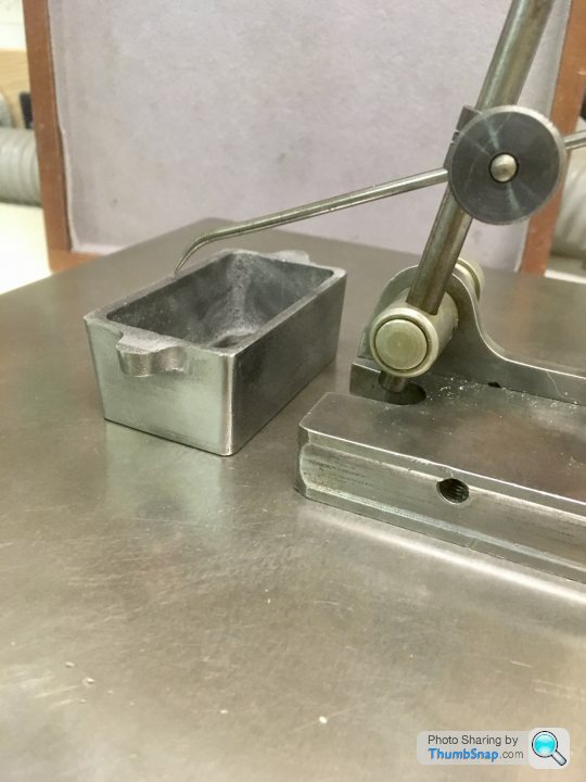
The box bed seemed pretty much spot on, so just needs a few clean-up passes. The sole plate had an approx. 0.3mm high spot at one end, but that will disappear when it’s machined to the correct height.
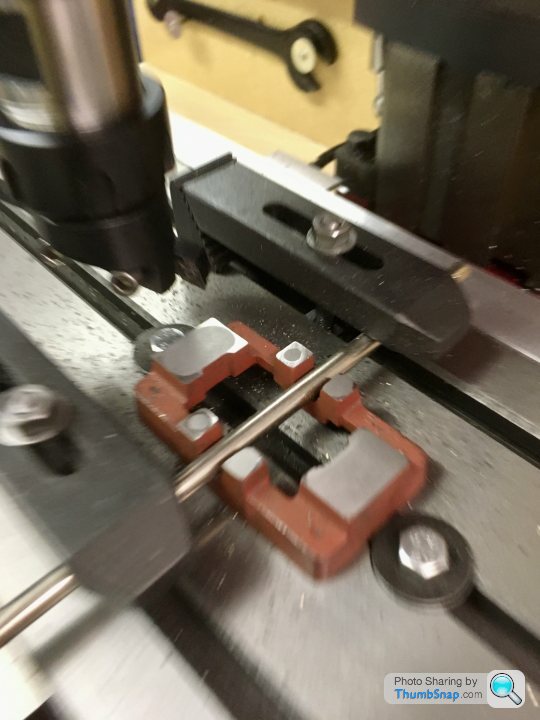
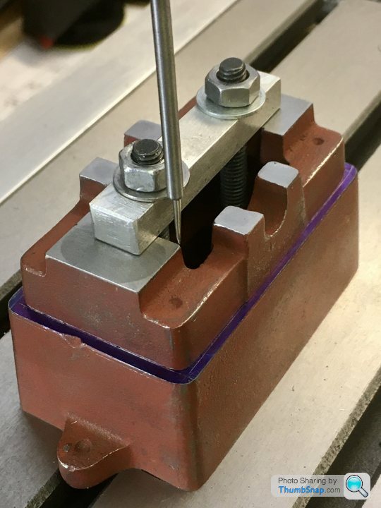
I made a clamp plate for the box bed out of some unhardened tool steel. I face-milled the long sides, and tried side-milling the short edges, but it didn’t work out well at all. Side milling was pretty hopeless on the vice clamps too. No idea why. Ended up mounting on its ends and end milling those too. Used the edge finder and DRO’s to get the hole positions. A bit OTT for a simple fixture, but I need as much practice as I can get:

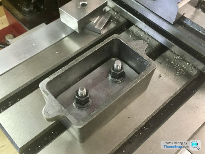
I’ll clamp the sole plate using an old screwdriver and various clamps to keep it in place:
I don’t have a vernier height gauge, so I did a quick check with a height scriber and my digital callipers:
The box bed seemed pretty much spot on, so just needs a few clean-up passes. The sole plate had an approx. 0.3mm high spot at one end, but that will disappear when it’s machined to the correct height.
I made a clamp plate for the box bed out of some unhardened tool steel. I face-milled the long sides, and tried side-milling the short edges, but it didn’t work out well at all. Side milling was pretty hopeless on the vice clamps too. No idea why. Ended up mounting on its ends and end milling those too. Used the edge finder and DRO’s to get the hole positions. A bit OTT for a simple fixture, but I need as much practice as I can get:
I’ll clamp the sole plate using an old screwdriver and various clamps to keep it in place:
So a small fly cutter holder arrived today. I put my Sandvik 8mm left hand tool holder in it, fitted with a DCMT 070208 insert for steel, and had a go at fly cutting for the first time. Must say I was really happy with the results, finally a bit of progress. Workpiece was the same mild steel I've been using for the vice clamps. I went up to 0.5 mm cut depth with no issues.
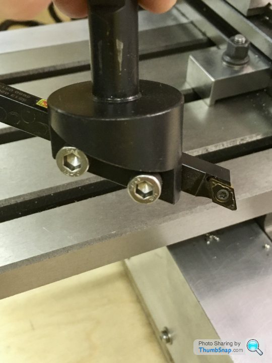
The only slight problem was vibration due to the tool holder being long. I ground it down a bit and that resolved that. The grub screws in the holder appear to be made of cheese, so having got the tool well and truly stuck, I spent a good 30 minutes drilling them out and replacing with caphead screws, which was fun.
Missed the postman due to work, so the milling cutter test will have to wait.
fourfoldroot said:
This is where you find out if the castings have any chilled patches. They will show up as very shiny hard spots when cutting and very quickly wreck the milling cutters. I had quite a few spots on my stuart kit. If you have a log burner, put them in a good hot fire and leave them to cool overnight,they should be easily machinable by morning. First time I did it I discovered a blob of melted metal which I thought was the casting and panicked! Fortunately it was just something in the scrap wood I usually burn. A bit of scrobbling around and I found the perfectly intact softened casting. I’m making a beam engine at the moment from vintage Clarksons castings and they are terrible. All the iron ones have been in the log burner for softening and relaxing!
I made a few sparks with the fly cutter today - closer inspection showed some discolouration on one edge of the test piece, and some weld spatter - or it might have been flame cut or something. I think it was the HAZ that was harder then the base metal. I've filed the castings, where they will be machined, and not found any hard spots so far. I'll only be taking very light cuts, so hopefully I'll be OK. Not sure whether to mill the box and bed faces or fly cut them with my new toy.
Thanks.
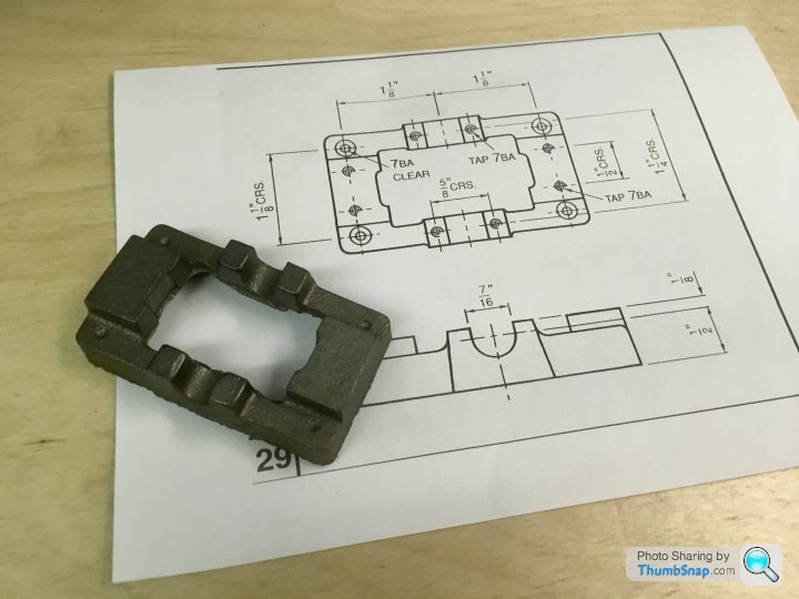
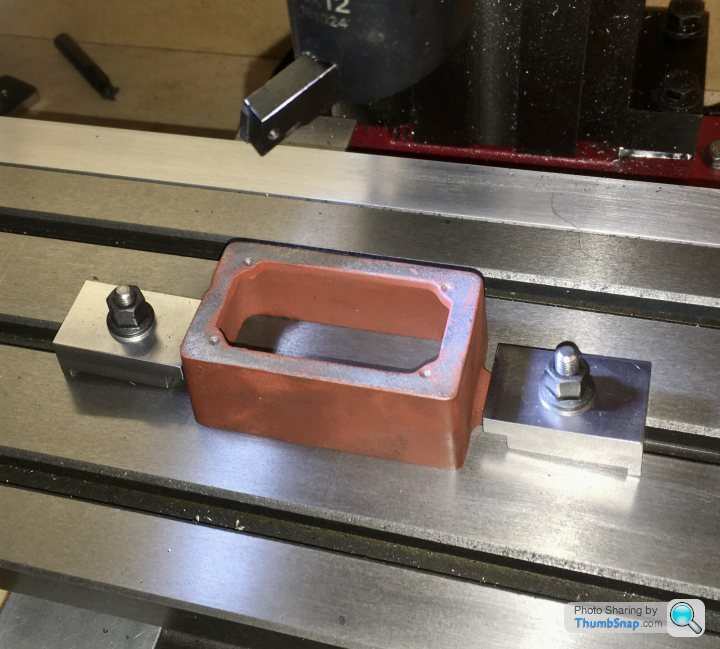
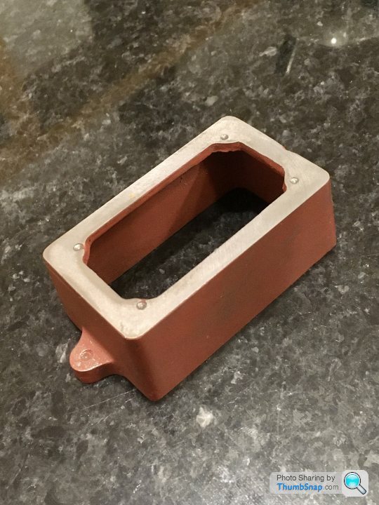
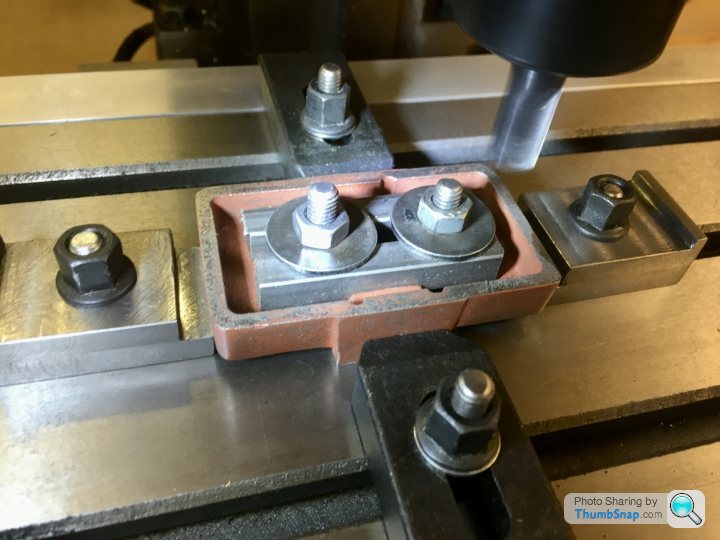
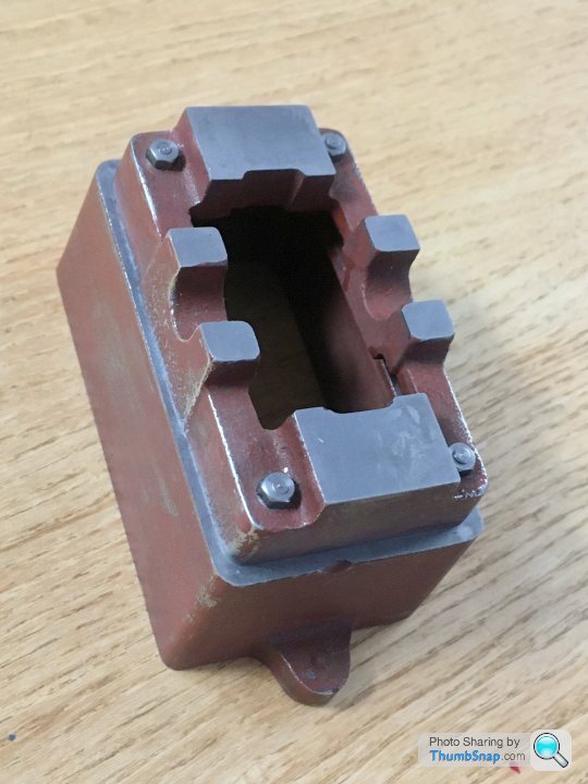
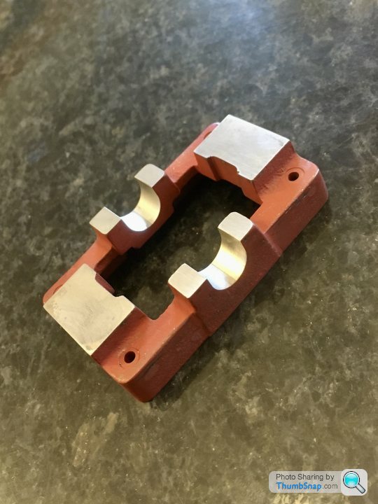
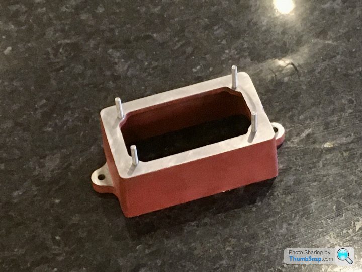
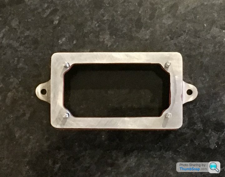
Finally took the plunge and machined my first casting. Nothing spectacular, but it feels like a big step for me. I opted to use the fly cutter with an insert for cast iron, mainly because it's by far the best method I've used for getting a good finish. I used my fixture plate for one side, and the remaining two vice clamps (finished this evening) for the other. There's no height specified on the drawing, so I just did the mimimum clean-up. I think the different colours through the wall must be something to do with how the metal cooled:

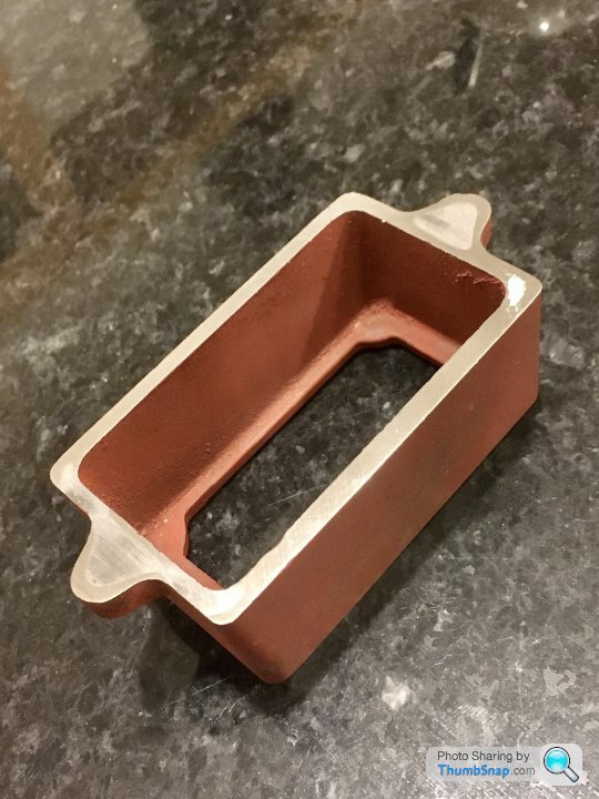
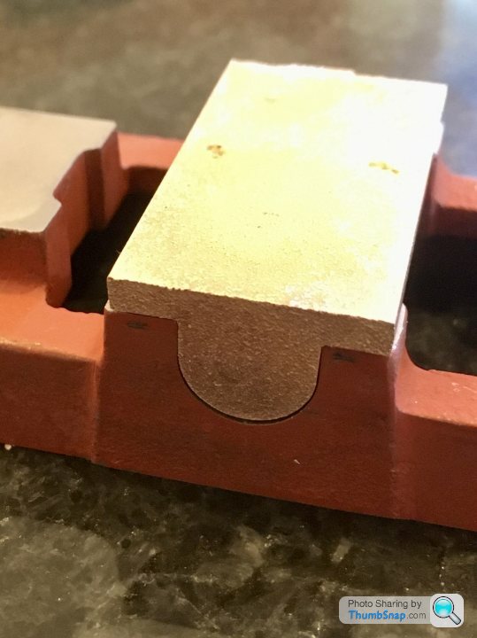
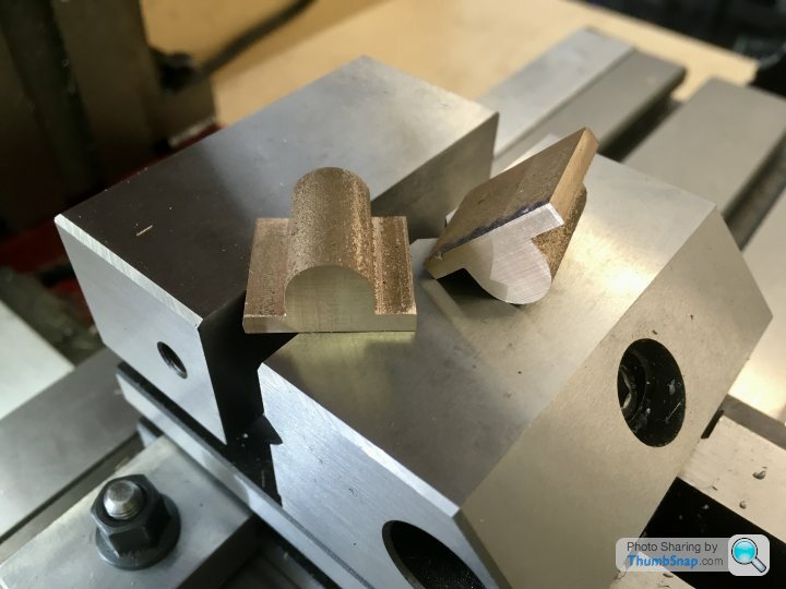
Moving on a few stages, I bought a 7/16" (0.4375") Ball Nose end mill, with the intention of using it to make the 7/16" wide slots for the main bearings, as specified on the drawing. The brass casting supplied is actually a bit smaller than 7/16", at 0.4285" wide. The cutter itself measures approx. 0.4350" according to my verniers, and made the same width slot in some aluminium I used as a test:
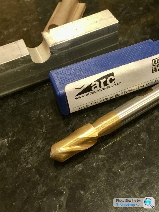
However, it appears that the radus of the ball end of the cutter is not tangential to the flanks:
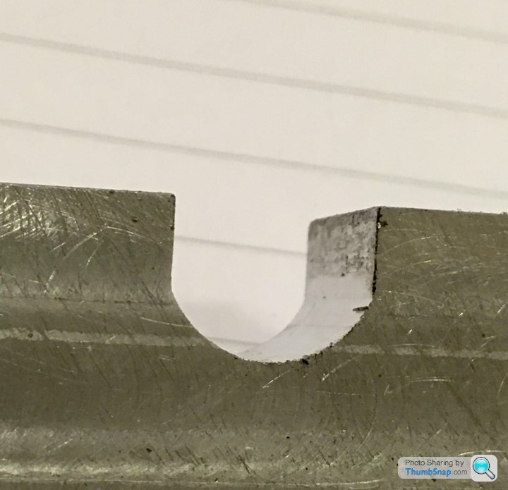
It's quite pronounced. I cut the test slot to the correct depth, and this is the fit I get with the brass:

Although it's not necessary for a perfect fit, I could have done significantly better with a file.
Moving on a few stages, I bought a 7/16" (0.4375") Ball Nose end mill, with the intention of using it to make the 7/16" wide slots for the main bearings, as specified on the drawing. The brass casting supplied is actually a bit smaller than 7/16", at 0.4285" wide. The cutter itself measures approx. 0.4350" according to my verniers, and made the same width slot in some aluminium I used as a test:
However, it appears that the radus of the ball end of the cutter is not tangential to the flanks:
It's quite pronounced. I cut the test slot to the correct depth, and this is the fit I get with the brass:
Although it's not necessary for a perfect fit, I could have done significantly better with a file.
Edited by dr_gn on Wednesday 13th May 23:54
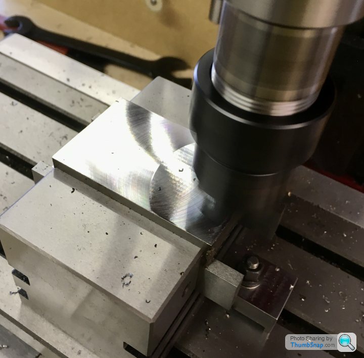
Got the sole plate faced tonight - I used the fly cutter again for the top, and took about 0.35mm off:
After some head scratching, I opted to face mill the underside (-0.35mm) - mainly due to clearance for clamping. Again, no issues at all:
I'm really pleased with the finish. Tomorrow's job will be drilling and tapping the mounting holes.

After some head scratching, I opted to face mill the underside (-0.35mm) - mainly due to clearance for clamping. Again, no issues at all:
I'm really pleased with the finish. Tomorrow's job will be drilling and tapping the mounting holes.
Turn7 said:
ooi, would this kit normally require this amount of fettling, or this just you working to your own very high standards ?
As dhutch says - it’s just a kit of Iron castings, bar stock and nuts and bolts. You have to machine everything from scratch, to the drawings. There are no instructions as such, and nothing you can just assemble from the box. So I set up the box bed and sole plate on the table and best-fit aligned it in x & y using a pointed wiggler and edge finder. I'd already marked out the best-fit outline of the sole plate on the box bed top surface:
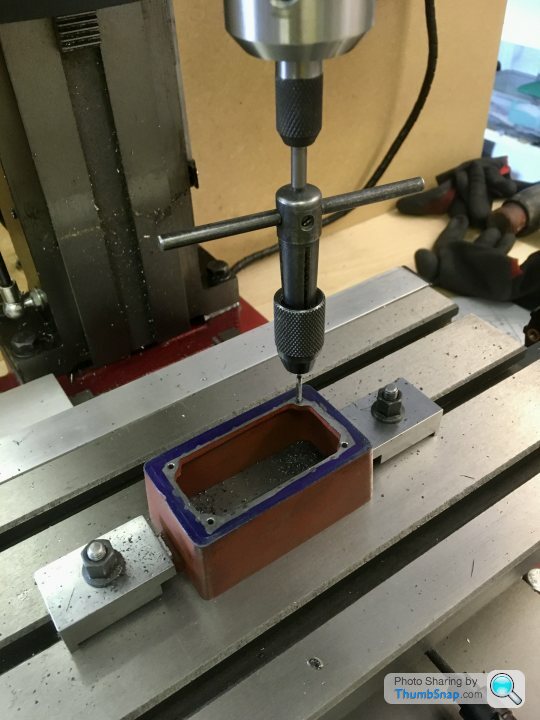
Then drilled tapping holes and clearance holes for the studs, and tapped the box bed:
Everything aligned perfectly, apart from the spot faces I did with a slot drill. Despite using the same co-ordinates as the holes to within 0.01mm, all the spot facings were off-centre (in different directions). Fortunately they were marginal diameter for the nuts, so I can correct them by making a spot facing tool with a spigot to prevent any wandering.
Thanks a Fourfold. The axes were locked in each position. I did a subsequent test in some plain steel and swapped the drills and cutter in a fixed position, but still got offset circles. I think I should have perhaps spot faced first.
Yes, the studs are temporary - I think the actual ones supplied aren’t threaded far enough, so I had to use short ones for a test fit. I will make sure there are equal protrusions.
BTW the tap wrench in the photo is held exactly vertical over the hole with a spring-loaded centre held in the chuck. The studs are a close clearance fit in the sole plate holes, but it drops straight on, so at least that worked!
ETA I didn’t do all the operations for one hole at a time because I wanted to use the z depth stop for clearance drilling (just until the box bed surface), and more importantly to get the spot faces the same height above the base datum. If I was replacing drills etc there was no guarantee to fit them back at the right height. It did work, but no idea if it caused me the issue with off centres. Anyway, that was my reasoning.
Edited by dr_gn on Friday 15th May 22:53
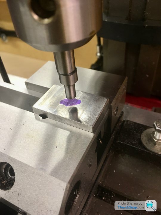
So after the false start trying to mill the main bearing recesses with the wrongly profiled tool, I tried again with a slightly smaller one (11mm, not 7/16”), and much better quality. Tested in aluminium:
Perfect, so on to the real thing:
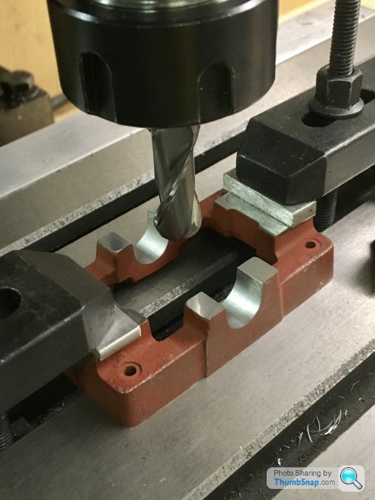
Went through the casting like it was butter. Unfortunately I centred the casting on the inner edges of the standard flats, double checking it with the insides of the cast bearing housing prongs. Result is that the brass is slightly offset to one side (but centred on the inside edges of the base). I should have used the outside edges of the bearing housing prongs.
Anyway a few passes with a fine file and it’s not really apparent, but lesson learned.
Onwards...
Perfect, so on to the real thing:
Went through the casting like it was butter. Unfortunately I centred the casting on the inner edges of the standard flats, double checking it with the insides of the cast bearing housing prongs. Result is that the brass is slightly offset to one side (but centred on the inside edges of the base). I should have used the outside edges of the bearing housing prongs.
Anyway a few passes with a fine file and it’s not really apparent, but lesson learned.
Onwards...
So today I re-made the spot facing tool, this time in Silver Steel from M-Machine, rather than Stainless (which I used by mistake last time). I've put all my known and marked steels in a box, the rest I've kept in reserve in 'deep storage' (the shed) just in case.

Made a jig for the milling machine to make the tool more acurately than I could by eye:
Then hardened by getting cherry red and dunking in brine:

Made a brass spigot this time, to keep everything concentric:
The test:

Perfect!

Also separated the main bearing stock and faced them off with my new ARC premium mill, which performed beautifully:

Made a jig for the milling machine to make the tool more acurately than I could by eye:
Then hardened by getting cherry red and dunking in brine:
Made a brass spigot this time, to keep everything concentric:
The test:
Perfect!
Also separated the main bearing stock and faced them off with my new ARC premium mill, which performed beautifully:
Still puzzling over how to retain the bearings on a mandrel and how to make a centering bar, so in the meantime I thought I'd finish the box bed. The mounting lugs are cast with dimples to drill to, but they didn't look central to me, and since thre are no dimensions given on the drawing I just got one with it the best I could.
I trued the casting up with a DTI along its long egde, and then milled 0.8mm off the top surfaces of the mounting lugs. I used 0.2mm cut depths. I did the side-to-side cuts by eye. A 12mm end mill covered the width of the lugs in one pass.
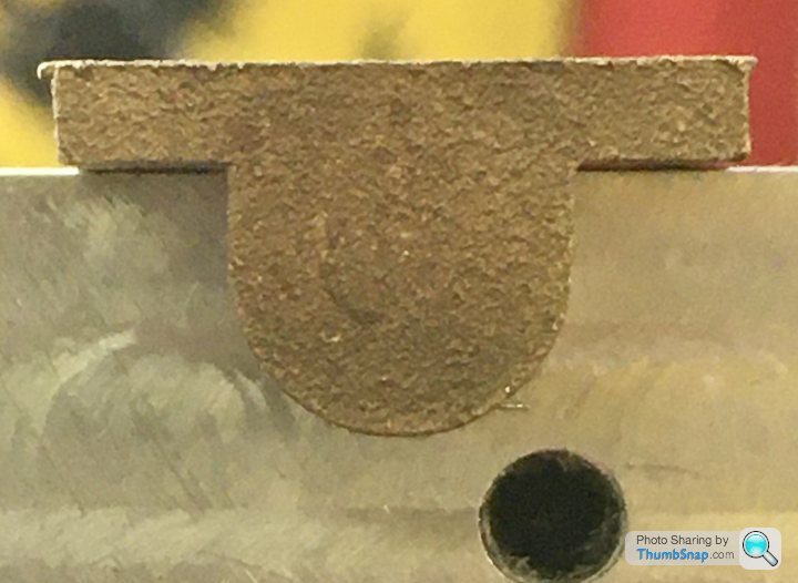
I wanted to get the mounting holes concentric with the end radii of the lugs, and since the cast radius doesn't cover 180 degrees, I opted to find a washer that was a good fit, and measure the diameter of that:

Then a fairly simple task of finding the middle of the casting, and using the edge finder to find the apex of the radius, then move to the centre using the DRO, centre & and drill to 3.5mm diameter:

Worked OK:
Pretty basic stuff, but one step further on.
I trued the casting up with a DTI along its long egde, and then milled 0.8mm off the top surfaces of the mounting lugs. I used 0.2mm cut depths. I did the side-to-side cuts by eye. A 12mm end mill covered the width of the lugs in one pass.
I wanted to get the mounting holes concentric with the end radii of the lugs, and since the cast radius doesn't cover 180 degrees, I opted to find a washer that was a good fit, and measure the diameter of that:
Then a fairly simple task of finding the middle of the casting, and using the edge finder to find the apex of the radius, then move to the centre using the DRO, centre & and drill to 3.5mm diameter:
Worked OK:
Pretty basic stuff, but one step further on.
fourfoldroot said:
I drilled and reamed bearing moulding, the cut slightly oversize each bearing. Then finished ends and shoulders on a tapered mandrel. To make tapered mandrel set topslide over to cut a teeny taper. That is enough to hold the bearing whilst you trim them. The brass cuts easily enough, you can superglue them if they are slipping. Don’t tap and drill bearing mounts until you have crankshaft, tap and drill with bearings on it to allow for alignment. Helps a bit if the u-channel is a bit not perfect!!
Thanks for that FFR. I've seen a slightly simpler method on the ME forum, where you turn the mandrel to a transition fit, and wring the bearing onto it. Then you apply clamp force with a caphead bolt at the end. Seems straightforward, so I might try that. Of course you can't turn between centres, but the overhang is very short, and the bosses I'm turning dot realy do much in terms of needing concentricity. I'm not even sure I could re-align the tailstock again if I moved it!The crankshaft rod is supplied, and since I'm line reaming the fitted bearings as a pair, they shouldn't need any wiggle room; once theyre screwed down and reamed, that's it as far as alignment goes. When the bearings are removed for assembly, the crankshaft itself should re-align them assuming any slight play in the milled recesses. Obviously I'll mark the bearings so they go back in the same place.
At least that's the theory!
fourfoldroot said:
As you have said previously, there is many ways to skin a cat. I wouldn't offset the tailstock as it's a nuisance to reset. It's all about problem solving. Once you have done a build with words and music it gives you the confidence to tackle another project with your own ideas. There is no right way, but what works for you. The 10V is quite forgiving but has a few hard bits. I made three crankshafts before I got it right, eventually turning it from plate steel. Drilling the steam chest valve rod was an absolute pig, wandering drill points being the problem. If it was easy it wouldn't be satisfying.
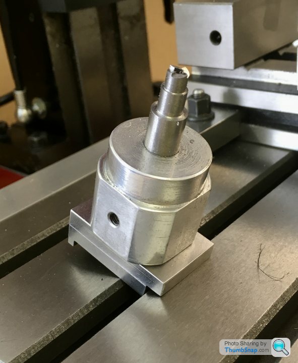
Yes, the more I read ‘how to build the 10V”, the more confusing it gets. It’s difficult to judge the result from videos or photos in terms of how well they run too.So thinking about the process of machining the bearings - I’ve got to turn bosses of different lengths on each end. It’ll be an intermittent cut from the outer ‘wings’ to the solid inner, so I’ll be moving the cross-slide in, cutting towards the Chuck, backing off, then incrementing the cross-slide in again before making another cut towards the Chuck.
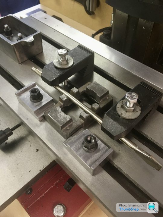
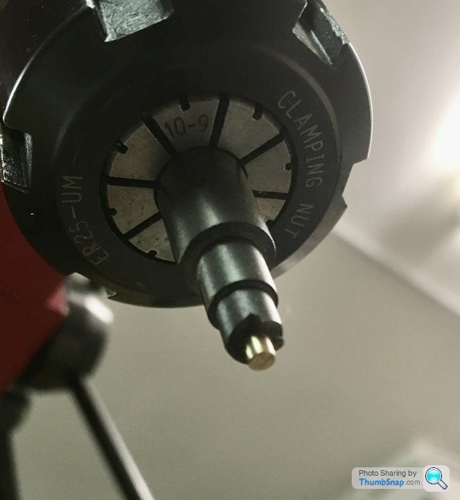
Trouble is, I need to make the cuts to the same length towards the Chuck, and I have no limit stop. I spent most of yesterday’s hobby time making one that screws to the headstock on the lathe. It’s mode of scrap aluminium and some 304 stainless rod. I found a spare quick-release toggle, so decided to use that as a clamp, rather than threading the bar. I did add a cap head screw and lock nut to the end for fine adjustment though. It took a long time to make, mainly because I made it up as I went. I should have drawn it all out, but sometimes that’s the way it happens:
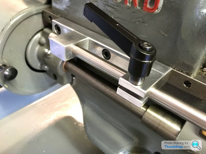


One lesson learned was that accurate alignment in every axis is critical for for consistent chamfering...next time I’ll get it better.
Now for the sprung centering rod...
Trouble is, I need to make the cuts to the same length towards the Chuck, and I have no limit stop. I spent most of yesterday’s hobby time making one that screws to the headstock on the lathe. It’s mode of scrap aluminium and some 304 stainless rod. I found a spare quick-release toggle, so decided to use that as a clamp, rather than threading the bar. I did add a cap head screw and lock nut to the end for fine adjustment though. It took a long time to make, mainly because I made it up as I went. I should have drawn it all out, but sometimes that’s the way it happens:
One lesson learned was that accurate alignment in every axis is critical for for consistent chamfering...next time I’ll get it better.
Now for the sprung centering rod...
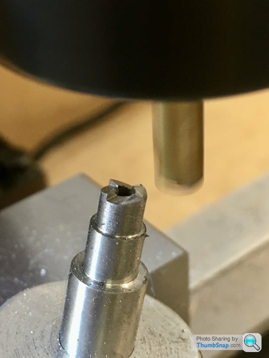
Cracked on with making a centering rod. I made it out of the remains of the 10mm silver steel I got for the spot-face tool, some brass off-cut and a random spring.


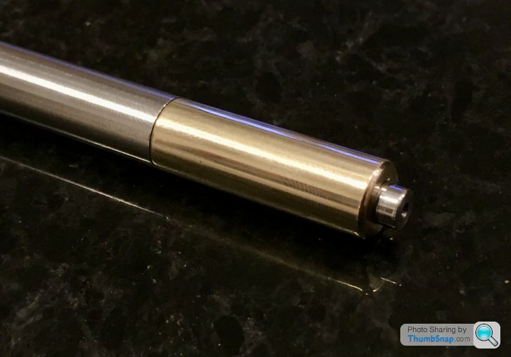

I 3D modelled this time so it only took a couple of hours to make. There is no play in the plunger so hopefully it might work. Not sure about the cone angles, but I suppose I’ll see if it works soon enough on the main bearings...
I 3D modelled this time so it only took a couple of hours to make. There is no play in the plunger so hopefully it might work. Not sure about the cone angles, but I suppose I’ll see if it works soon enough on the main bearings...
Ayahuasca said:
A reciprocating engine?
I have a 1950’s Boys Book of Model Making that includes a chapter and plans for building one of those from scratch. I think boys were more advanced back then.
Pretty much any engine with a piston and crankshaft is a reciprocting engine!I have a 1950’s Boys Book of Model Making that includes a chapter and plans for building one of those from scratch. I think boys were more advanced back then.
There are much simpler steam engines called oscillating engines, which don't have moving valves and eccentric cams etc; the rocking motion of a pivoted cylinder opens and closes steam ports. Mamod engines usually used them, and they are relatively straightforward to make without access to machine tools.
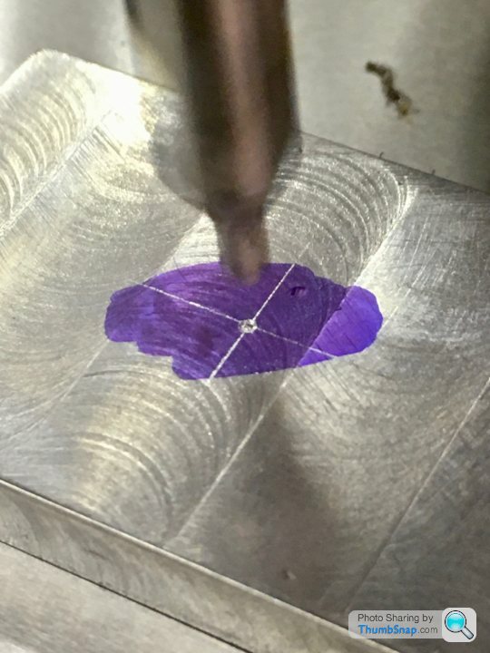
Marked out the centre of the bearing with caliper lines scribed on some blue marker. I had to use an eye loupe to get the punch central - my eyesight certainly isn't what it once was:

Next thing is to mount them in the 4 jaw chuck and align them with the centering rod.
Trouble is, the drawing seems to be wrong: It calls for the bearing width to be 7/16" (11.11 mm), but it's not that to start with - it's only about 10.95mm (hence me buying the wrong sized ball-nose mill). It then calls for the bosses that protrude from this to be 27/64" (10.72 mm) in diameter. So that only gives about a 0.12 mm wide step around the boss - totally out of proportion to the drawing; it should be approximately double that. I guess I could use the calculated step width from the drawing, but then that eats into the bearing face area of the bosses.
I wonder if the drawing is wrong, or they've changed the dimensions of their brass castings?
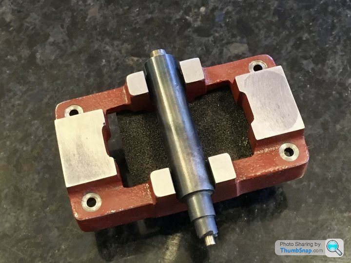
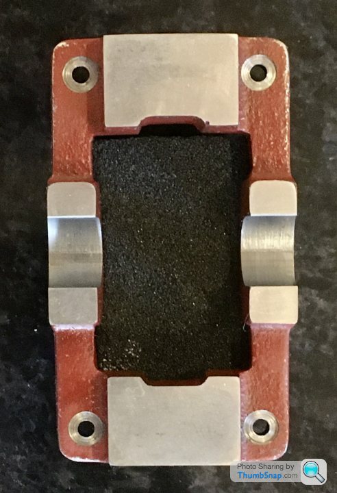
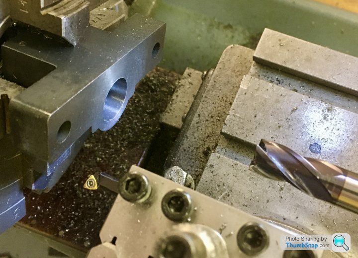
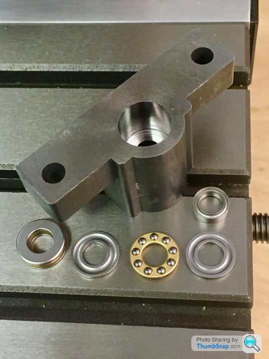
Got distracted with some modifications to the mill - I got some thrust bearings and ball races for the x & y hand wheels. As standard they have plain bushes, and metal to metal face contact on the leadscrew ends. The stiction and feel isn’t nice.
So I removed the hand wheel blocks, mounted them in a 4 jaw chuck and milled/bored the bearing pockets. I used my home made centering bar to align the block - I could get it to about 0.00075” but no better for some reason.
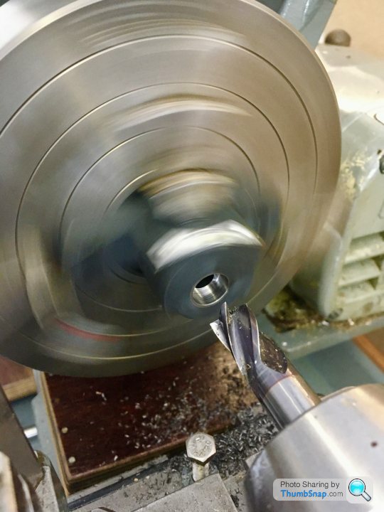
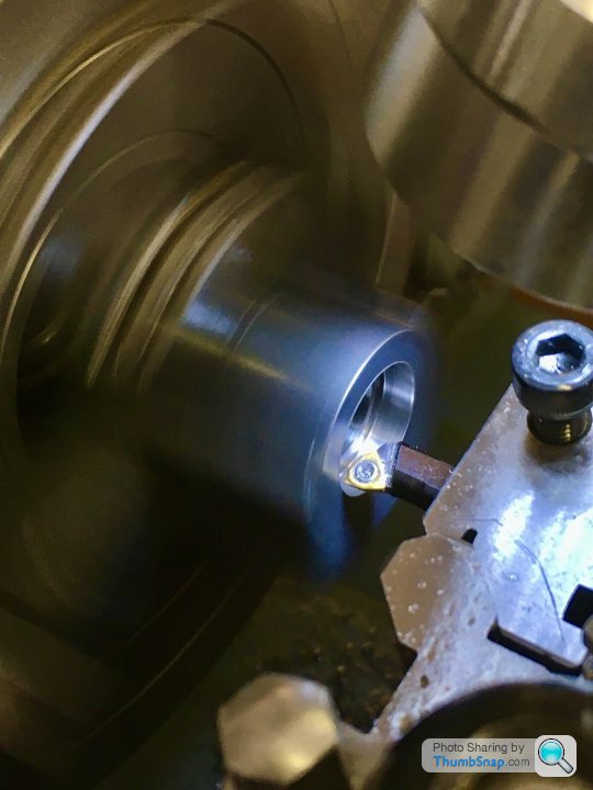
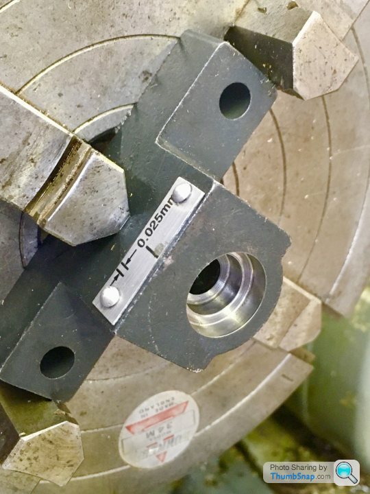
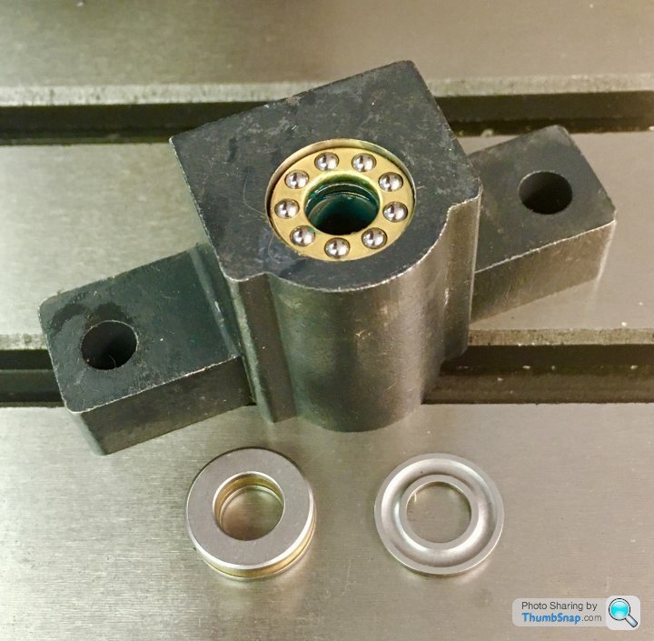
Once re-assembled backlash was reduced by about 30%, just by being able to fully tighten the hand wheel nut. The biggest difference is in feel - night and day improvement with no noticeable stiction.
Very happy with that little exercise, especially as it’s the first time I’ve used a 4 jaw chuck. Next the y-axis, then back to motorise the x-axis so I can get more consistent surface finishes.
So I removed the hand wheel blocks, mounted them in a 4 jaw chuck and milled/bored the bearing pockets. I used my home made centering bar to align the block - I could get it to about 0.00075” but no better for some reason.
Once re-assembled backlash was reduced by about 30%, just by being able to fully tighten the hand wheel nut. The biggest difference is in feel - night and day improvement with no noticeable stiction.
Very happy with that little exercise, especially as it’s the first time I’ve used a 4 jaw chuck. Next the y-axis, then back to motorise the x-axis so I can get more consistent surface finishes.
Gassing Station | Scale Models | Top of Page | What's New | My Stuff