Stuart 10V Vertical Steam Engine
Discussion


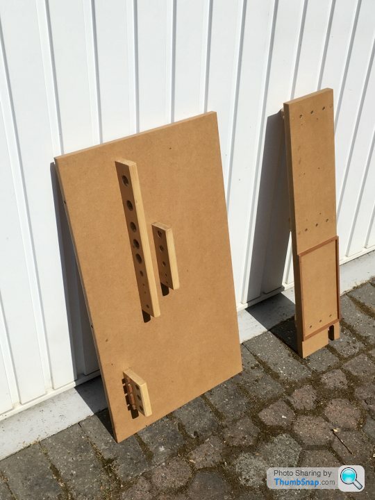
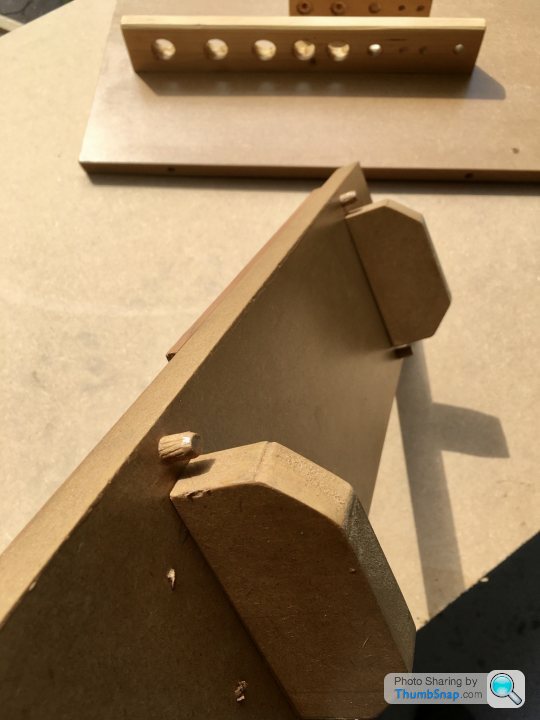
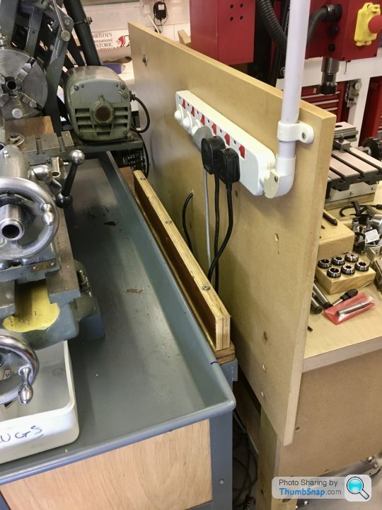
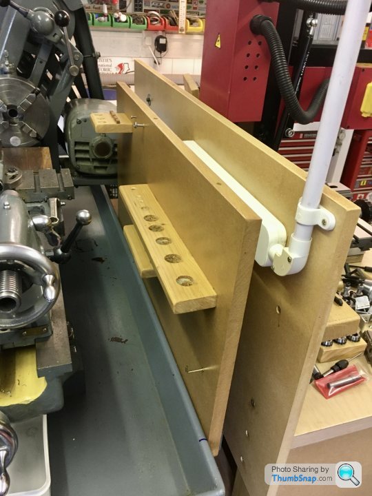
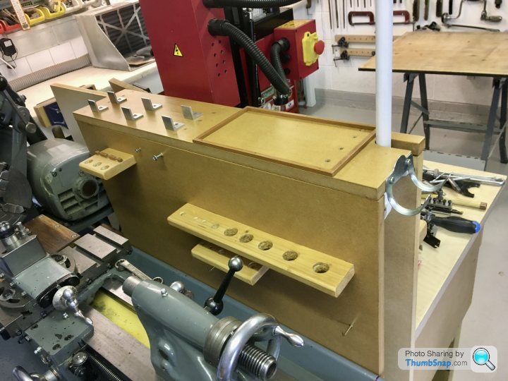
I sacrificed a day on the 10V to make a tool board/shelf for the lathe and milling machines. I was wasting loads of time looking in my tool chest drawers for things. I’ve made it all slot together so I can quickly separate the two benches if I need to move them. Common tools like the collets and soft hammer are in the middle. I cut some aluminium angle up to put the lathe tool holders on.
[url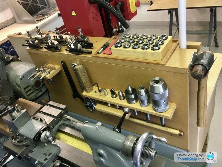 |https://thumbsnap.com/oNw6VGNc[/url]
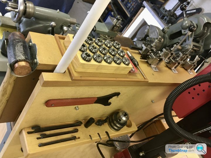
Quite pleased with that, especially since it was made out of scrap MDF so didnt cost anything.
[url
|https://thumbsnap.com/oNw6VGNc[/url]Quite pleased with that, especially since it was made out of scrap MDF so didnt cost anything.
So back to some machining - the main bearings.
I opted to go a bit off-piste, ignore the plan dimensions and mark the center of the cast semi-circle. My reasoning being that at the end of the day, if the turned bosses are not concentric with it, it’ll look wrong, and the specified dimensions are so close anyway, it won’t make any difference to the function of the engine.
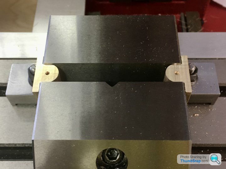
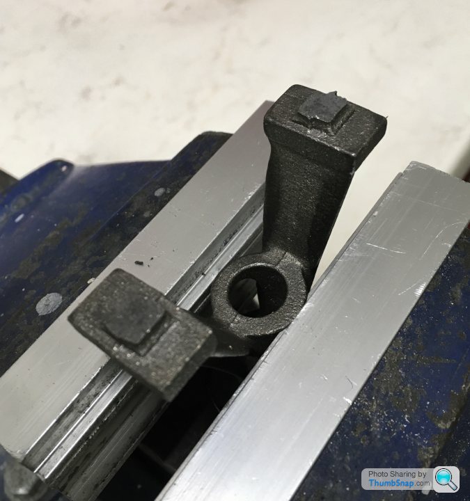
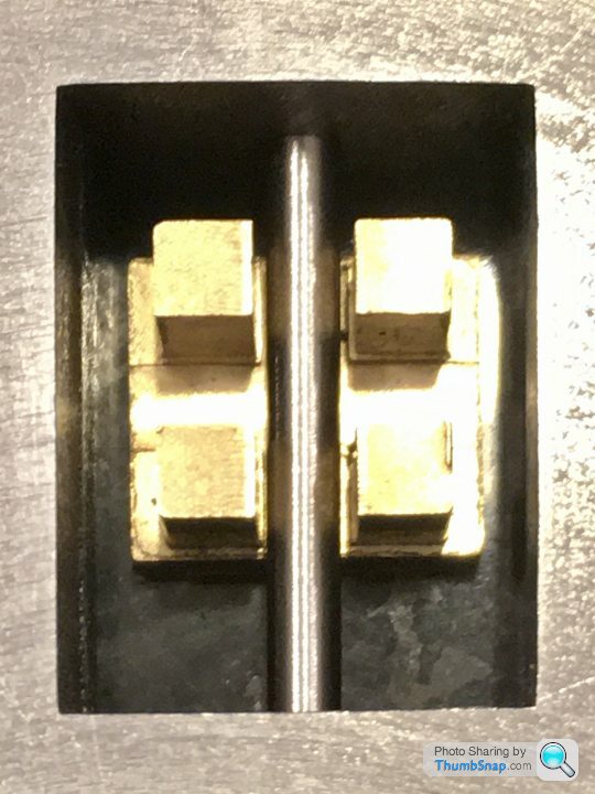
My edge finder is 6mm diameter, so a fraction too large to take a direct measurement from the straight sides of the bosses. I decided to clamp both castings as shown, and calculate the centreline from the inside of the vice faces. Once locked in “y”, It was a simple task to offset from the exposed curved surfaces, and center drill them:
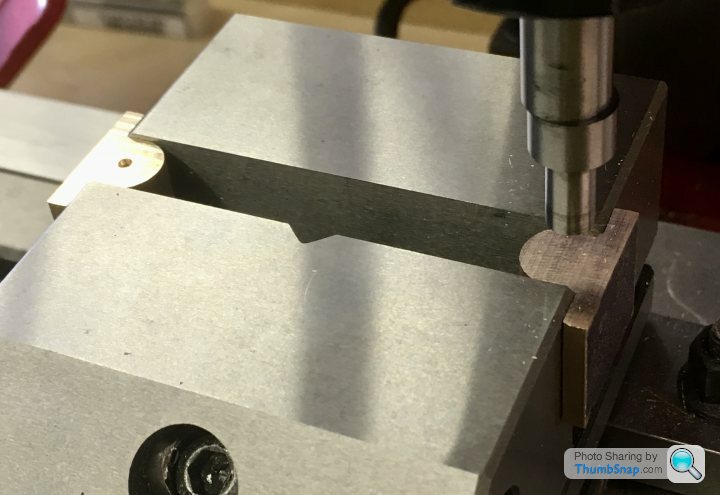
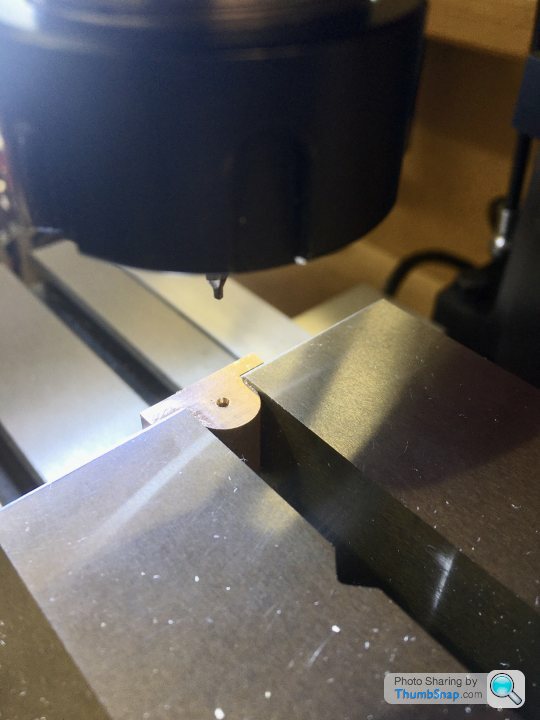
No idea if that’s a good way of doing it, but it made sense to me and it seemed to work.
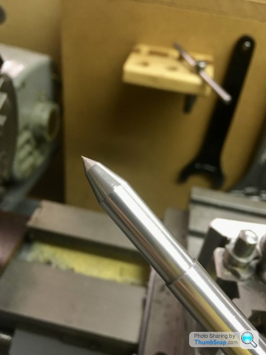
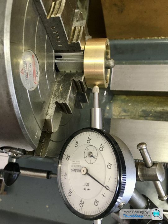
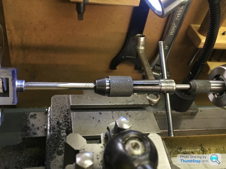
Then onto the lathe to drill the crankshaft holes. I spent a good 45 minutes faffing about with shims in the 3 jaw chuck, and getting nowhere near true. In the end I cut some square spacers and used the 4 jaw chuck, and it was centred to less than 0.001” within a couple of minutes. I locally re-profiled my centering bar tip to 60 degrees included, and it seems OK now. Still needs holding to prevent rotation though:

I drilled them progressively up to 6.8mm. My plan is to line drill both bearings in-situ to 6.9mm, then ream in the same setup.
Wall thickness around the curved area is within about 0.004”. I doubt I could currently get any better, so that’s that.
Next up: make a mandrel and cut the bosses on the lathe.
I opted to go a bit off-piste, ignore the plan dimensions and mark the center of the cast semi-circle. My reasoning being that at the end of the day, if the turned bosses are not concentric with it, it’ll look wrong, and the specified dimensions are so close anyway, it won’t make any difference to the function of the engine.
My edge finder is 6mm diameter, so a fraction too large to take a direct measurement from the straight sides of the bosses. I decided to clamp both castings as shown, and calculate the centreline from the inside of the vice faces. Once locked in “y”, It was a simple task to offset from the exposed curved surfaces, and center drill them:
No idea if that’s a good way of doing it, but it made sense to me and it seemed to work.
Then onto the lathe to drill the crankshaft holes. I spent a good 45 minutes faffing about with shims in the 3 jaw chuck, and getting nowhere near true. In the end I cut some square spacers and used the 4 jaw chuck, and it was centred to less than 0.001” within a couple of minutes. I locally re-profiled my centering bar tip to 60 degrees included, and it seems OK now. Still needs holding to prevent rotation though:
I drilled them progressively up to 6.8mm. My plan is to line drill both bearings in-situ to 6.9mm, then ream in the same setup.
Wall thickness around the curved area is within about 0.004”. I doubt I could currently get any better, so that’s that.
Next up: make a mandrel and cut the bosses on the lathe.
Edited by dr_gn on Monday 1st June 23:37
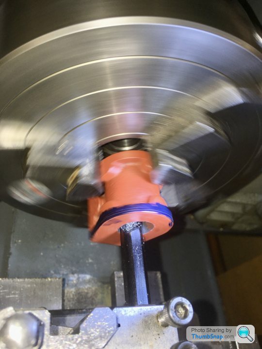
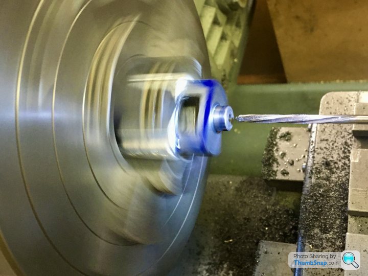
Turned a bearing mandrel from some scrap brass rod, and threaded the end M5:

I made a spacer for the end, to the correct boss diameter, so I could easily see when I was nearly at the right size:

Marked up and cut:

I’ve never tried intermittent cuts on the lathe before, but it was fine.

I’ve polished to top surfaces with wet and dry on the surface plate, ready for drilling. Shame there are some surface flaws I can’t get rid of.
I left all the bosses long, so I could size them precisely to the crank webs and eccentric. Not sure how I’ll hold them for that - perhaps in the collet chuck, or modify my mandrel somehow.
I made a spacer for the end, to the correct boss diameter, so I could easily see when I was nearly at the right size:
Marked up and cut:
I’ve never tried intermittent cuts on the lathe before, but it was fine.
I’ve polished to top surfaces with wet and dry on the surface plate, ready for drilling. Shame there are some surface flaws I can’t get rid of.
I left all the bosses long, so I could size them precisely to the crank webs and eccentric. Not sure how I’ll hold them for that - perhaps in the collet chuck, or modify my mandrel somehow.
henryk001 said:
Nice work, just a thought. Is your model going to a static display model or a working one?. If its going to run can i suggest that it would be wise to bore a small groove, just a few thou at both ends of the brass bearing inset from the edge and a groove top and bottom along the bore to only meet the end grooves creating a lubrication gallary and finally a small hole drilled to allow lubrication of the shaft. Its what we had to do on maintenance years ago when we replaced worn brass crankshaft bearings in a press.
The grooves allowed for lubrication of the crankshaft and the ring grooves minimised the amount of leakeage. Trust this helps
Thanks Henry - I'm building it to run, but it's not like it'll be every day! The next job on the bearings is to drill them for the mounting holes, and a central through-hole for lubrication. This lubrication hole is specified on the drawings. I'll get the optional oilers for the bearings to screw into the lubrication holes. I think the bearings will have enough clearance to distribute the oil without grooves - especially with my current level of machining skill! I think it will get tested on compressed air, and then I'll maybe buy a Wilesco boiler to run it on at some point. I'd like to build the Stuart Twin Victoria, Major Beam and Triple Expansion engines too, so I'll have to think of some way of generating steam.The grooves allowed for lubrication of the crankshaft and the ring grooves minimised the amount of leakeage. Trust this helps
Cheers!
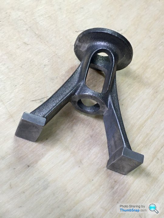
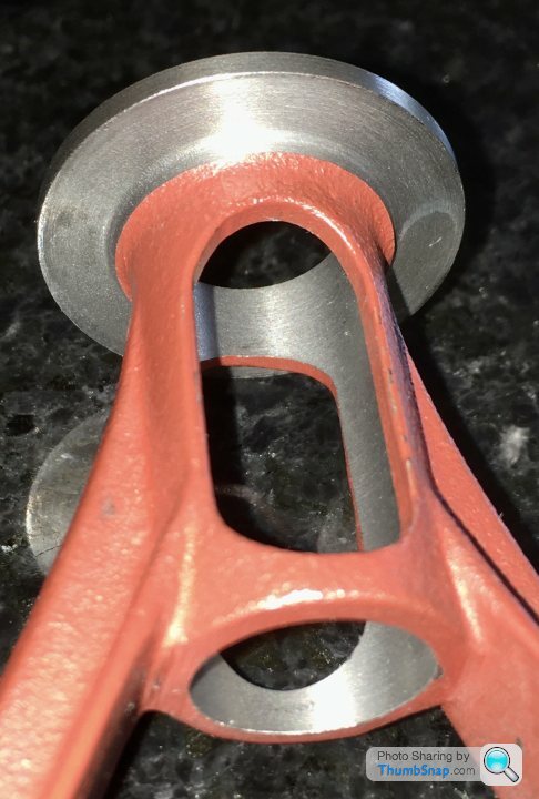
Moved on to the standard - I’ll do all the base drilling at the same time.
First job- clean up the castings with files:
I made a mandrel from a cut down bolt, cross-drilled for a drive screw:

I wrapped some shim steel just to take up the bit of play, and copper washers to protect the collet and casting:
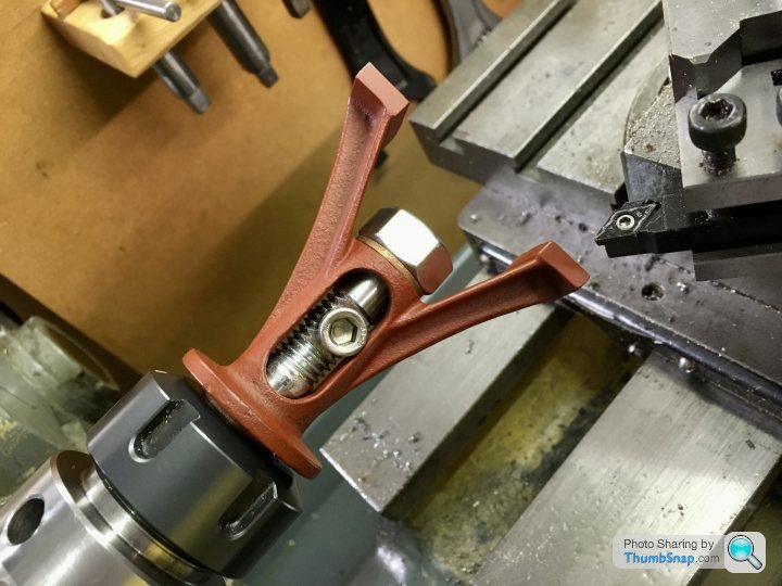
I should have let the bolt protrude more so I had room for a tail support, but in practice it machined easily:
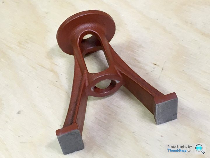
I might have to machine some more off the feet, because when I marked the specified height with a scriber, it seemed too far down the upper flange. If I machine down to that, getting the thickness right won’t be possible:
Then again by the time I’m done cleaning the top face up, getting the specified thickness will be very close I think. I’m wondering whether to just leave the feet, clean up the underside of the flange and see where I am. Maybe live with the overall height being a millimetre or so too much. Not sure - seems like a bit of a bodge.
First job- clean up the castings with files:
I made a mandrel from a cut down bolt, cross-drilled for a drive screw:
I wrapped some shim steel just to take up the bit of play, and copper washers to protect the collet and casting:
I should have let the bolt protrude more so I had room for a tail support, but in practice it machined easily:
I might have to machine some more off the feet, because when I marked the specified height with a scriber, it seemed too far down the upper flange. If I machine down to that, getting the thickness right won’t be possible:
Then again by the time I’m done cleaning the top face up, getting the specified thickness will be very close I think. I’m wondering whether to just leave the feet, clean up the underside of the flange and see where I am. Maybe live with the overall height being a millimetre or so too much. Not sure - seems like a bit of a bodge.
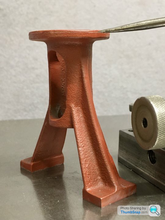
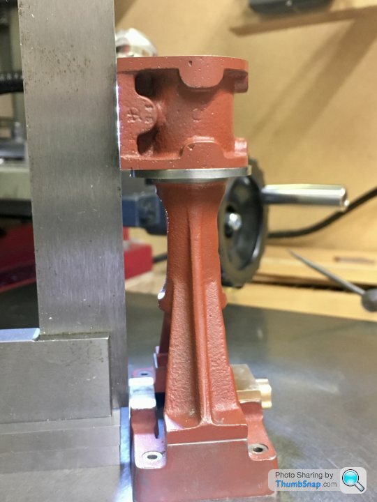
I took a bit more off the feet, and then prepared the casting for fitting to the faceplate by hammering a dowel plug Into the end, and marking the centre using callipers. I modded my vice clamps and used them to secure. It was easy to align everything to a centre in the tailstock:
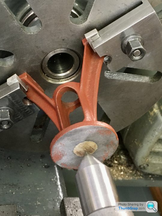
Then used right and left handed tools to machine the top, edge and bottom surfaces. I had some resistance around the o/d of the top plate, presumably due to chill hardening of the casting again:

Then on to the bore, using the same setup to keep everything square. Used my large Sandvik boring bar, and a new insert. Tore through it no problem:
So that was that:
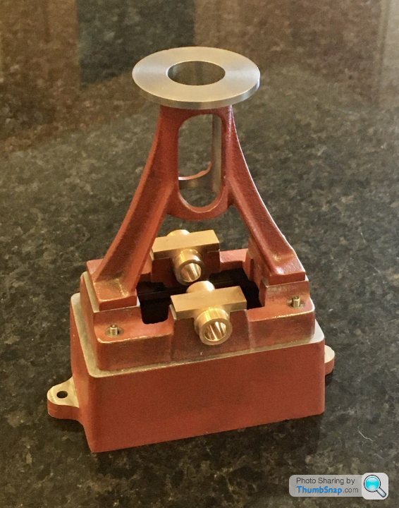
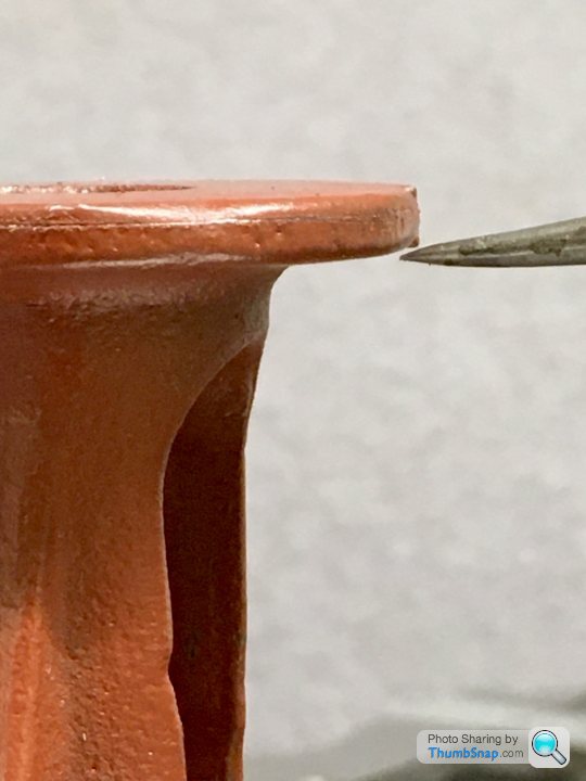
When all’s said and done, according to the drawings, overall height is about 0.025” too tall, bore diameter about 0.002” too big. Flange diameter and thickness pretty much spot on. I think I maybe should have gone further in with the flange underside machining because the nuts are going to be very close to the cast side. It was difficult to judge, but not the end of the world to correct if it’s an issue. There is a slight flaw in the flange edge that wouldn’t clean up, but it’s not too bad.
First time I’ve used a faceplate, so fairly pleased with the result.
Then used right and left handed tools to machine the top, edge and bottom surfaces. I had some resistance around the o/d of the top plate, presumably due to chill hardening of the casting again:
Then on to the bore, using the same setup to keep everything square. Used my large Sandvik boring bar, and a new insert. Tore through it no problem:
So that was that:
When all’s said and done, according to the drawings, overall height is about 0.025” too tall, bore diameter about 0.002” too big. Flange diameter and thickness pretty much spot on. I think I maybe should have gone further in with the flange underside machining because the nuts are going to be very close to the cast side. It was difficult to judge, but not the end of the world to correct if it’s an issue. There is a slight flaw in the flange edge that wouldn’t clean up, but it’s not too bad.
First time I’ve used a faceplate, so fairly pleased with the result.
Edited by dr_gn on Friday 5th June 17:52
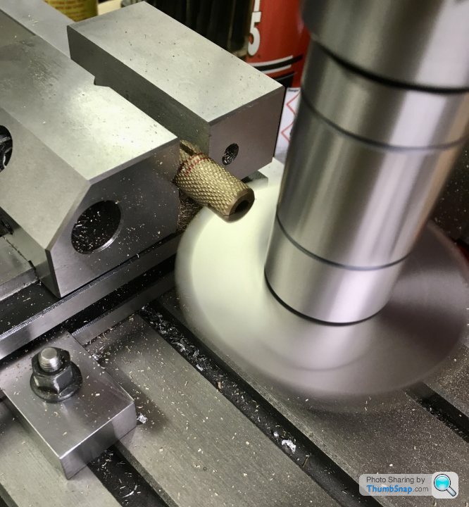
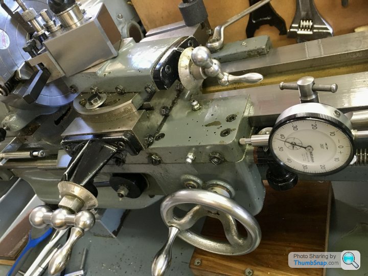
Got a bit distracted again, this time adding a motor to the x-feed screw. I found a ‘how to’ online, and half followed it. First job was to extend the lead screw and cross-drill it for a drive pin:

A simple dog clutch is made from a pice of brass, turned, knurled and slotted at both ends with a “what could possibly go wrong?” slitting saw:
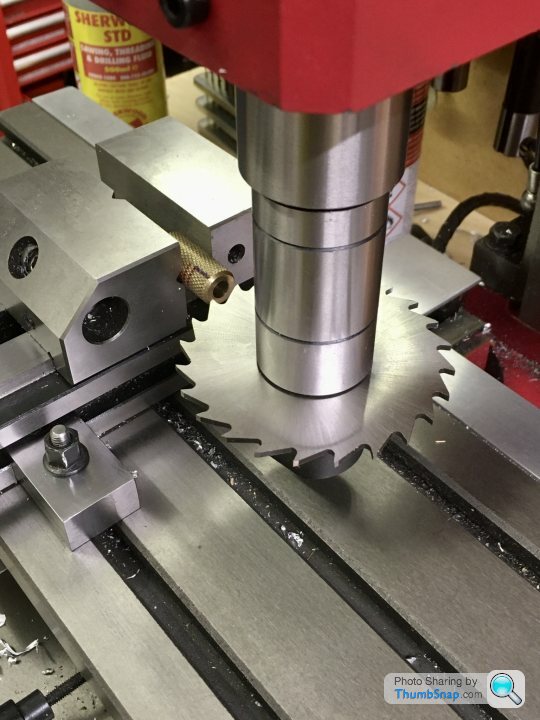
Then drill and tap the end of the bed to take some bolts and spacers for a motor plate:
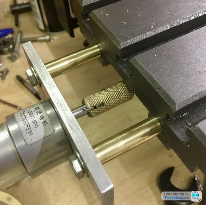
It’s a 12v geared motor. I’ll be running it through a 15v PWM speed controller. Obviously still needs a casing and control panel, but it seems to work ok on a 12v battery charger.
A simple dog clutch is made from a pice of brass, turned, knurled and slotted at both ends with a “what could possibly go wrong?” slitting saw:
Then drill and tap the end of the bed to take some bolts and spacers for a motor plate:
It’s a 12v geared motor. I’ll be running it through a 15v PWM speed controller. Obviously still needs a casing and control panel, but it seems to work ok on a 12v battery charger.
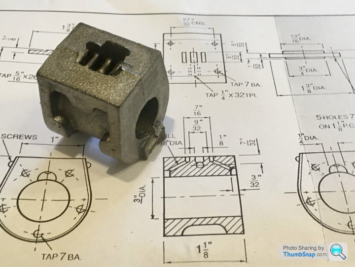
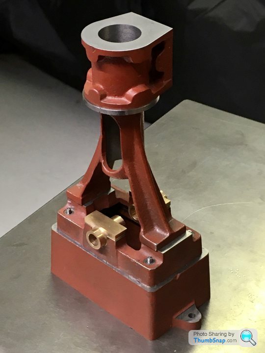
So on to one of the critical bits: the cylinder. The black casting is a bit rough:
The drawings have the minimum information, un-toleranced (luckily):
Started by cleaning up the outside by filing:
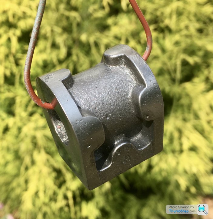
And painted with red oxide so I can see what’s what.
After looking at online builds and my 10V book, it seems like there are many ways to machine this part. I went with what I understood, and what I thought was easiest. I’m not sure it’s worked out, but more on that later. I scribed my best fit line around one end from the surface, using callipers. Then did a quick check to see if everything was about the right height all around:
Double checked with it in the chuck. I put a parallel behind it to make it as square as a filed casting face would allow:
Then clocked it up to the best fit around the cast circular flange. I did this rather than the bore because there needs to be a constant depth step around here for the insulation plate, defined by the cylinder caps:
And checked the filed face was about right:
Bored the...bore:
Faced:

Then removed and marked out using callipers for the length. I also scribed “B” on the casting so I know this is the lower end and everything is perpendicular (hopefully):
Re-fitted in the chuck using a parallel to seat the machine face on:
I thought about the next operation a lot, but it seemed like alignment by eye was as good as anything. I calculated the bore-face dimension using my bore size, and calculated how much to remove from the cast/filed face. I then scribed a line from the face using callipers. I put the cylinder in the vice and eyeballed the level using a parallel and slip gauge to form a datum plane. This was done both sides as a check, and it seemed to match:
I used the parallel/gauge to set the fly cutter to zero on the DRO for depth:
Then fly cut the face using my new x-axis power feed:
I’m happy with the finish:

I balanced everything together and it seems to be square:

However, despite the cast flanges being equal depth to within about 0.15mm (the book advises to aim to get these the same), the port-face distances aren’t equal, there being about a 0.5mm discrepancy:
I think I can compensate for this error by adjusting the slide valve on its rod.
Also, the faces aren’t parallel. I’ve got an approx. 0.17mm difference front/back. This must have been due to me using the chuck face/parallel as a datum somehow. Perhaps I should have made a mandrel. I don’t think it will really matter so long as the first (bottom) face is normal to the bore axis, but it is annoying to get it so wrong.
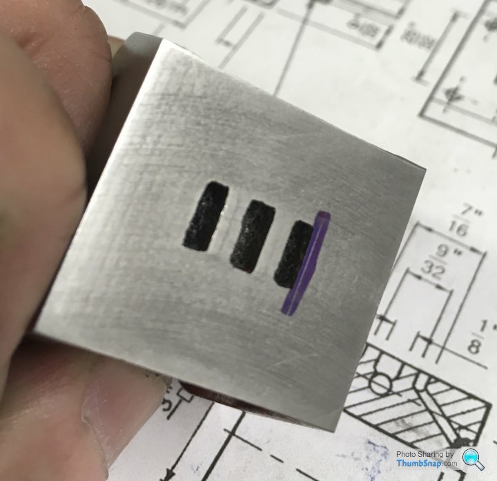
Next job: steam ports.
The drawings have the minimum information, un-toleranced (luckily):
Started by cleaning up the outside by filing:
And painted with red oxide so I can see what’s what.
After looking at online builds and my 10V book, it seems like there are many ways to machine this part. I went with what I understood, and what I thought was easiest. I’m not sure it’s worked out, but more on that later. I scribed my best fit line around one end from the surface, using callipers. Then did a quick check to see if everything was about the right height all around:
Double checked with it in the chuck. I put a parallel behind it to make it as square as a filed casting face would allow:
Then clocked it up to the best fit around the cast circular flange. I did this rather than the bore because there needs to be a constant depth step around here for the insulation plate, defined by the cylinder caps:
And checked the filed face was about right:
Bored the...bore:
Faced:
Then removed and marked out using callipers for the length. I also scribed “B” on the casting so I know this is the lower end and everything is perpendicular (hopefully):
Re-fitted in the chuck using a parallel to seat the machine face on:
I thought about the next operation a lot, but it seemed like alignment by eye was as good as anything. I calculated the bore-face dimension using my bore size, and calculated how much to remove from the cast/filed face. I then scribed a line from the face using callipers. I put the cylinder in the vice and eyeballed the level using a parallel and slip gauge to form a datum plane. This was done both sides as a check, and it seemed to match:
I used the parallel/gauge to set the fly cutter to zero on the DRO for depth:
Then fly cut the face using my new x-axis power feed:
I’m happy with the finish:
I balanced everything together and it seems to be square:
However, despite the cast flanges being equal depth to within about 0.15mm (the book advises to aim to get these the same), the port-face distances aren’t equal, there being about a 0.5mm discrepancy:
I think I can compensate for this error by adjusting the slide valve on its rod.
Also, the faces aren’t parallel. I’ve got an approx. 0.17mm difference front/back. This must have been due to me using the chuck face/parallel as a datum somehow. Perhaps I should have made a mandrel. I don’t think it will really matter so long as the first (bottom) face is normal to the bore axis, but it is annoying to get it so wrong.
Next job: steam ports.
fourfoldroot said:
Do you always hammer (with a soft hammer) the work into the chuck/ mill vice as you tighten? If not the work can tilt a little, enough to produce a 0.17 discrepancy. Also, I tend to leave the parallels in whilst machining to stop movement. On the lathe that may mean zip tying them so they don't fly off , and standing out of line. Anyway it's all looking good so far, it's going to be the best 10V build ever!
Thanks, yes I tapped the parallel. There was only room for one, and I had to remove it for the boring operation. For the other face Ileft it in, becasue obviously the bore was done by then. That's probably where it went a bit wrong, although I did check the filed face before machining and it was only a few thou out, and that was probably the surface roughness.Still, so long as the bore is normal to the bottom face it doesn't really matter I guess?
fourfoldroot said:
No, it won’t matter. As you say, the bore being perpendicular to the bottom face is the critical part. You can always dome the cylinder cover in case anyone is tempted to put a miniature precision spirit level on it ! 
You are getting close to doing the bits I found hardest, the crankshaft and drilling the valve rod guide into the domed end of the steam chest.
I've not really figured out the valve gear yet - or at least the fit required. You are getting close to doing the bits I found hardest, the crankshaft and drilling the valve rod guide into the domed end of the steam chest.
I assume the valve slider needs to be a very good sliding fit between the valve face and cover, otherwise it won't seal? Or at least the square plate that moves the slider needs to press the slider against the port faces? The chest has gaskets, so I'm not sure how I'll get that fit apart from trial and error test assembly.
fourfoldroot said:
Port face needs to be nice and smooth,as does the slide valve face. However it floats and is held against port face by steam pressure. The valve operating block is not a tight fit and the slide valve prongs don’t rub on the valve chest cover, which all makes life easier.
Of course - the valve box is always at a higher pressure than the exhaust port. I was getting a bit fidgety about lapping things between gasketed parts...Thanks.BTW fly cutting with the power feed gave a great finish, but I also lapped the port face with 1200 wet and dry lubed with WD40 on my surface plate. I'll finish it with Autosol on some thin cloth. I'll do the same with the slider face. Should easily get a gas-tight sliding seal.
Strange thing is, the brass slider is already fully machined (including the pocket) from brass. I wonder why they did that?
fourfoldroot said:
I think the brass slider/valve is a pressing rather than a casting, so much cleaner finish. As you say,all you need to do is flat the face. You may need to fettle the prongs where the valve rod block slots in. But nothing machiney.
Mine’s fully machined. Maybe they ran out of forgings?Had a spare hour and a half, so started on the valve chest, while the dimensions of the cylinder port face and lagging were still fresh in my mind:
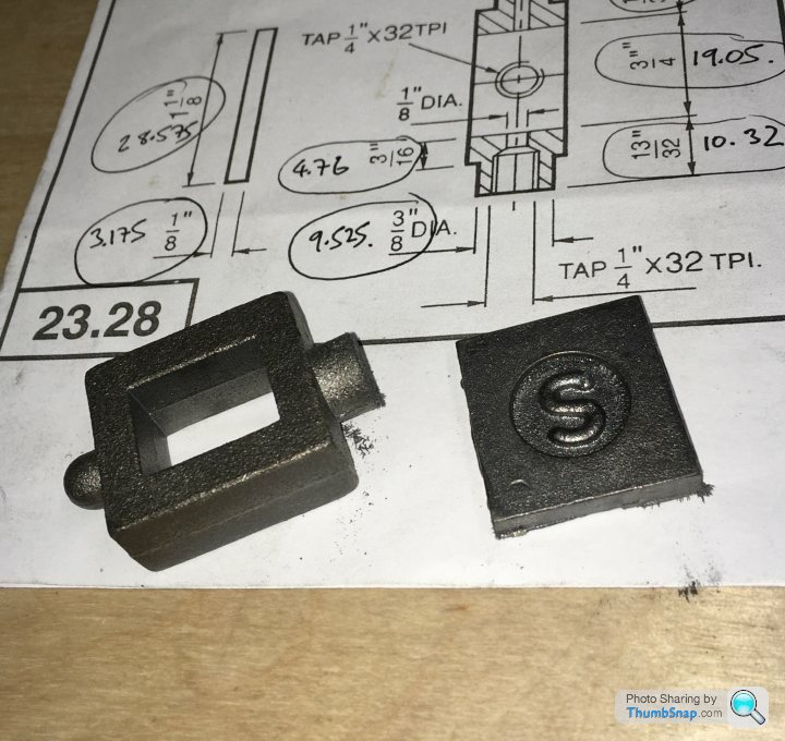
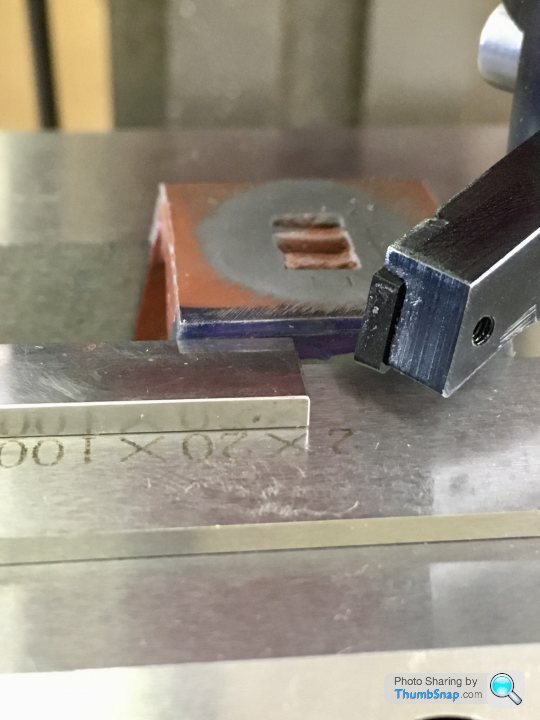
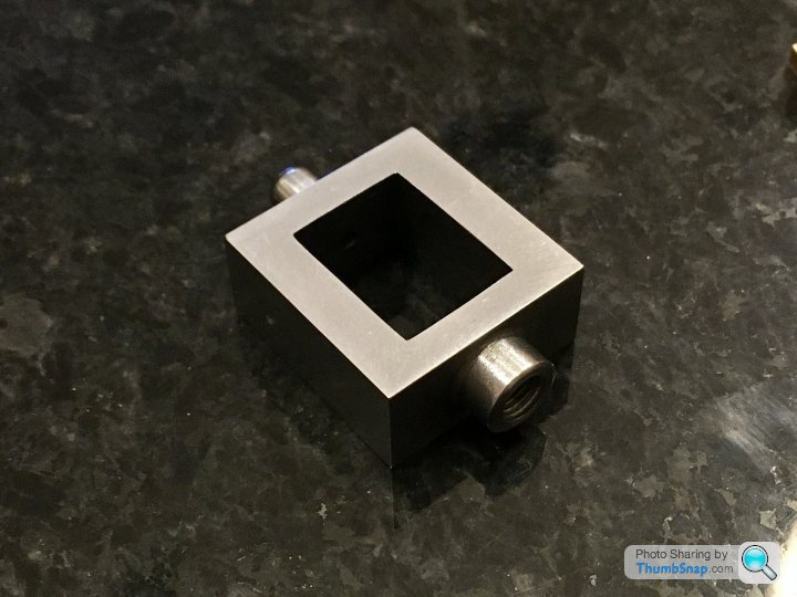
I tried the approach of cleaning up the outer surfaces, measuring, and re-cutting to size using the DROs, and with scribed lines as a sanity check:

All faces were square and dimensions were spot-on to the limit of what I can measure, so that’s one method I can hopefully use from now on:
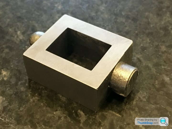
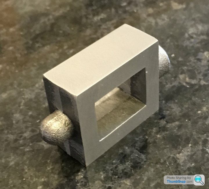
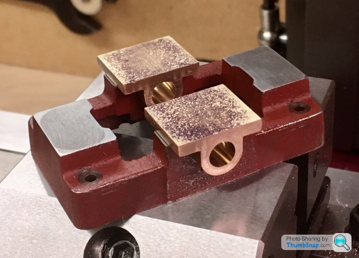
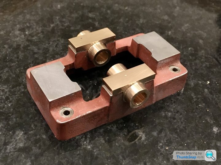
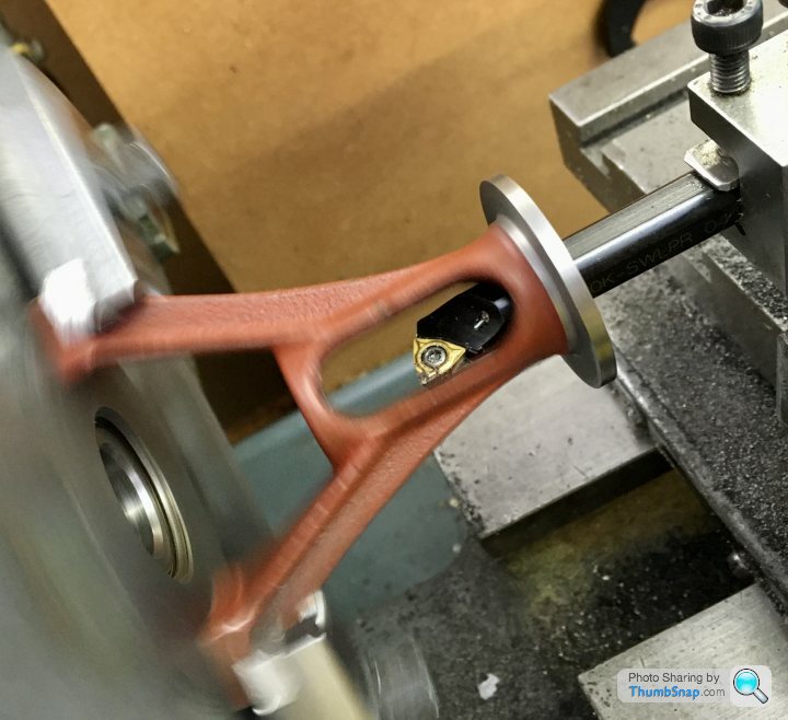
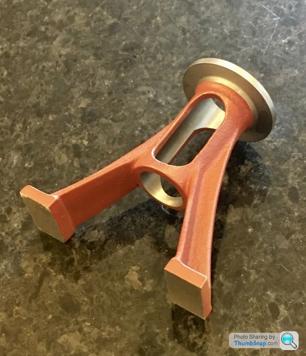
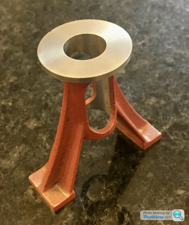
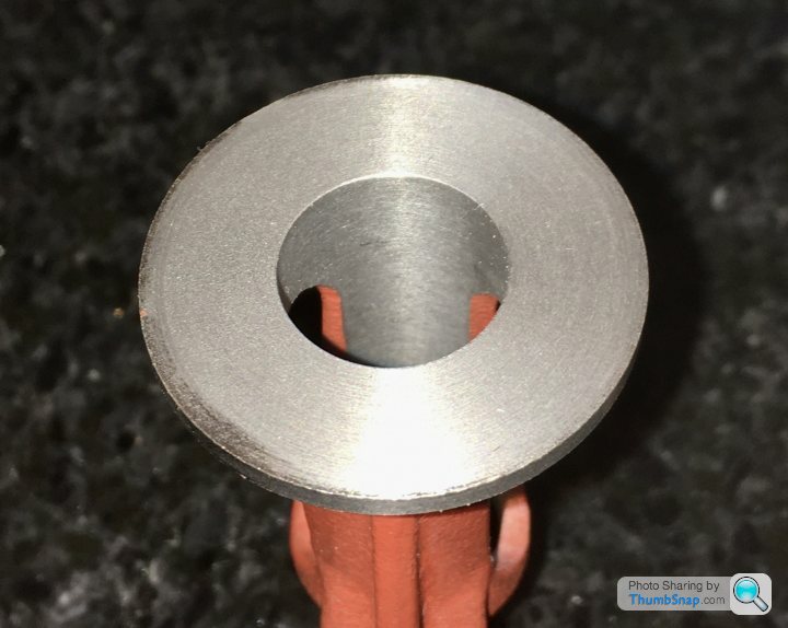
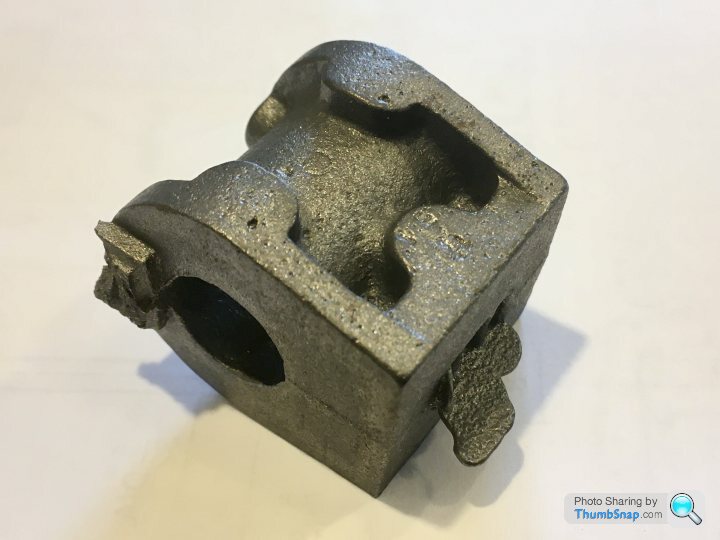
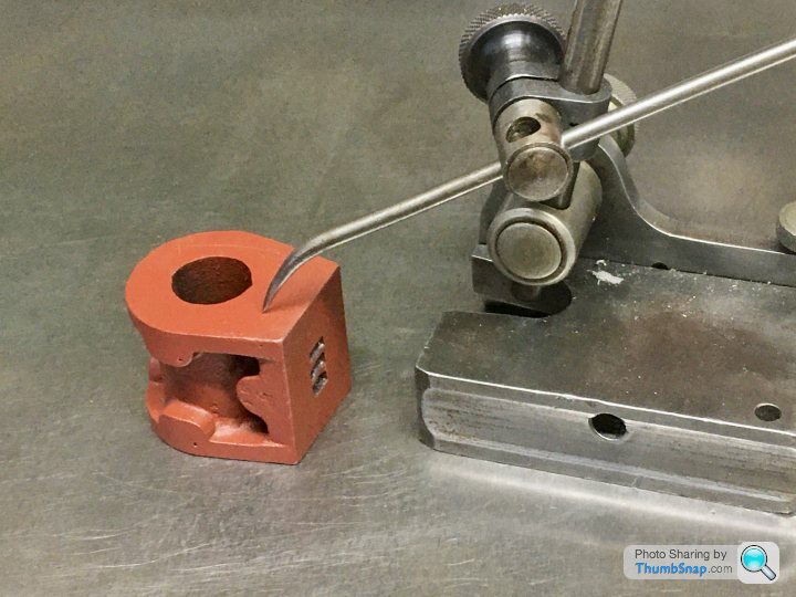
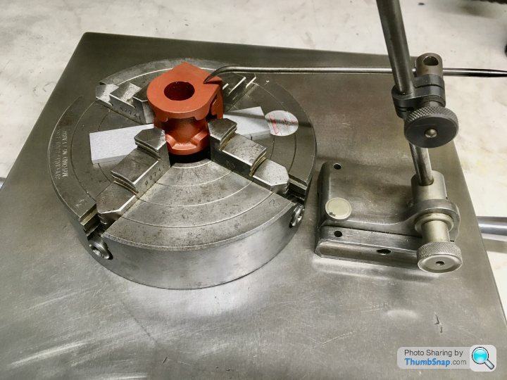
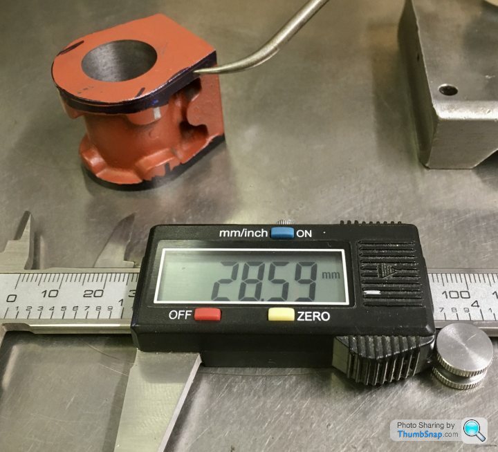
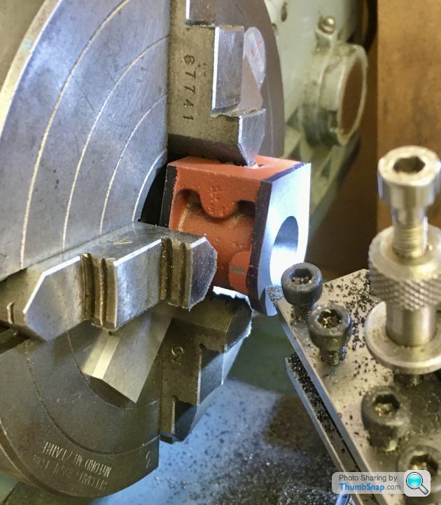
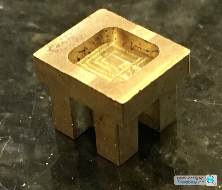
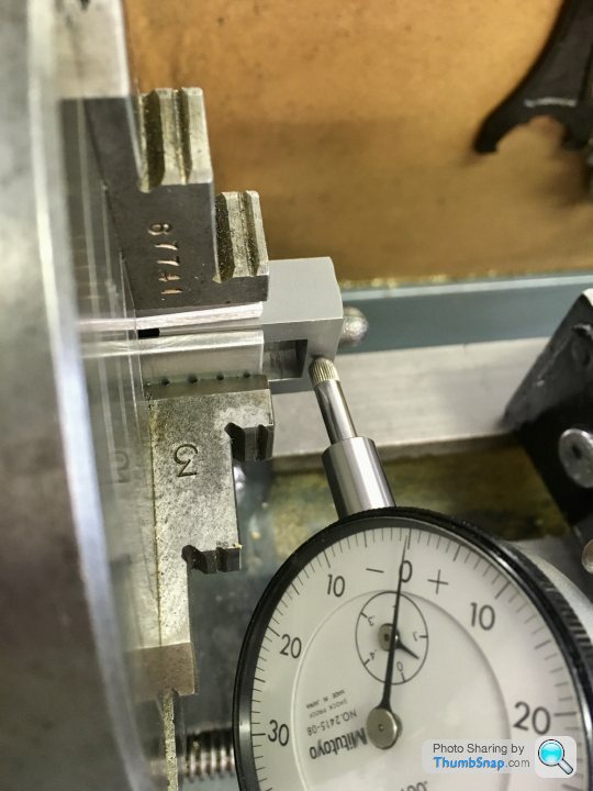
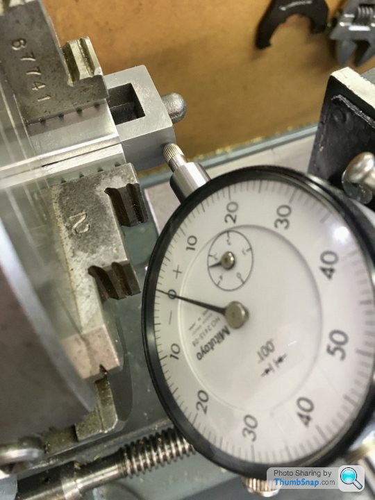
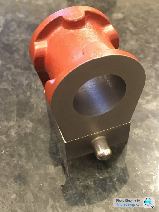
However, this still leaves the bosses to machine. I need to turn these in the 4 jaw chuck, but I couldn’t think how to centralise them accurately. The cast bosses may not now be in the exact mid point of their faces, but they need to be. Anyway I’m going to try this centering ring I made from some scrap brass:

It’s a tight fit over the edges of the chest, and I’ll fit it over the 10mm or so of the part protruding from the jaws. The back face of the ring will butt up to them. If I can center the part using a DTI on the ring, the excess material removed from the bosses should leave me with the finished drilled, tapped and reamed features bang in the middle, and the chuck jaws should ensure they are central within the box:
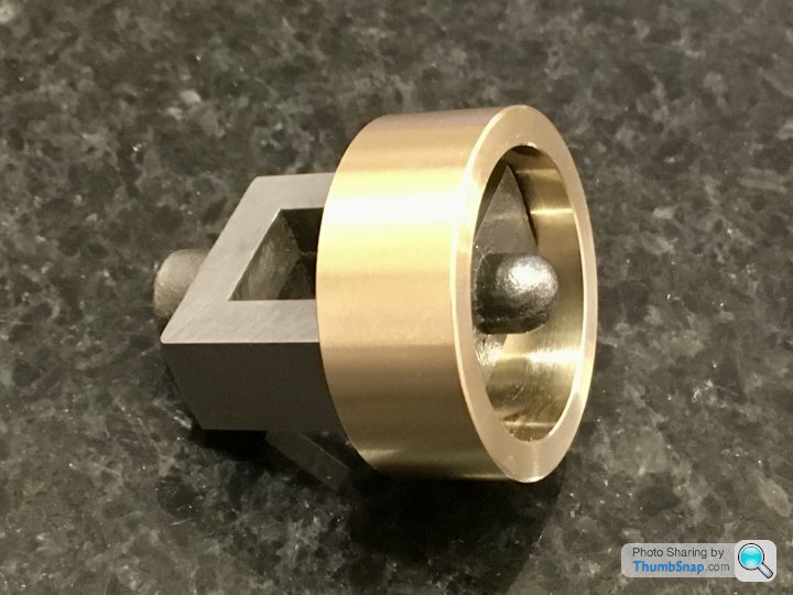
That’s the theory anyway.
I tried the approach of cleaning up the outer surfaces, measuring, and re-cutting to size using the DROs, and with scribed lines as a sanity check:
All faces were square and dimensions were spot-on to the limit of what I can measure, so that’s one method I can hopefully use from now on:
However, this still leaves the bosses to machine. I need to turn these in the 4 jaw chuck, but I couldn’t think how to centralise them accurately. The cast bosses may not now be in the exact mid point of their faces, but they need to be. Anyway I’m going to try this centering ring I made from some scrap brass:
It’s a tight fit over the edges of the chest, and I’ll fit it over the 10mm or so of the part protruding from the jaws. The back face of the ring will butt up to them. If I can center the part using a DTI on the ring, the excess material removed from the bosses should leave me with the finished drilled, tapped and reamed features bang in the middle, and the chuck jaws should ensure they are central within the box:
That’s the theory anyway.
Edited by dr_gn on Monday 15th June 22:20
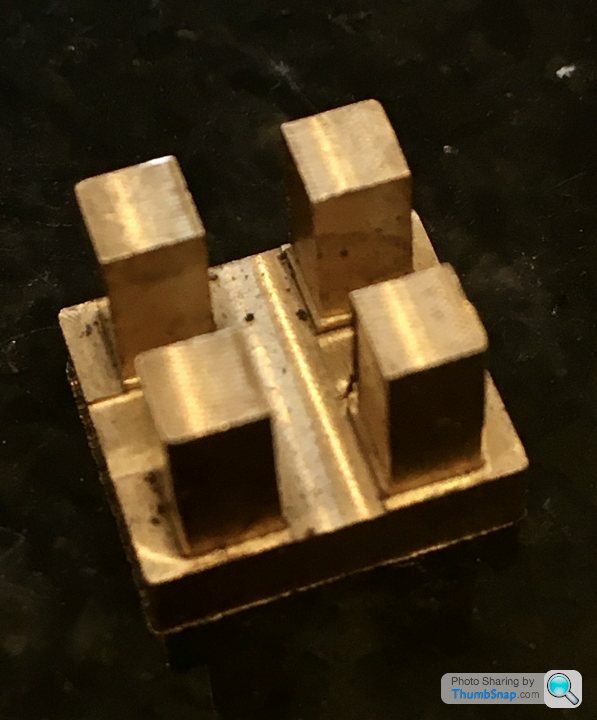
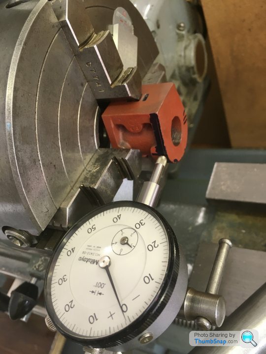
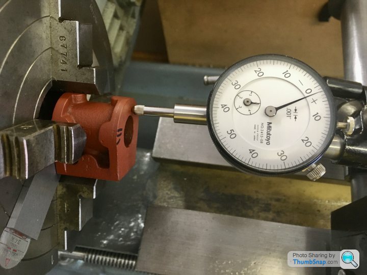
Made some more progress on the valve chest. I used the setting ring, and double checked using the depth to face method. All checked out to well within 0.001”
I set up for facing to a set depth using my end stop and a DTI on the saddle. Then forgot to tighten the tool holder, so it moved during the first cut. Ended up machining to a scribed line. Again.
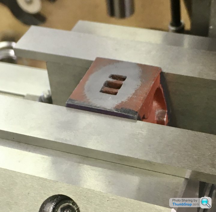
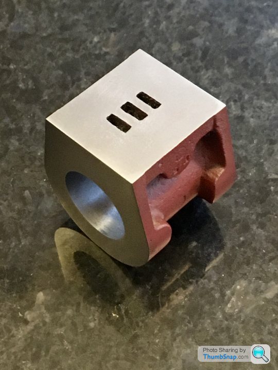
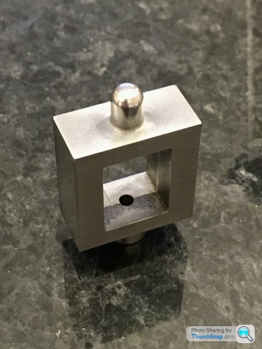
Anyway, turned the part around and drilled, reamed and tapped the valve rod holes in one setup:
The holes seemed to be co-axial, and the 1/8” rod is a nice fit:


Slide valve seems to be central, so that’s OK:
It is a hair too long, purely due to the DTI/tool holder screw up, but it’s not noticeable, nor does it impact any other fit. I added 0.5mm excess to the sides to allow for the Aluminium lagging plate:
A side effect of this is that the cover plate will be fractionally too small once cleaned up:
So long as it’s equal all around I guess it’ll be ok. BTW the domed tip boss was filed to shape while spinning in the chuck:
So now Im wondering about the best way to drill the mounting holes for the valve chest and cover. I don’t want to end up with it on the piss, like it is on the cover of my book. I’m thinking of clamping everything together, and drilling through as a stack.
I set up for facing to a set depth using my end stop and a DTI on the saddle. Then forgot to tighten the tool holder, so it moved during the first cut. Ended up machining to a scribed line. Again.
Anyway, turned the part around and drilled, reamed and tapped the valve rod holes in one setup:
The holes seemed to be co-axial, and the 1/8” rod is a nice fit:
Slide valve seems to be central, so that’s OK:
It is a hair too long, purely due to the DTI/tool holder screw up, but it’s not noticeable, nor does it impact any other fit. I added 0.5mm excess to the sides to allow for the Aluminium lagging plate:
A side effect of this is that the cover plate will be fractionally too small once cleaned up:
So long as it’s equal all around I guess it’ll be ok. BTW the domed tip boss was filed to shape while spinning in the chuck:
So now Im wondering about the best way to drill the mounting holes for the valve chest and cover. I don’t want to end up with it on the piss, like it is on the cover of my book. I’m thinking of clamping everything together, and drilling through as a stack.
fourfoldroot said:
Glue em all together with loctite and then drill, clearance drill cover and chest,careful with depth,then tap cylinder. Disassemble with heat.
Have you drilled domed valve rod guide 1/8th ? If so plans have changed. My problem was 3/32 drills are short so I struggled to drill it through the valve gland (Ooer missus).

No, the hole in the dome has to be smaller than 1/8”, because the 1/8” rod has to be threaded half way down to give an adjustment method for the slider. The top end has to be smaller than the root diameter of that thread in order to get the die down it. I used a Dormer TiN coated 2.4mm drill, not 3/32” (2.38mm). I paid particular attention to cleaning the face so the drill wouldn’t wander. The end of the rod has to be turned to fit the upper hole, so The 0.02mm difference is irrelevant. I don’t really get why the lower end (1/8”) hole needs reaming, yet the top one doesn’t. They both locate the valve rod as a sliding fit. If they didn’t, the upper hole would be redundant.Have you drilled domed valve rod guide 1/8th ? If so plans have changed. My problem was 3/32 drills are short so I struggled to drill it through the valve gland (Ooer missus).
fourfoldroot said:
Yes,good, it’s just from pic with valve and rod in place it looked like it went through. The valve rod gave me probs too. I found the stainless hard to thread without stripping, and turning the 3/32-2.38 mm end. Any more than a few mm sticking out the chuck and it would ride up over the cutter. Should be better with collets.
Yes, I'm not looking forward to machining the stainless, but if I screw it up it's only a couple of quid to get more.The photo is a bit misleading - the 1/8" rod is just touching the surface. Should have clarified.
Thanks
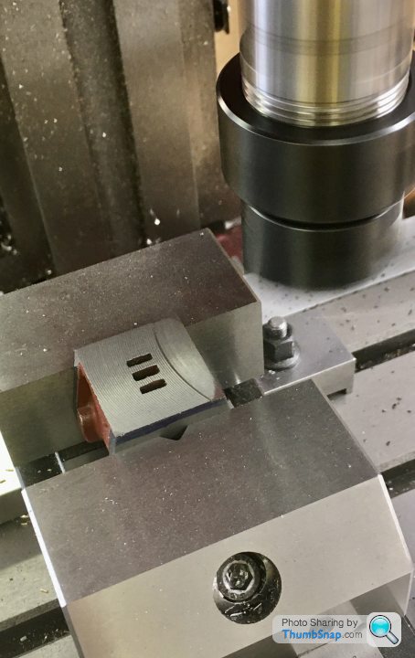
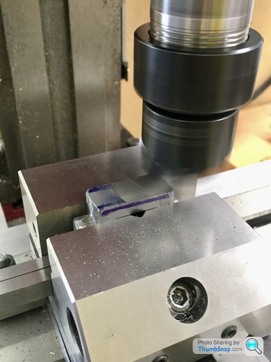
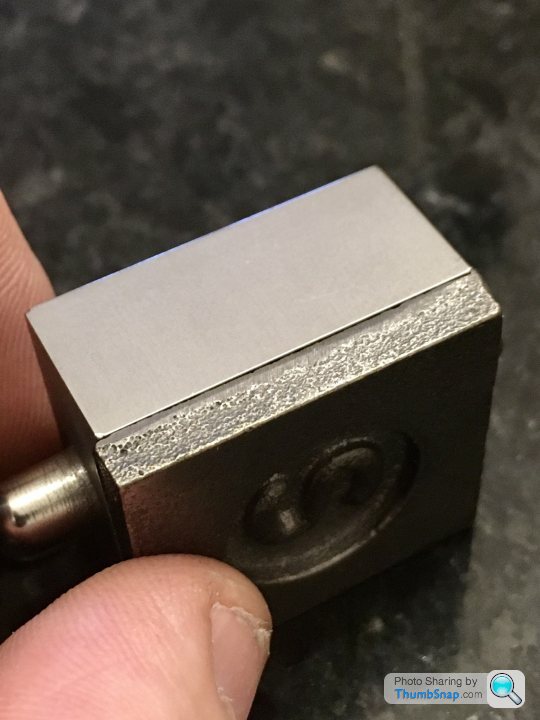
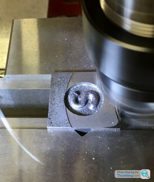
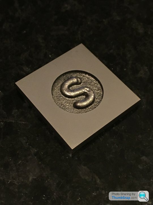
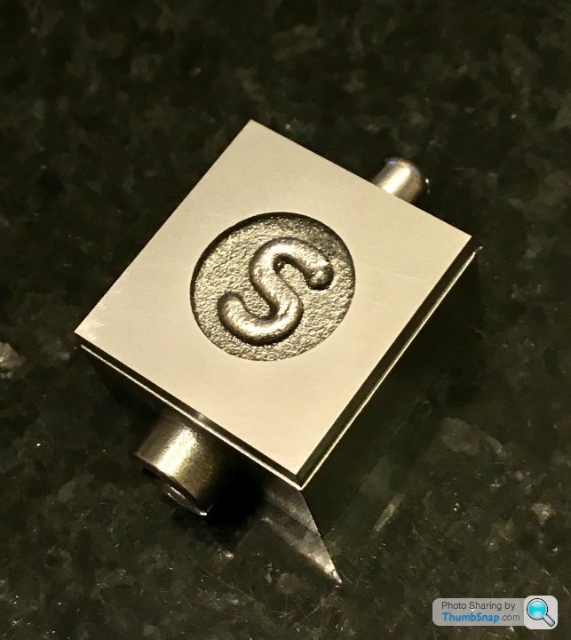
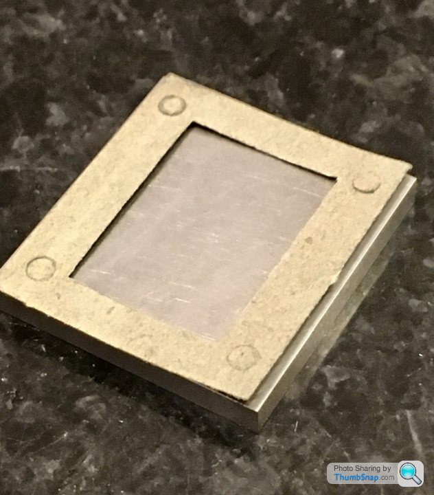
Didn’t have much time this evening, so I just squared and flatted the valve chest cover. First job was to mill the edges; first opposite pair I face-milled vertically, then clamped those faces horizontally and side-milled the other two. I made sure the “S” Circle was central:

Then fly-cut the faces to the right thickness:
The finish using the power feed is really nice - the leading cut obviously takes the majority of the material off, and the trailing cut just skims the surface. I think this must mean that my tramming efforts weren’t so bad after all. I finished by lightly rubbing on wet and dry on the surface plate:
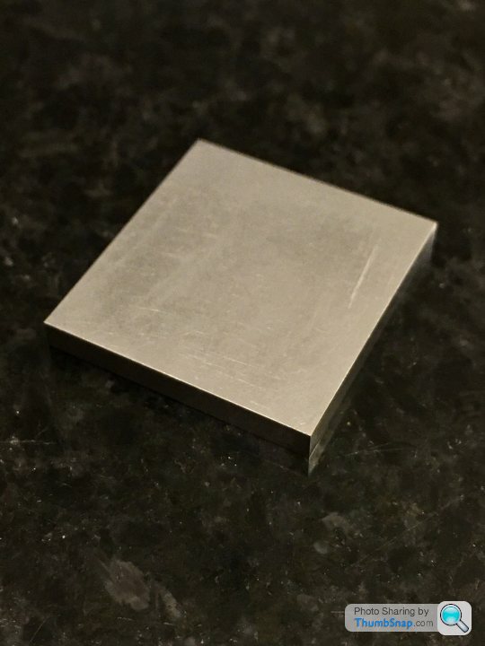
It’s a shame that to *just* completely clean up the side edges, it went undersize. I’ve tried to make the gap equal all around. Not to plan, but there was no way around it I could think of:
If Im careful, I can get the cover to stick to the chest on its own:

The gasket is not a great fit, and I suppose I may have to re-position the holes very slightly, but it shouldn’t be a big issue.
I’ll try to get the cylinder caps done next, then spend the weekend’s workshop time drilling all the mounting holes. I think calculation of all the co-ordinates will be at least a two-mug-of-tea job.
Then fly-cut the faces to the right thickness:
The finish using the power feed is really nice - the leading cut obviously takes the majority of the material off, and the trailing cut just skims the surface. I think this must mean that my tramming efforts weren’t so bad after all. I finished by lightly rubbing on wet and dry on the surface plate:
It’s a shame that to *just* completely clean up the side edges, it went undersize. I’ve tried to make the gap equal all around. Not to plan, but there was no way around it I could think of:
If Im careful, I can get the cover to stick to the chest on its own:
The gasket is not a great fit, and I suppose I may have to re-position the holes very slightly, but it shouldn’t be a big issue.
I’ll try to get the cylinder caps done next, then spend the weekend’s workshop time drilling all the mounting holes. I think calculation of all the co-ordinates will be at least a two-mug-of-tea job.
dhutch said:
dr_gn said:
Almost criminal now I've seen it. The valve chest is pissed up to the cylinder block too. It's almost like they have done it deliberately to make those less able feel good about themselves!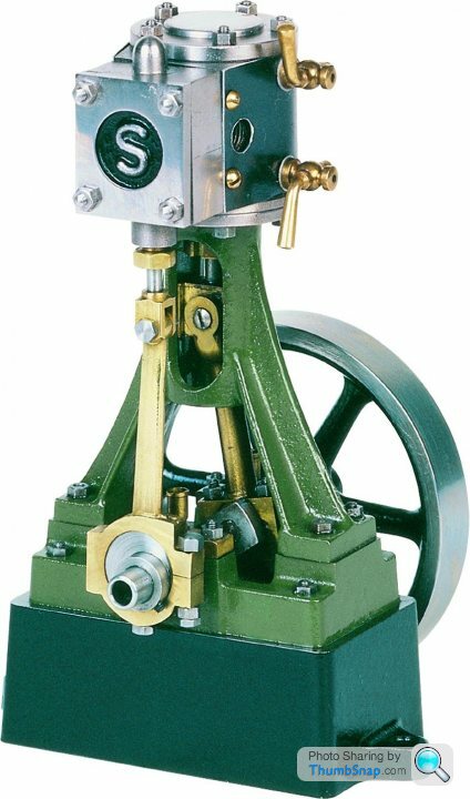
Daniel
Gassing Station | Scale Models | Top of Page | What's New | My Stuff