Stuart 10V Vertical Steam Engine
Discussion


A tip is that when you are doing drilling tapping,spotfacing etc. Lock up x,y and do all stages on one hole. That way is quicker and you don’t have to re-centre multiple times over the same hole. Also can use the chuck in the mill to hold the tap and know it is all square.
I know your baseplate is only temporarily bolted at present, it looks really professional if you have one and a half threads produding over each nut. There is a little trick to achieve this using a 7ba bolt double nutted at the end. It’s described on the Harold Hall build of the 10V. Anyway it is all looking good so far.

I know your baseplate is only temporarily bolted at present, it looks really professional if you have one and a half threads produding over each nut. There is a little trick to achieve this using a 7ba bolt double nutted at the end. It’s described on the Harold Hall build of the 10V. Anyway it is all looking good so far.
Thanks a Fourfold. The axes were locked in each position. I did a subsequent test in some plain steel and swapped the drills and cutter in a fixed position, but still got offset circles. I think I should have perhaps spot faced first.
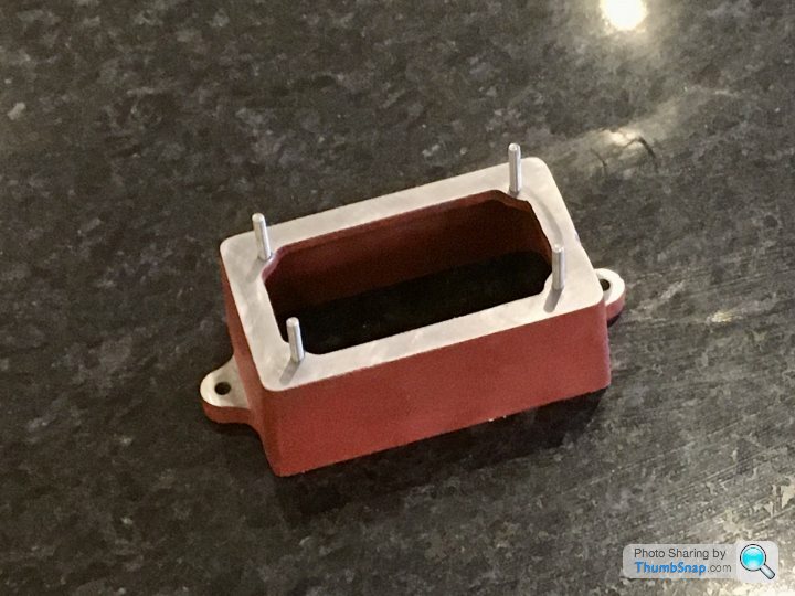
Yes, the studs are temporary - I think the actual ones supplied aren’t threaded far enough, so I had to use short ones for a test fit. I will make sure there are equal protrusions.
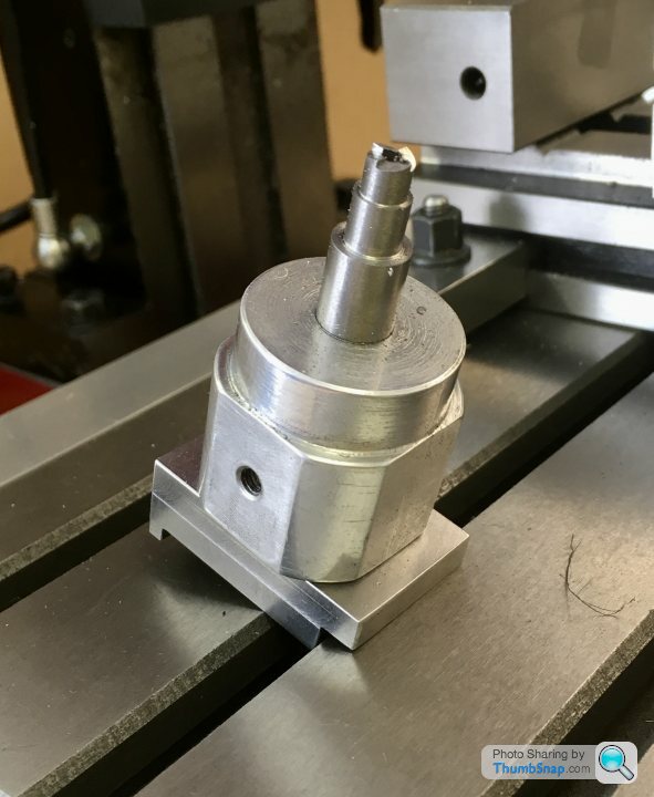
BTW the tap wrench in the photo is held exactly vertical over the hole with a spring-loaded centre held in the chuck. The studs are a close clearance fit in the sole plate holes, but it drops straight on, so at least that worked!
ETA I didn’t do all the operations for one hole at a time because I wanted to use the z depth stop for clearance drilling (just until the box bed surface), and more importantly to get the spot faces the same height above the base datum. If I was replacing drills etc there was no guarantee to fit them back at the right height. It did work, but no idea if it caused me the issue with off centres. Anyway, that was my reasoning.
Yes, the studs are temporary - I think the actual ones supplied aren’t threaded far enough, so I had to use short ones for a test fit. I will make sure there are equal protrusions.
BTW the tap wrench in the photo is held exactly vertical over the hole with a spring-loaded centre held in the chuck. The studs are a close clearance fit in the sole plate holes, but it drops straight on, so at least that worked!
ETA I didn’t do all the operations for one hole at a time because I wanted to use the z depth stop for clearance drilling (just until the box bed surface), and more importantly to get the spot faces the same height above the base datum. If I was replacing drills etc there was no guarantee to fit them back at the right height. It did work, but no idea if it caused me the issue with off centres. Anyway, that was my reasoning.
Edited by dr_gn on Friday 15th May 22:53
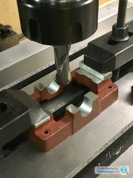
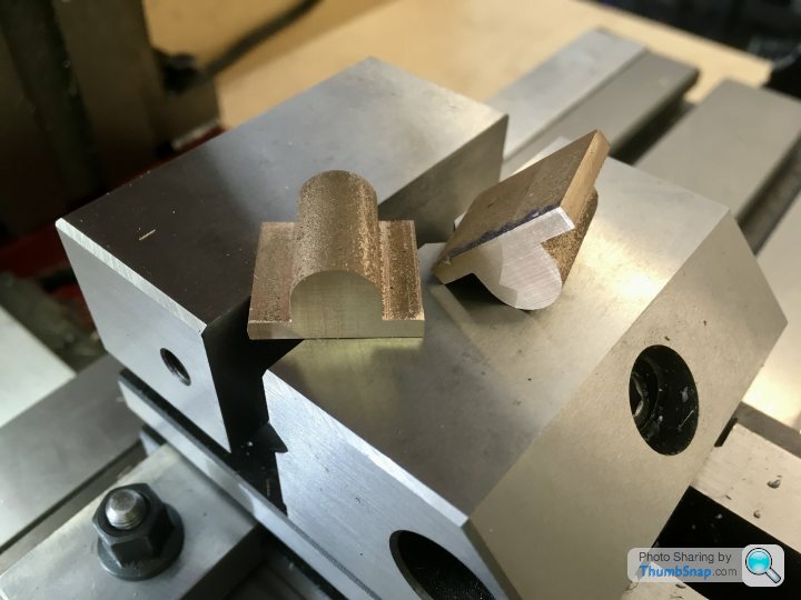
So after the false start trying to mill the main bearing recesses with the wrongly profiled tool, I tried again with a slightly smaller one (11mm, not 7/16”), and much better quality. Tested in aluminium:
Perfect, so on to the real thing:
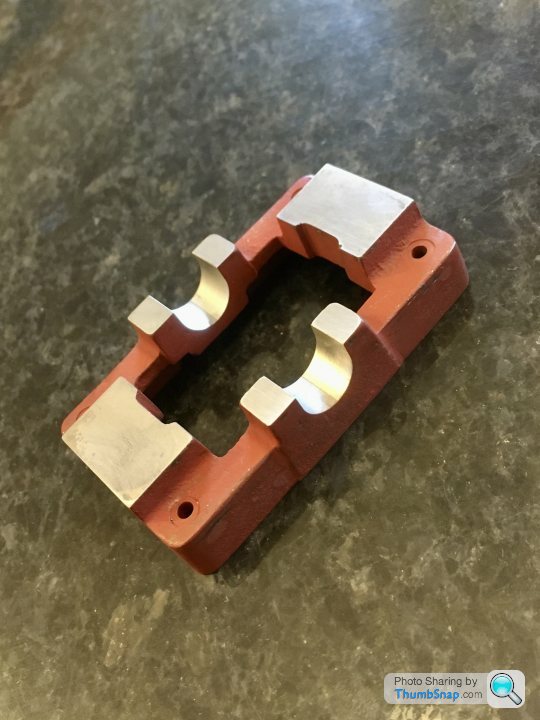
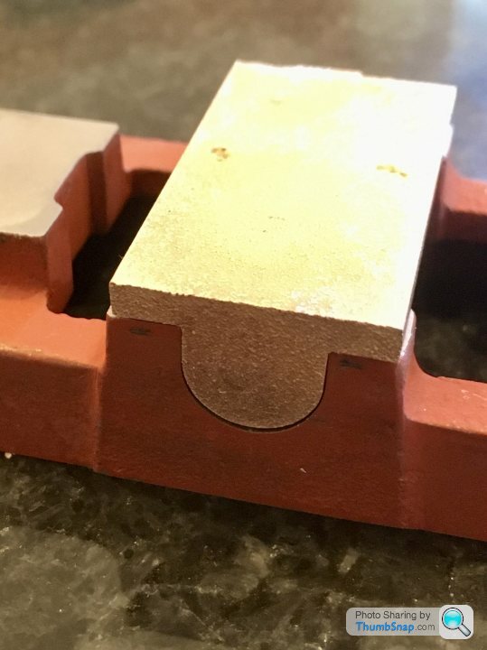
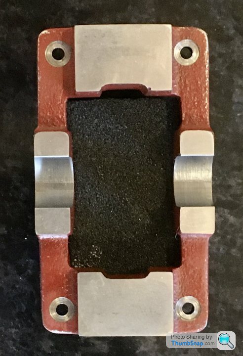
Went through the casting like it was butter. Unfortunately I centred the casting on the inner edges of the standard flats, double checking it with the insides of the cast bearing housing prongs. Result is that the brass is slightly offset to one side (but centred on the inside edges of the base). I should have used the outside edges of the bearing housing prongs.
Anyway a few passes with a fine file and it’s not really apparent, but lesson learned.
Onwards...
Perfect, so on to the real thing:
Went through the casting like it was butter. Unfortunately I centred the casting on the inner edges of the standard flats, double checking it with the insides of the cast bearing housing prongs. Result is that the brass is slightly offset to one side (but centred on the inside edges of the base). I should have used the outside edges of the bearing housing prongs.
Anyway a few passes with a fine file and it’s not really apparent, but lesson learned.
Onwards...
So today I re-made the spot facing tool, this time in Silver Steel from M-Machine, rather than Stainless (which I used by mistake last time). I've put all my known and marked steels in a box, the rest I've kept in reserve in 'deep storage' (the shed) just in case.

Made a jig for the milling machine to make the tool more acurately than I could by eye:
Then hardened by getting cherry red and dunking in brine:

Made a brass spigot this time, to keep everything concentric:
The test:

Perfect!

Also separated the main bearing stock and faced them off with my new ARC premium mill, which performed beautifully:

Made a jig for the milling machine to make the tool more acurately than I could by eye:
Then hardened by getting cherry red and dunking in brine:
Made a brass spigot this time, to keep everything concentric:
The test:
Perfect!
Also separated the main bearing stock and faced them off with my new ARC premium mill, which performed beautifully:
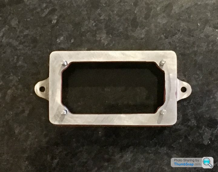
Still puzzling over how to retain the bearings on a mandrel and how to make a centering bar, so in the meantime I thought I'd finish the box bed. The mounting lugs are cast with dimples to drill to, but they didn't look central to me, and since thre are no dimensions given on the drawing I just got one with it the best I could.
I trued the casting up with a DTI along its long egde, and then milled 0.8mm off the top surfaces of the mounting lugs. I used 0.2mm cut depths. I did the side-to-side cuts by eye. A 12mm end mill covered the width of the lugs in one pass.
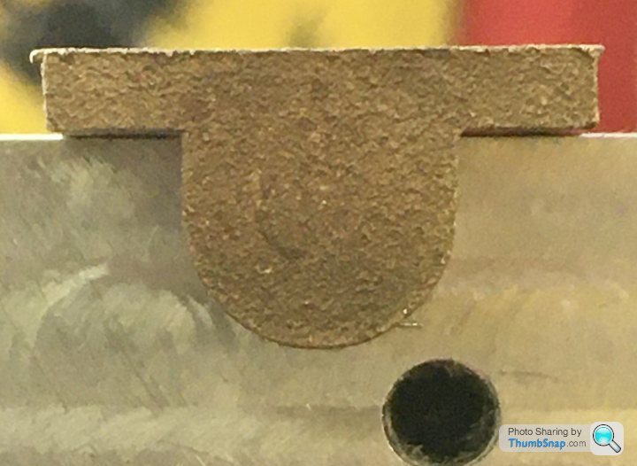
I wanted to get the mounting holes concentric with the end radii of the lugs, and since the cast radius doesn't cover 180 degrees, I opted to find a washer that was a good fit, and measure the diameter of that:

Then a fairly simple task of finding the middle of the casting, and using the edge finder to find the apex of the radius, then move to the centre using the DRO, centre & and drill to 3.5mm diameter:

Worked OK:
Pretty basic stuff, but one step further on.
I trued the casting up with a DTI along its long egde, and then milled 0.8mm off the top surfaces of the mounting lugs. I used 0.2mm cut depths. I did the side-to-side cuts by eye. A 12mm end mill covered the width of the lugs in one pass.
I wanted to get the mounting holes concentric with the end radii of the lugs, and since the cast radius doesn't cover 180 degrees, I opted to find a washer that was a good fit, and measure the diameter of that:
Then a fairly simple task of finding the middle of the casting, and using the edge finder to find the apex of the radius, then move to the centre using the DRO, centre & and drill to 3.5mm diameter:
Worked OK:
Pretty basic stuff, but one step further on.
I drilled and reamed bearing moulding, the cut slightly oversize each bearing. Then finished ends and shoulders on a tapered mandrel. To make tapered mandrel set topslide over to cut a teeny taper. That is enough to hold the bearing whilst you trim them. The brass cuts easily enough, you can superglue them if they are slipping. Don’t tap and drill bearing mounts until you have crankshaft, tap and drill with bearings on it to allow for alignment. Helps a bit if the u-channel is a bit not perfect!!
fourfoldroot said:
I drilled and reamed bearing moulding, the cut slightly oversize each bearing. Then finished ends and shoulders on a tapered mandrel. To make tapered mandrel set topslide over to cut a teeny taper. That is enough to hold the bearing whilst you trim them. The brass cuts easily enough, you can superglue them if they are slipping. Don’t tap and drill bearing mounts until you have crankshaft, tap and drill with bearings on it to allow for alignment. Helps a bit if the u-channel is a bit not perfect!!
Thanks for that FFR. I've seen a slightly simpler method on the ME forum, where you turn the mandrel to a transition fit, and wring the bearing onto it. Then you apply clamp force with a caphead bolt at the end. Seems straightforward, so I might try that. Of course you can't turn between centres, but the overhang is very short, and the bosses I'm turning dot realy do much in terms of needing concentricity. I'm not even sure I could re-align the tailstock again if I moved it!The crankshaft rod is supplied, and since I'm line reaming the fitted bearings as a pair, they shouldn't need any wiggle room; once theyre screwed down and reamed, that's it as far as alignment goes. When the bearings are removed for assembly, the crankshaft itself should re-align them assuming any slight play in the milled recesses. Obviously I'll mark the bearings so they go back in the same place.
At least that's the theory!
As you have said previously, there is many ways to skin a cat. I wouldn't offset the tailstock as it's a nuisance to reset. It's all about problem solving. Once you have done a build with words and music it gives you the confidence to tackle another project with your own ideas. There is no right way, but what works for you. The 10V is quite forgiving but has a few hard bits. I made three crankshafts before I got it right, eventually turning it from plate steel. Drilling the steam chest valve rod was an absolute pig, wandering drill points being the problem. If it was easy it wouldn't be satisfying.
fourfoldroot said:
As you have said previously, there is many ways to skin a cat. I wouldn't offset the tailstock as it's a nuisance to reset. It's all about problem solving. Once you have done a build with words and music it gives you the confidence to tackle another project with your own ideas. There is no right way, but what works for you. The 10V is quite forgiving but has a few hard bits. I made three crankshafts before I got it right, eventually turning it from plate steel. Drilling the steam chest valve rod was an absolute pig, wandering drill points being the problem. If it was easy it wouldn't be satisfying.
Yes, the more I read ‘how to build the 10V”, the more confusing it gets. It’s difficult to judge the result from videos or photos in terms of how well they run too.So thinking about the process of machining the bearings - I’ve got to turn bosses of different lengths on each end. It’ll be an intermittent cut from the outer ‘wings’ to the solid inner, so I’ll be moving the cross-slide in, cutting towards the Chuck, backing off, then incrementing the cross-slide in again before making another cut towards the Chuck.
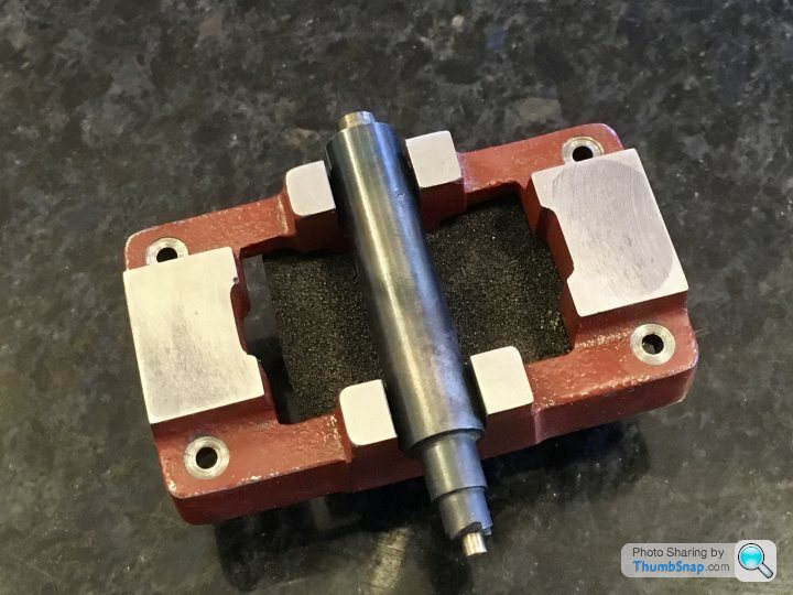
Trouble is, I need to make the cuts to the same length towards the Chuck, and I have no limit stop. I spent most of yesterday’s hobby time making one that screws to the headstock on the lathe. It’s mode of scrap aluminium and some 304 stainless rod. I found a spare quick-release toggle, so decided to use that as a clamp, rather than threading the bar. I did add a cap head screw and lock nut to the end for fine adjustment though. It took a long time to make, mainly because I made it up as I went. I should have drawn it all out, but sometimes that’s the way it happens:
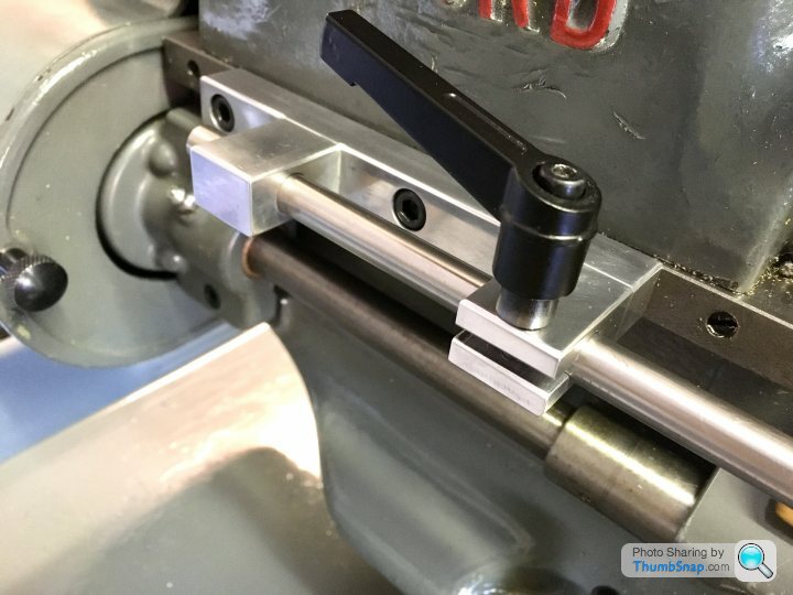


One lesson learned was that accurate alignment in every axis is critical for for consistent chamfering...next time I’ll get it better.
Now for the sprung centering rod...
Trouble is, I need to make the cuts to the same length towards the Chuck, and I have no limit stop. I spent most of yesterday’s hobby time making one that screws to the headstock on the lathe. It’s mode of scrap aluminium and some 304 stainless rod. I found a spare quick-release toggle, so decided to use that as a clamp, rather than threading the bar. I did add a cap head screw and lock nut to the end for fine adjustment though. It took a long time to make, mainly because I made it up as I went. I should have drawn it all out, but sometimes that’s the way it happens:
One lesson learned was that accurate alignment in every axis is critical for for consistent chamfering...next time I’ll get it better.
Now for the sprung centering rod...
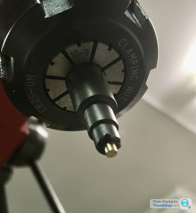
Cracked on with making a centering rod. I made it out of the remains of the 10mm silver steel I got for the spot-face tool, some brass off-cut and a random spring.


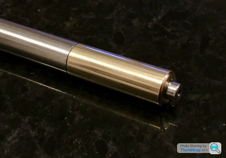

I 3D modelled this time so it only took a couple of hours to make. There is no play in the plunger so hopefully it might work. Not sure about the cone angles, but I suppose I’ll see if it works soon enough on the main bearings...
I 3D modelled this time so it only took a couple of hours to make. There is no play in the plunger so hopefully it might work. Not sure about the cone angles, but I suppose I’ll see if it works soon enough on the main bearings...
Ayahuasca said:
A reciprocating engine?
I have a 1950’s Boys Book of Model Making that includes a chapter and plans for building one of those from scratch. I think boys were more advanced back then.
Pretty much any engine with a piston and crankshaft is a reciprocting engine!I have a 1950’s Boys Book of Model Making that includes a chapter and plans for building one of those from scratch. I think boys were more advanced back then.
There are much simpler steam engines called oscillating engines, which don't have moving valves and eccentric cams etc; the rocking motion of a pivoted cylinder opens and closes steam ports. Mamod engines usually used them, and they are relatively straightforward to make without access to machine tools.
dr_gn said:
Ayahuasca said:
A reciprocating engine?
I have a 1950’s Boys Book of Model Making that includes a chapter and plans for building one of those from scratch. I think boys were more advanced back then.
Pretty much any engine with a piston and crankshaft is a reciprocting engine!I have a 1950’s Boys Book of Model Making that includes a chapter and plans for building one of those from scratch. I think boys were more advanced back then.
There are much simpler steam engines called oscillating engines, which don't have moving valves and eccentric cams etc; the rocking motion of a pivoted cylinder opens and closes steam ports. Mamod engines usually used them, and they are relatively straightforward to make without access to machine tools.
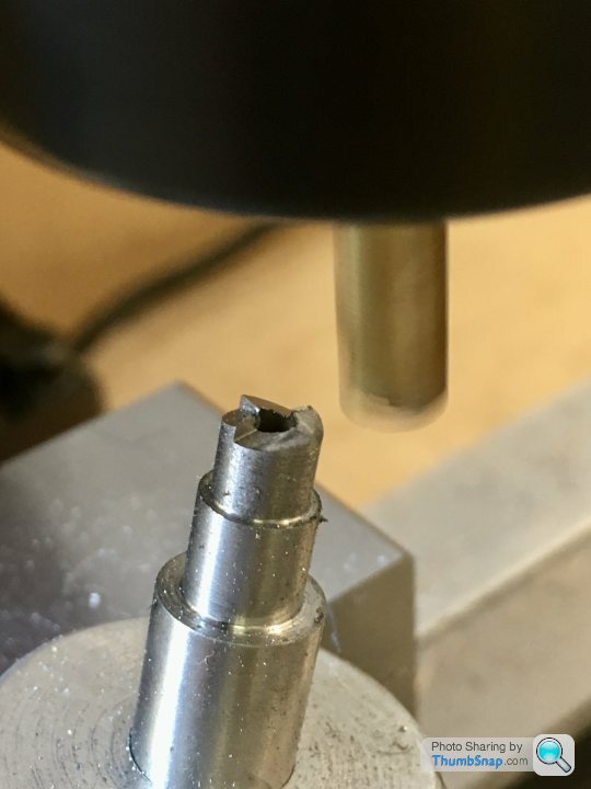
Marked out the centre of the bearing with caliper lines scribed on some blue marker. I had to use an eye loupe to get the punch central - my eyesight certainly isn't what it once was:

Next thing is to mount them in the 4 jaw chuck and align them with the centering rod.
Trouble is, the drawing seems to be wrong: It calls for the bearing width to be 7/16" (11.11 mm), but it's not that to start with - it's only about 10.95mm (hence me buying the wrong sized ball-nose mill). It then calls for the bosses that protrude from this to be 27/64" (10.72 mm) in diameter. So that only gives about a 0.12 mm wide step around the boss - totally out of proportion to the drawing; it should be approximately double that. I guess I could use the calculated step width from the drawing, but then that eats into the bearing face area of the bosses.
I wonder if the drawing is wrong, or they've changed the dimensions of their brass castings?
The brass castings vary over the years but the drawings don’t. The only critical dimension apart from the 9/32 hole down the middle, is the clearance for the crank webs, 5/8”. Even then when you are assembling you may need to turn a bit off so don’t repurpose your mandrel! The bosses are just prettifying,sonas long as they are equal.
I read somewhere a story where a whole O level metalwork class made them for their exam. They had a little side award where the winner was the one that ran on the lowest pressure . The one that won was the worst,sloppiest machined one. Because it had no frictional resitances it ran easily.
I read somewhere a story where a whole O level metalwork class made them for their exam. They had a little side award where the winner was the one that ran on the lowest pressure . The one that won was the worst,sloppiest machined one. Because it had no frictional resitances it ran easily.
Gassing Station | Scale Models | Top of Page | What's New | My Stuff