Paper Ship: Bismarck, HMV, 1:250
Discussion


Squirrelofwoe said:
dr_gn said:
Halmyre said:
dr_gn said:
Halmyre said:
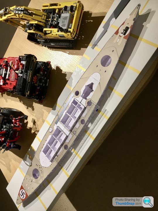
I'm slightly baffled as to why the German Navy would paint what are effectively two huge target markers on their shiny new warship. 
Two ways of looking at it I suppose: during the final battle to sink the Bismarck, Swordfish aircraft from Ark Royal initially attacked HMS Sheffield by mistake (luckily all the torpedoes failed to detonate). So maybe giant RAF roundels on the decks would have prevented that? Then again if the Swordfish crew knew the Bismarck had swastikas on the deck, why did they attack Sheffield? Answer must be that they wouldn't have been in a position to clearly see the decks during their attack runs.https://en.wikipedia.org/wiki/List_of_aircraft_of_...
Control of the Fleet Air Arm itself had only been transferred back over to the Admiralty a few months before WW2 broke out, previously it had been administered as a branch of the RAF. David Beatty as first sea lord had campaigned hard during the interwar years for control to be handed back over to the Admiralty without success. Consequently, few people were really aware as to the true potential of the aircraft carrier in the Royal Navy, or indeed the best way to use them. Many senior RN figures still saw the main use of the aircraft carrier as spotting for the fleet. Carrier-borne fighter aircraft were even considered very much secondary to the ship-based AA guns for defense. This led to episodes early in the war that would be considered suicidal within a very short space of time- i.e. carriers travelling through enemy controlled airspace with aircraft stowed beneath decks in their armoured hangers- they believed the AA guns were more than sufficient.
The success at Taranto, along with the loss of the Prince of Wales and Repulse really brought home the importance of carrier-based aviation to the Royal Navy (by the end of the war they had some 59 carriers and several thousand aircraft), but in 1939-41 they were along way behind the capabilities of the Japanese for example, and the idea of a Japanese-style carrier launched air attack on the Bismark using a large number of combined dive-bomber / torpedo aircraft was way beyond the capability of the Fleet Air Arm.
Even by 1942, the futility of the airborne operations against Operation Cerberus (the Channel Dash) showed how primitive the capability of the Fleet Air Arm still was even at that point in the war- a suicidal attack by six Swordfish biplanes.
This is partly what makes the successful torpedo strike from Ark Royal against Bismark so impressive for me- a mere handful of aircrew, flying already antiquated aircraft in absolutely appalling weather conditions, managing to get the all important hit that eventually led to the Bismark's demise. The previously mentioned mistaken attack on Sheffield also proving somewhat fortuitous as it highlighted the shortcomings of the magnetic-fused torpedoes, which were swapped out for old contact-based ones for the subsequent successful strike.
Obviously the remarkable success of this strike was also partly only possible due to the German's being even further behind in their appreciation of the importance of naval air power.
Digress aside, another fantastic model in progress!
https://en.wikipedia.org/wiki/Fairey_Swordfish#Atl...
"The low speed of the attacking aircraft may have acted in their favour, as they were too slow for the fire-control predictors of the German gunners, whose shells exploded so far in front of the aircraft that the threat of shrapnel damage was greatly diminished. At least some of the Swordfish flew so low that most of Bismarck's flak weapons could not depress enough to hit them."
So there was a lot of luck involved. Who would have thought that using an obsolete aircraft could work in your favour? Respect to the aircrew.
Squirrelofwoe said:
dr_gn said:
Thanks for that. I found this on Wikipedea, about the Swordfish:
https://en.wikipedia.org/wiki/Fairey_Swordfish#Atl...
"The low speed of the attacking aircraft may have acted in their favour, as they were too slow for the fire-control predictors of the German gunners, whose shells exploded so far in front of the aircraft that the threat of shrapnel damage was greatly diminished. At least some of the Swordfish flew so low that most of Bismarck's flak weapons could not depress enough to hit them."
So there was a lot of luck involved. Who would have thought that using an obsolete aircraft could work in your favour? Respect to the aircrew.
Indeed, and their incredibly low takeoff speed (comparative to newer monoplanes) meant that they could sometimes take off without the carrier even needing to sail into the wind. Their versatility kept them in service well after their intended replacement (and in fact through to the end of the war), but there is no doubting that they were well obsolete as a front line torpedo aircraft even at the start of the war.https://en.wikipedia.org/wiki/Fairey_Swordfish#Atl...
"The low speed of the attacking aircraft may have acted in their favour, as they were too slow for the fire-control predictors of the German gunners, whose shells exploded so far in front of the aircraft that the threat of shrapnel damage was greatly diminished. At least some of the Swordfish flew so low that most of Bismarck's flak weapons could not depress enough to hit them."
So there was a lot of luck involved. Who would have thought that using an obsolete aircraft could work in your favour? Respect to the aircrew.
As you say, the aircrew that flew them in those circumstances (and the Atlantic weather) deserve the utmost respect.
It was all going so well...
Then I tried to fit the decks, and it all went wrong. I’d never glued paper parts of that size before, and the PVA I used screwed the paper; the water in it soaked through and wrinkled the whole lot. Couldn’t live with it so...
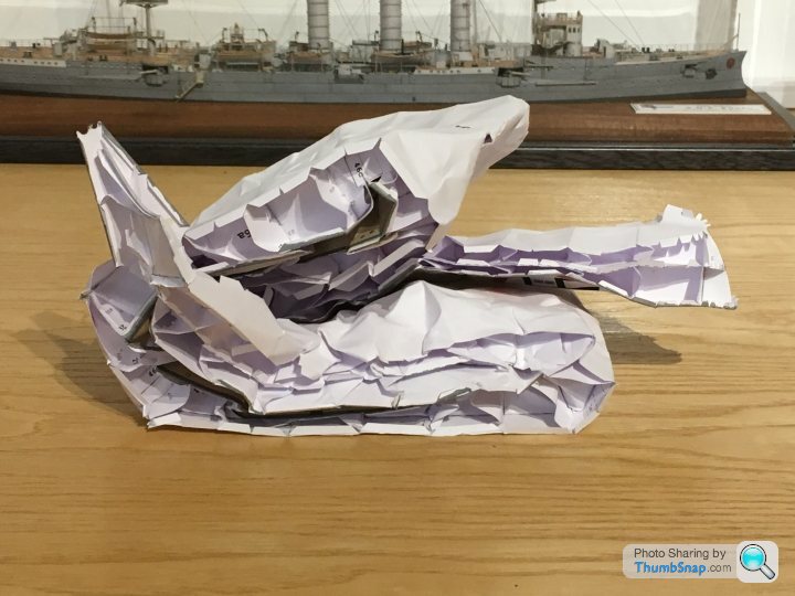
It took a surprising amount of physical and emotional effort to fold it up into a bin-sized ball, but there you go. So as of earlier this month, it’s shelf was empty:

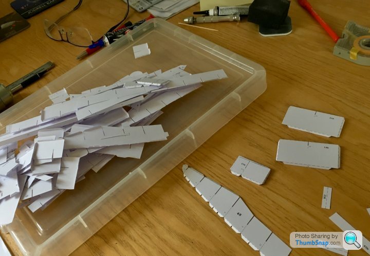
I continued cutting hull sides out - part of the grieving process I suppose:

Before buying another - I contacted HMV, who very kindly sent another, which I’ve set about re-building:


I’d almost forgotten about the swastika masking, all of which had to be re-done. As of yesterday, pretty much back to where I was , 4 weeks lost:

This time it’ll be UHU for the decks...
Then I tried to fit the decks, and it all went wrong. I’d never glued paper parts of that size before, and the PVA I used screwed the paper; the water in it soaked through and wrinkled the whole lot. Couldn’t live with it so...
It took a surprising amount of physical and emotional effort to fold it up into a bin-sized ball, but there you go. So as of earlier this month, it’s shelf was empty:
I continued cutting hull sides out - part of the grieving process I suppose:
Before buying another - I contacted HMV, who very kindly sent another, which I’ve set about re-building:
I’d almost forgotten about the swastika masking, all of which had to be re-done. As of yesterday, pretty much back to where I was , 4 weeks lost:
This time it’ll be UHU for the decks...
El stovey said:
dr_gn said:
El stovey said:
Wow.
So is that you back where you were before the blue incident then?
Yup.So is that you back where you were before the blue incident then?
4321go said:
I admire your perseverance, Doc. We can be certain that the eventual result will be stunning!
Thanks! It’s not the first time I’ve re-done a ship hull, although nothing like this size - the Corvette sides were wrongly printed, so I had to get another and fettle them. In fact I think HMV sent another one of those too after I pointed out the error. Zoobeef said:
Gutting to have to go back over old ground. Must feel good to know its progress from now.
Is it the engine on the left in one of your pictures?
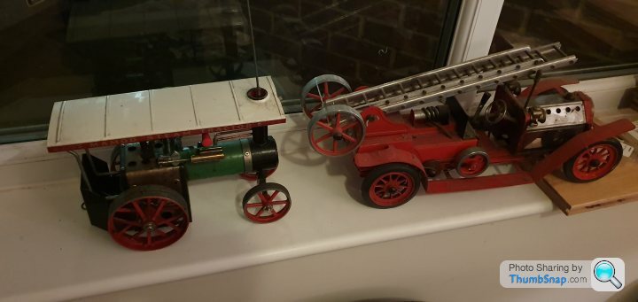
Yes, I remembered it was in a box and thought it deserved to be on show. So I cleaned it up and put it with my Wilesco engines.Is it the engine on the left in one of your pictures?
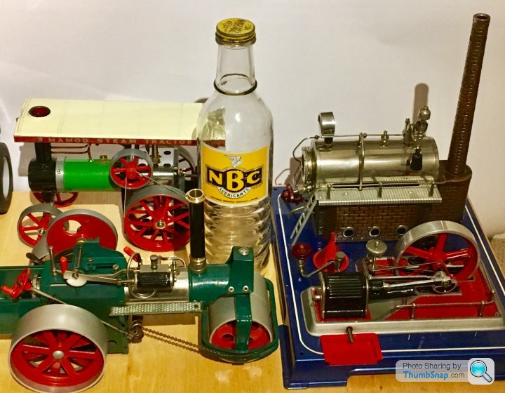
The steam roller is yet another project that needs finishing.
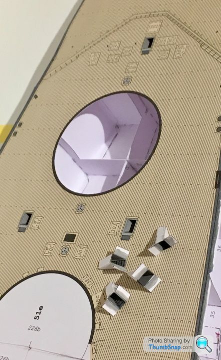
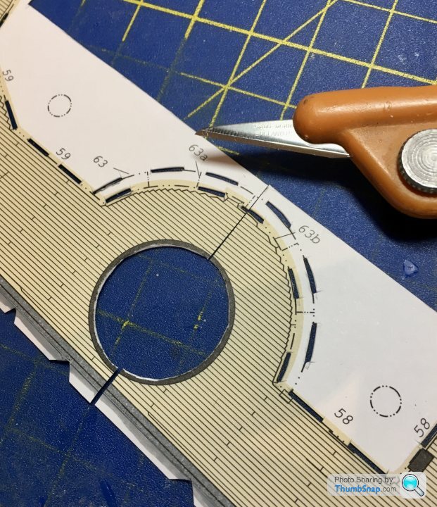
Tried a new technique for the deck joints this time. The planking is staggered, so any straight cuts/joints are obvious:
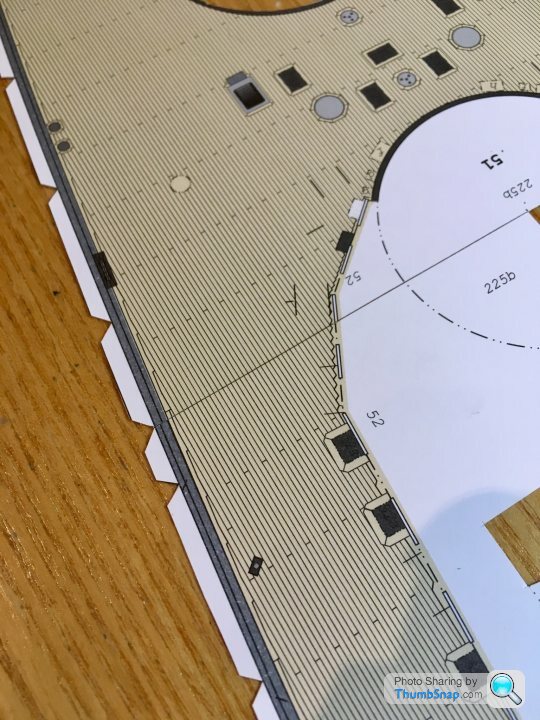
...but if you angle the scalpel blade so the chamfer on the rule side is vertical, or gives a slight undercut, it gets rid of the angled edges to the paper, which reduces the shadow that the resulting trough in the surface causes:
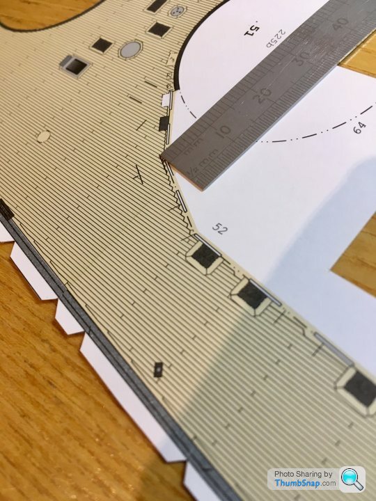
I think someone on a paper model forum mentioned it on my Corvette thread, but I didn’t fully appreciate what they were on about. Hopefully I can glue it neatly enough.
...but if you angle the scalpel blade so the chamfer on the rule side is vertical, or gives a slight undercut, it gets rid of the angled edges to the paper, which reduces the shadow that the resulting trough in the surface causes:
I think someone on a paper model forum mentioned it on my Corvette thread, but I didn’t fully appreciate what they were on about. Hopefully I can glue it neatly enough.

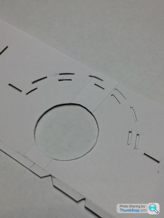
So this time - obviously - I’m using a different method of fitting the deck. The kit has you slot horizontal tabs in the four mid-ship deck pieces into corresponding slots cut in the vertical bits of the sub-structure. This makes it impossible to pre-assemble the decks and ‘drop’ the assembly into place in one go. I wanted to match the parts’ deck planking accurately on the bench, Using the new undercut joint method, then fit it.
For the record this was the sequence:
1) Cut all horizontal tabs off. These will be replaced once complete, to support the now unsupported edges.
2) Slightly relieve all non deck printed joint lines by slightly chamfering away from the joints, in order to give as much lateral flexibility as possible.
3) Start with the rear deck, and precisely match the first two mid-ship decks to each side. Don’t secure the mid-beam lateral joint.
4) Add the second mid-ship deck pieces to the first, again precisely matching the planking, and not securing the lateral joints.
5) Drop this assembly onto the sub-structure and check fit and alignment with centreline, bulkhead edges and gun turret wells.
6) Align and secure all lateral joints.
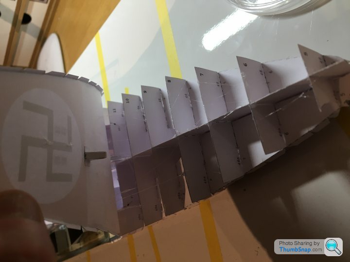
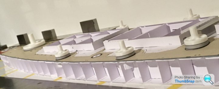
This is as far as I got:
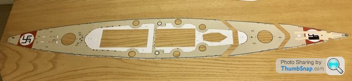
The deck is very slightly wavy, but should glue flat enough. I might make and temporarily fit the primary and secondary turret mounting cylinders, which will precisely align the deck with the corresponding wells in the hull substructure. Assuming everything aligns, I’ll then UHU the deck in place.
After that, the two front deck pieces will be added. I’ve left these until last, because the joint lines are angled, and are covered by breakwaters, making alignment less critical. Any length adjustment required can be made when fixing these two pieces.
That’s the theory anyway.
For the record this was the sequence:
1) Cut all horizontal tabs off. These will be replaced once complete, to support the now unsupported edges.
2) Slightly relieve all non deck printed joint lines by slightly chamfering away from the joints, in order to give as much lateral flexibility as possible.
3) Start with the rear deck, and precisely match the first two mid-ship decks to each side. Don’t secure the mid-beam lateral joint.
4) Add the second mid-ship deck pieces to the first, again precisely matching the planking, and not securing the lateral joints.
5) Drop this assembly onto the sub-structure and check fit and alignment with centreline, bulkhead edges and gun turret wells.
6) Align and secure all lateral joints.
This is as far as I got:
The deck is very slightly wavy, but should glue flat enough. I might make and temporarily fit the primary and secondary turret mounting cylinders, which will precisely align the deck with the corresponding wells in the hull substructure. Assuming everything aligns, I’ll then UHU the deck in place.
After that, the two front deck pieces will be added. I’ve left these until last, because the joint lines are angled, and are covered by breakwaters, making alignment less critical. Any length adjustment required can be made when fixing these two pieces.
That’s the theory anyway.
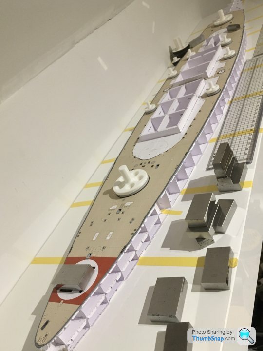
Primary and secondary turret base cylinders assembled and drying while weighted in alignment:
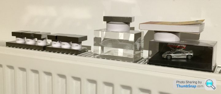
They corresponded pretty well to the cut-outs in the hull, so they’ll make good dowels for aligning the deck when securing it. Still in two minds about trying to cure the slight waviness in the deck - seems it might glue down, but if it doesn’t it’ll be too late to fix it...
They corresponded pretty well to the cut-outs in the hull, so they’ll make good dowels for aligning the deck when securing it. Still in two minds about trying to cure the slight waviness in the deck - seems it might glue down, but if it doesn’t it’ll be too late to fix it...
I’m a bit paranoid about fitting the deck after last time.
The primary and secondary turret mounting cylinders are a nightmare to keep round, and accurately adjusting their mounting holes in the deck is tricky with a scalpel. With this in mind I 3D printed some tapered plugs for the mounts, which keep them circular while they’re being mounted to the deck (important to avoid local warping). I also printed a pair of tapered reamers (sandpaper glued to the cone sides) to adjust the deck holes uniformly:
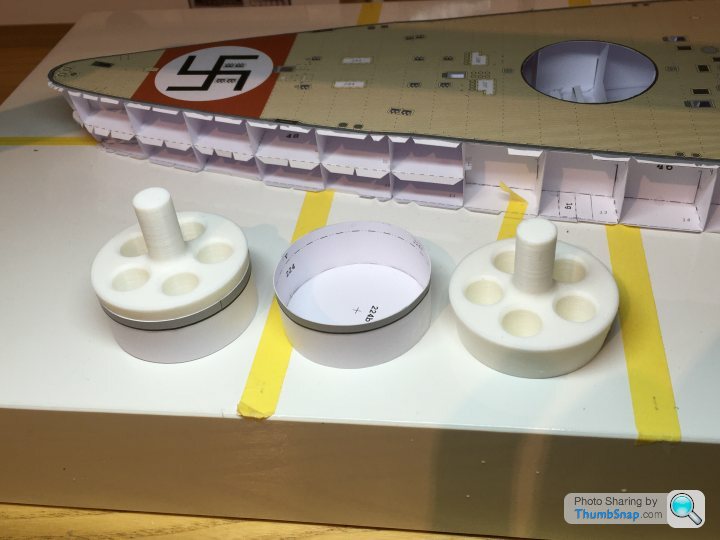
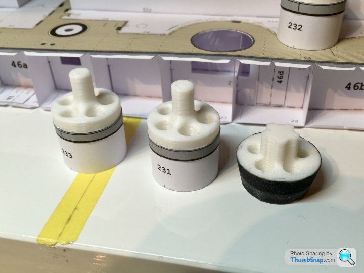

Result - pretty much as perfect a fit as you could get with paper, plus they will form accurate location dowels for the deck/hull side attachment:


The primary and secondary turret mounting cylinders are a nightmare to keep round, and accurately adjusting their mounting holes in the deck is tricky with a scalpel. With this in mind I 3D printed some tapered plugs for the mounts, which keep them circular while they’re being mounted to the deck (important to avoid local warping). I also printed a pair of tapered reamers (sandpaper glued to the cone sides) to adjust the deck holes uniformly:
Result - pretty much as perfect a fit as you could get with paper, plus they will form accurate location dowels for the deck/hull side attachment:
Turn7 said:
I think you need to start taking this seriuosly Doc, stop playing at it....... lol
Id love to have a 3d printer just to knock up random things like that....
Yep, a bit overkill, but since I’ve got a printer why not use it? This weekend I’ve used it for a prototype light sabre for my son, some mirrors for a model car and the “Bismarck butt plugs”).Id love to have a 3d printer just to knock up random things like that....
Turn7 said:
dr_gn said:
Turn7 said:
I think you need to start taking this seriuosly Doc, stop playing at it....... lol
Id love to have a 3d printer just to knock up random things like that....
Yep, a bit overkill, but since I’ve got a printer why not use it? This weekend I’ve used it for a prototype light sabre for my son, some mirrors for a model car and the “Bismarck butt plugs”).Id love to have a 3d printer just to knock up random things like that....
AW111 said:
No offence to dr_gn's excellent work, but a cardboard ship model always reminds me of this:
The front fell off
Let's hope yours does better .
.
Strange you should say that because HMV do a model of an oil tanker:The front fell off
Let's hope yours does better
.
...and the front does actually fall off:

It looks a good model now I look at it more carefuly than I did before.
So the time has come for deck fitting part deux.
There was a slight warp in the deck, so I chased it around with various rulers and weights until it was around a secondary turret hole. I the sliced the deck locally through the hole and could then see the extent of the mis-match:

Then marked and sliced it using the bevelled edge technique:

Backed up with plain printer paper:
Not forgetting to add the deck steps:

Then crunch time - sticking the deck, this time with UHU. I worked middle to edges, front to back in stages:
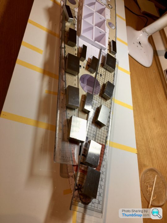
Despite daubing the substructure in glue with a cocktail stick, no wrinkles!
I re-reamed the modified deck hole so it was circular again, and temporarily fitted the turret mounting cylinders with their jigs:
Still to add the front two bits, but should be a trivial task. The cut-and-shut didn’t fully get rid of the warp in the end, but it’s in a fairly unobtrusive place, so it’s manageable now I think.
There was a slight warp in the deck, so I chased it around with various rulers and weights until it was around a secondary turret hole. I the sliced the deck locally through the hole and could then see the extent of the mis-match:
Then marked and sliced it using the bevelled edge technique:
Backed up with plain printer paper:
Not forgetting to add the deck steps:
Then crunch time - sticking the deck, this time with UHU. I worked middle to edges, front to back in stages:
Despite daubing the substructure in glue with a cocktail stick, no wrinkles!
I re-reamed the modified deck hole so it was circular again, and temporarily fitted the turret mounting cylinders with their jigs:
Still to add the front two bits, but should be a trivial task. The cut-and-shut didn’t fully get rid of the warp in the end, but it’s in a fairly unobtrusive place, so it’s manageable now I think.
lufbramatt said:
The sheer size of this has just dawned on me- one of my colleagues bought a Tamiya 1:350 Yamato last week and that’s massive, this is way bigger!
I can’t begin to fathom how you have he patience to see these builds through!
Yes it’s a bit on the large size - just over 1m. I’ve put an Ikea shelf up to keep it on just for this build.I can’t begin to fathom how you have he patience to see these builds through!
Someone I know has the Tamiya 1:350 Bismarck, this one is infinitely more detailed. Unfortunately all that detail has to be cut out, folded up and glued together...
Edited by dr_gn on Thursday 16th January 21:56
Turn7 said:
Is UHU still the hideous stringy, gets everywhere stuff I remember from my childhood ?
Yes, it’s absolutely hopeless to work with on anything more critical than large bits of model which will never be seen again.It certainly does the job when used in the right places though.
Gassing Station | Scale Models | Top of Page | What's New | My Stuff