Schumacher CAT XLS build
Discussion


Thanks for the tip, have done the front suspension last night so the turnbuckles are next on the list. I vaguely remember doing that on my SST axis touring car but had completely forgotten about it! It’s just the track rods on this as the upper arms are fixed length.
Edited by lufbramatt on Friday 22 May 16:47
Back in the day, I was glad of the lack of upper wishbone adjustment. I remember the optima mid (The other popular car at my club) had both adjustable length and mounting point for the upper link. I also remember the pain my friends went through trying to get a decent set-up with them!
The CAT just seemed to work fine out of the box with relatively little to adjust /mess up.
The CAT just seemed to work fine out of the box with relatively little to adjust /mess up.
Back in the day the ProCat would build with a gnats more neggie on one side than the other (I cant recall which - Groomi will know) and as you couldn’t adjust anything you either filed the opposite spacer block to match or ran with 2 thin washers to stand the sleepy corner up.
My XLS runs Groomi’s adjustable top wishbones front and back which are a lovely mod, his ballraced steering is great too.
My XLS runs Groomi’s adjustable top wishbones front and back which are a lovely mod, his ballraced steering is great too.
If I feel the need for adjustable upper arms I'll either make something from acetal on the milling machine at work (assuming I ever get back to the office!) or CAD something up and get my friendly prototyping guy to 3D print it in a suitable material. The turnbuckles and ball sockets are pretty cheap.
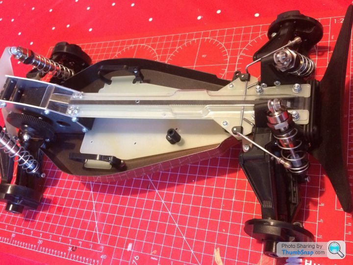
Turnbuckles on and roughly adjusted. Was a bit confused as the manual says to set the front track rod arms to 38mm but doing this resulted in a huge amount of toe in, then I remembered I had fitted the wide track steering link which is longer than the kit part so the track rods have to be shorter :-)
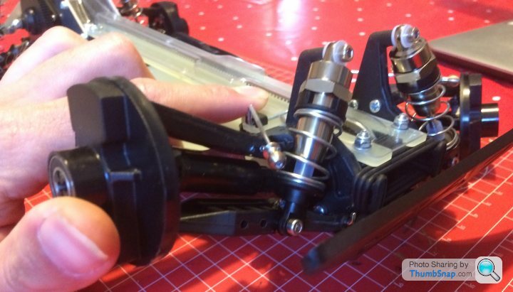
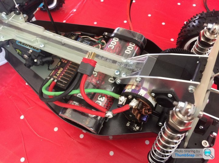
Came accross this issue though when I put the servo mounts in, the right hand brace that links the top and bottom decks is exactly where the wires come out of my servo. (Look where the silver screw is) I can either space the servo over to the left by putting washers between the servo and the posts or leave out the brace. Thoughts?

Came accross this issue though when I put the servo mounts in, the right hand brace that links the top and bottom decks is exactly where the wires come out of my servo. (Look where the silver screw is) I can either space the servo over to the left by putting washers between the servo and the posts or leave out the brace. Thoughts?
lufbramatt said:
Turnbuckles on and roughly adjusted. Was a bit confused as the manual says to set the front track rod arms to 38mm but doing this resulted in a huge amount of toe in, then I remembered I had fitted the wide track steering link which is longer than the kit part so the track rods have to be shorter :-)
Came accross this issue though when I put the servo mounts in, the right hand brace that links the top and bottom decks is exactly where the wires come out of my servo. (Look where the silver screw is) I can either space the servo over to the left by putting washers between the servo and the posts or leave out the brace. Thoughts?
Does the steering servo location allow you to rotate it though 180 degrees?Came accross this issue though when I put the servo mounts in, the right hand brace that links the top and bottom decks is exactly where the wires come out of my servo. (Look where the silver screw is) I can either space the servo over to the left by putting washers between the servo and the posts or leave out the brace. Thoughts?
If so, do that, and the servo cable output will be at the other end, and hopefully out of harms way allowing you to put that post back in.
Then just make a longer linkage from the servo output horn to the steering actuator.
Just musing as I’m thinking of doing something similar on one of mine as the servo will not sit level as the cable output is pushing it up In the mount.
Oh and I’m bored at 6 am in the morning because I was up with the larks again today,
lufbramatt said:
Good idea- but the servo output is already at the farthest away (from the steering mechanism) end of the servo- so flipping it over would mean a very short link to the steering crank arm on the chassis- about 15mm- which wouldn’t work unfortunately.
Ah I see Matt, not knowing what the link set up was like of your type of car, it was more a guess than a solution!
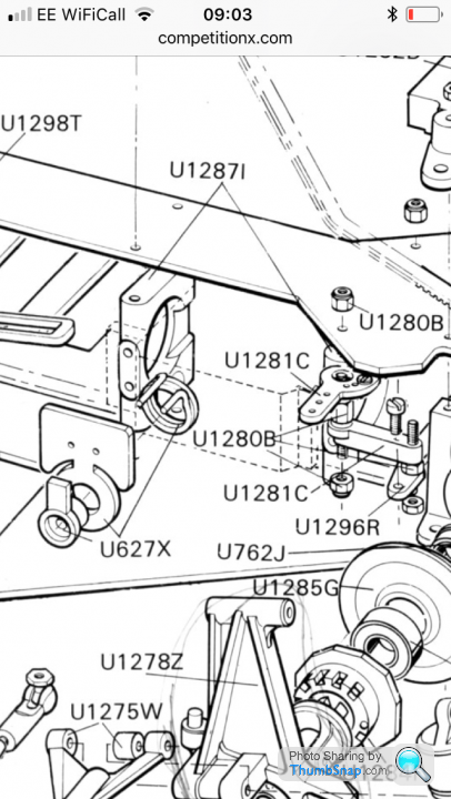
Here is the step from the original manual. Looks like they only used one support and described it as the servo mount rather than structural support of the chassis.
Weird how I always remember running the servo facing the other way acting on the RHS of the steering linkage, can't remember why, likely to be broken mounting tabs though rather than fitment
Weird how I always remember running the servo facing the other way acting on the RHS of the steering linkage, can't remember why, likely to be broken mounting tabs though rather than fitment
Personal preference as to which side you mount the servo, depending on how you want to mount your electrics. Very few ESC's back in the day could fit between the servo and the battery and under the top deck, so it would have to go at an angle behind the servo - so it depended whether you wanted it motor side or opposite.
Soldering iron out last night, electronics all in, getting closer to finishing 
Need to replace all the tamiya plugs on our batteries with deans. Servo choke wired up to esc, and battery/motor cables re done to fit the cat chassis layout better. Schottky diode and motor suppressor caps fitted too. Still need to tidy up the signal wires from the receiver to servo and esc and wrap some self amalgamating tape around the joint in the red wire but ran out of evening.
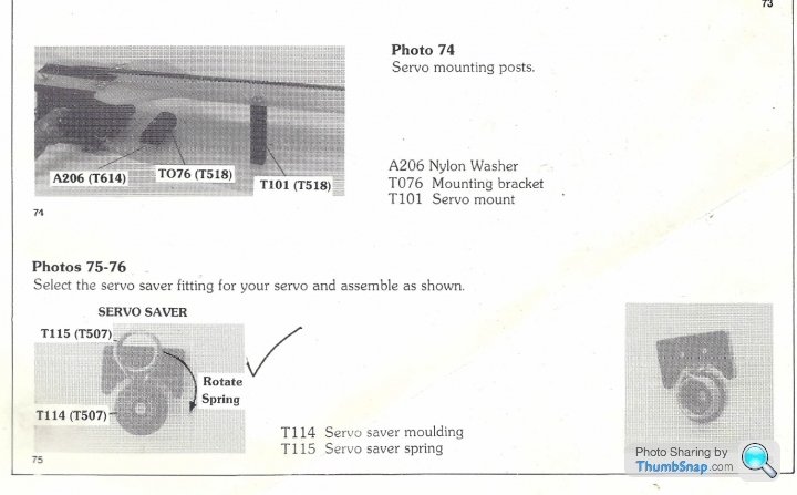
Just waiting on a different servo saver (kit one is 25 spline, I need a 23 spline for the KO servo) then I can go for a test drive!
Need to replace all the tamiya plugs on our batteries with deans. Servo choke wired up to esc, and battery/motor cables re done to fit the cat chassis layout better. Schottky diode and motor suppressor caps fitted too. Still need to tidy up the signal wires from the receiver to servo and esc and wrap some self amalgamating tape around the joint in the red wire but ran out of evening.
Just waiting on a different servo saver (kit one is 25 spline, I need a 23 spline for the KO servo) then I can go for a test drive!
Edited by lufbramatt on Tuesday 26th May 09:34
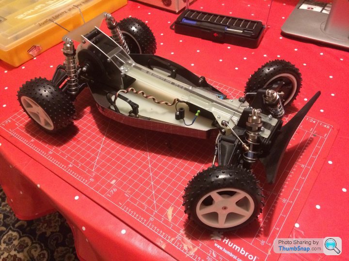
Got the correct servo saver eventually through the post so finished the rolling chassis tonight and had a quick buzz round the garden :-)
Drives ok but it seems really noisy? Seems to be a whining noise coming from the spur gear. Belts don't seem to be slipping. Are they all like this or have I done something wrong- gear mesh too loose/tight?
Pinion is a 25t that I had on my SST axis touring car which appears to use the same 48dp tooth pitch as the re-re CAT.
lufbramatt said:
Got the correct servo saver eventually through the post so finished the rolling chassis tonight and had a quick buzz round the garden :-)
Drives ok but it seems really noisy? Seems to be a whining noise coming from the spur gear. Belts don't seem to be slipping. Are they all like this or have I done something wrong- gear mesh too loose/tight?
Pinion is a 25t that I had on my SST axis touring car which appears to use the same 48dp tooth pitch as the re-re CAT.
That type of noise Is normally mismatched motor gear to main gear, ie 48dp to another type ie 24dp.Drives ok but it seems really noisy? Seems to be a whining noise coming from the spur gear. Belts don't seem to be slipping. Are they all like this or have I done something wrong- gear mesh too loose/tight?
Pinion is a 25t that I had on my SST axis touring car which appears to use the same 48dp tooth pitch as the re-re CAT.
But the most common one is over meshed motor gear to main gear.
Check it for back lash, and make sure the metal motor gear isn’t biting into the plastic main gear.
Thanks Nigel- Nail on the head with your first comment! I had been an idiot and managed to pick up a Tamiya pinion from my TA-03 instead of the Schumacher pinion! Very similar pitch but slightly different. Not run it again but feels instantly better rotating things by hand.
I only ran it for about 20 seconds earlier as it was obvious something wasn't right so don't think I've damaged anything.
I only ran it for about 20 seconds earlier as it was obvious something wasn't right so don't think I've damaged anything.
lufbramatt said:
Thanks Nigel- Nail on the head with your first comment! I had been an idiot and managed to pick up a Tamiya pinion from my TA-03 instead of the Schumacher pinion! Very similar pitch but slightly different. Not run it again but feels instantly better rotating things by hand.
I only ran it for about 20 seconds earlier as it was obvious something wasn't right so don't think I've damaged anything.
Blimey I’m two for two on getting my hunches right, I better have a go on the lottery.,I only ran it for about 20 seconds earlier as it was obvious something wasn't right so don't think I've damaged anything.
At least the main gear is easy enough and relatively cheap too, for a Quick replacement.
We’ve all done it though doesn’t matter how long you have been building models, it’s still easy to make really simple mistakes, so don’t sweat it.
I did it yesterday with my Kyosho Spada 09 build, I managed to mount the rear axle bearing hangers 180 degrees out, ie put them on back front, instead of front back!
You should be fine with the gear it it hasn’t taken any big chunks out of the plastic.
Gassing Station | Scale Models | Top of Page | What's New | My Stuff