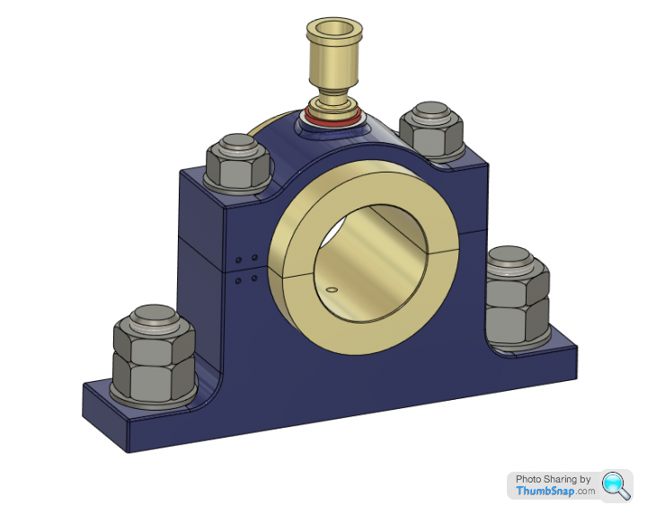
Stuart Twin Victoria (Princess Royal) Mill Engine
Discussion


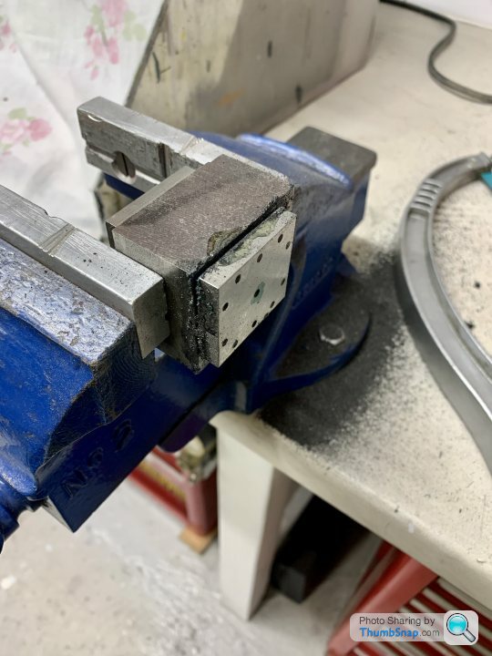
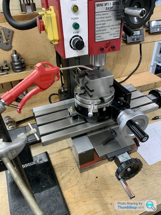
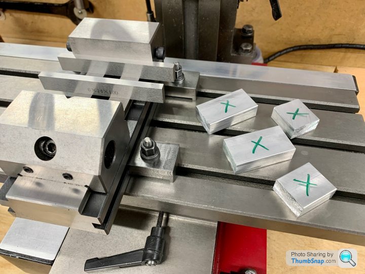
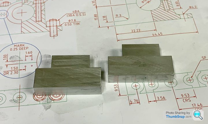
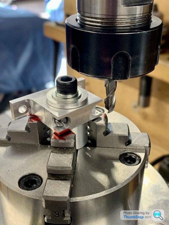
Then setup in the rotary table, centering on the oiler hole. This is what the blanks looked like:
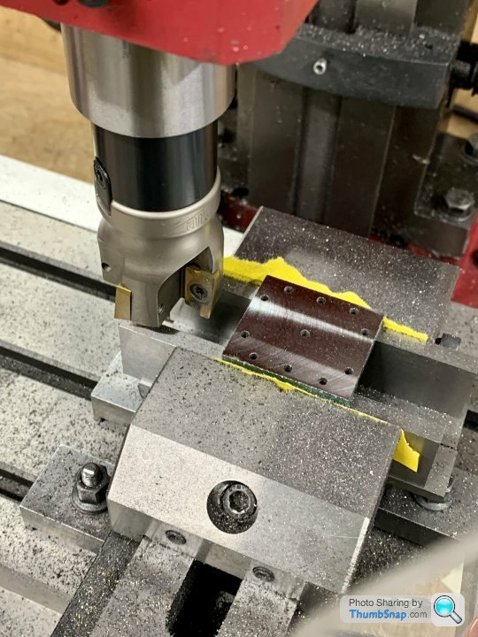
I set up an air line to blow the chips away, I didn’t want them getting stuck in the recess:
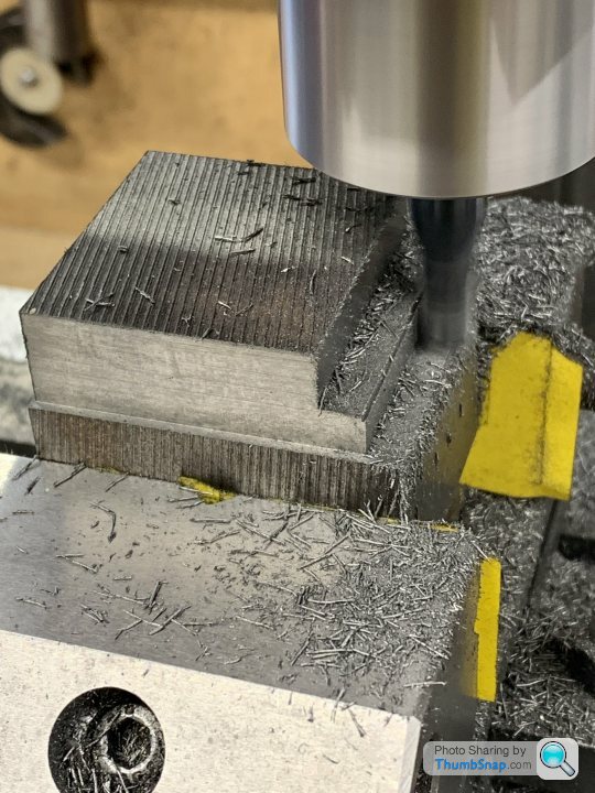
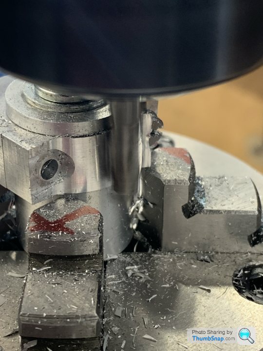
Milling the outline:
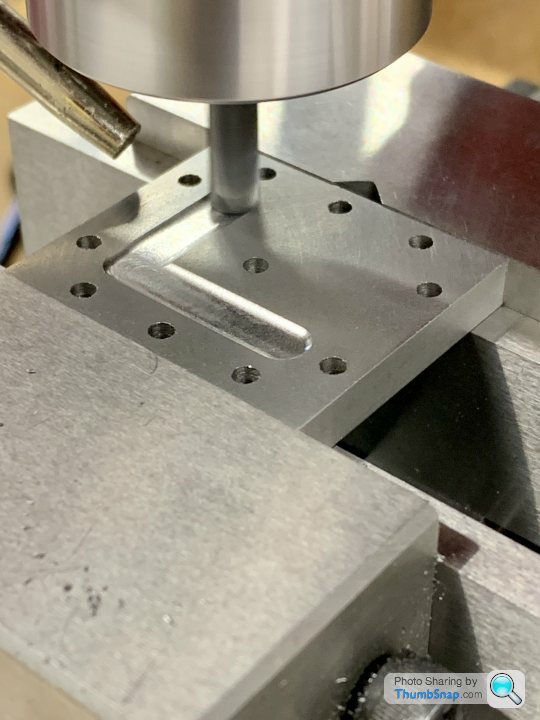
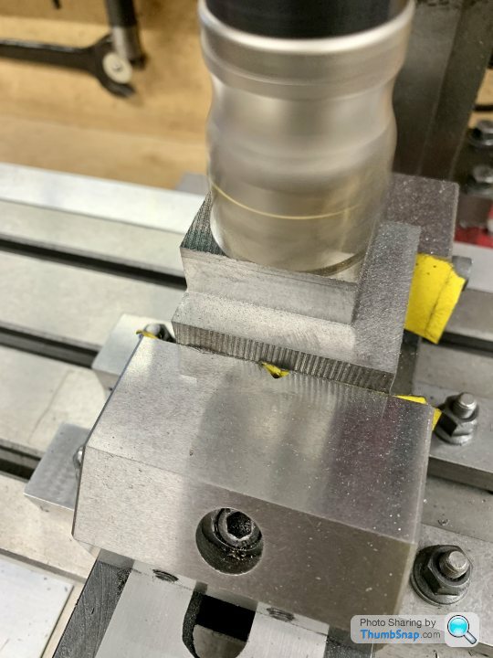
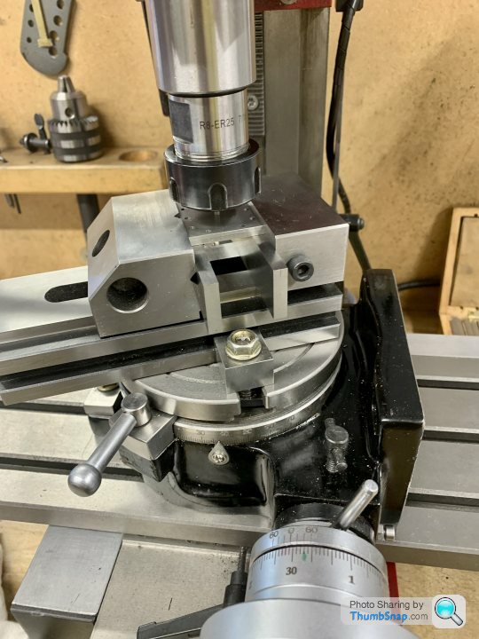
Then rotated the table around the central hole to give a radiussed pad:
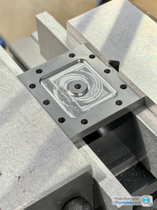
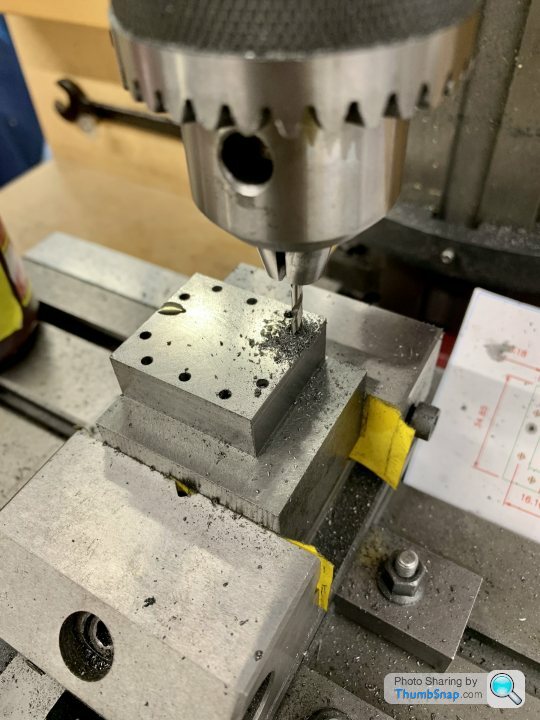
Then tapped the 5BA threads for the oilers (which I need to make):
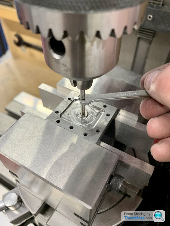
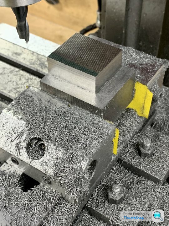
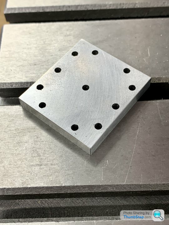
Then faced to the correct thickness:
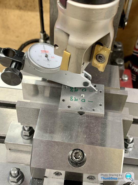
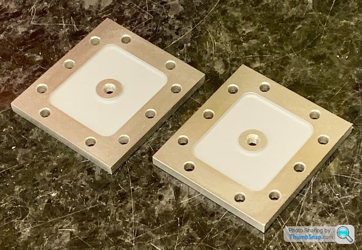
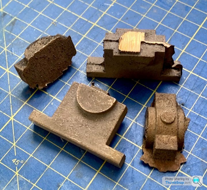
Result:

Primed:
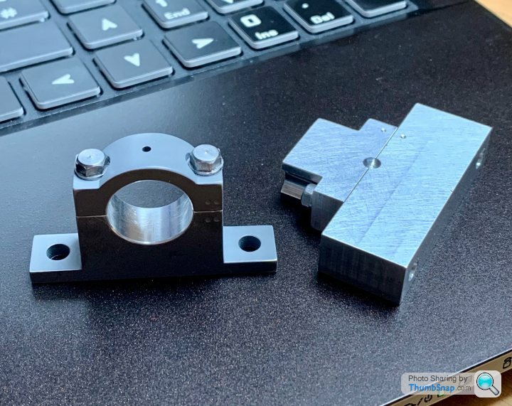
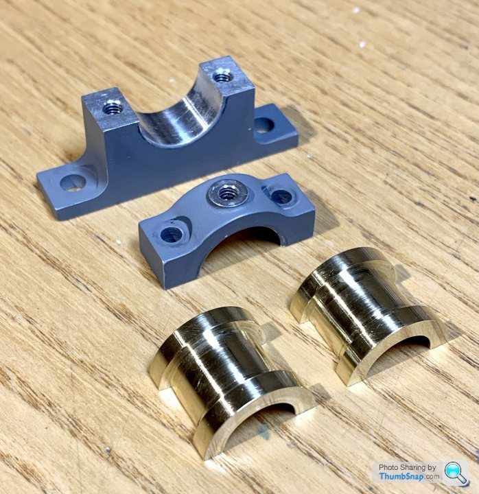
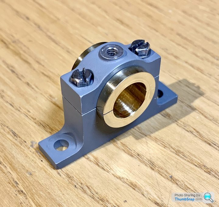
Test fitted to the other bits:
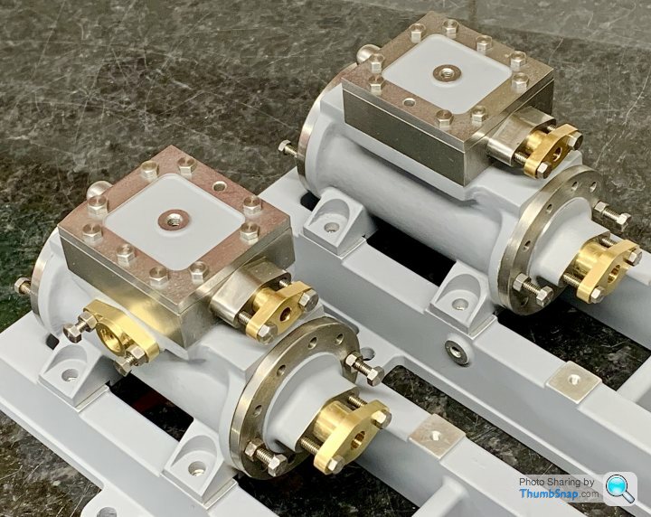
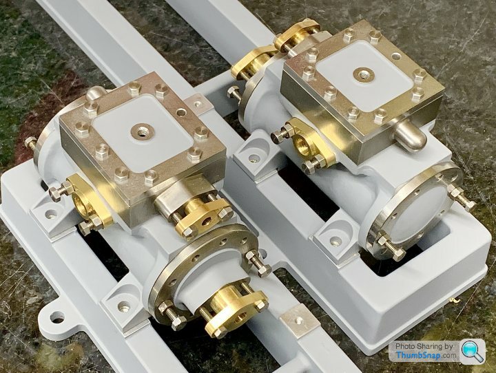
Might not look much at the moment, but there is a lot of work just in those assemblies…
I set up an air line to blow the chips away, I didn’t want them getting stuck in the recess:
Milling the outline:
Then rotated the table around the central hole to give a radiussed pad:
Then tapped the 5BA threads for the oilers (which I need to make):
Then faced to the correct thickness:
Result:
Primed:
Test fitted to the other bits:
Might not look much at the moment, but there is a lot of work just in those assemblies…
MKnight702 said:
dr_gn said:
Might not look much at the moment, but there is a lot of work just in those assemblies…
That's a slight understatement of the work you have done. If I had a quarter of the skills you have I would be a very happy man.dudleybloke said:
Looking very nice indeed.
I've never used a mill smaller than a Bridgeport but I've used a few shonky ones and know what you're going through with regards to machine limitations.
You are doing a superb job with what you've got and seem to have picked up the feel of it pretty quickly.
Thanks - both the lathe and the mill have their foibles, but I guess compensating of them is just part of the process.I've never used a mill smaller than a Bridgeport but I've used a few shonky ones and know what you're going through with regards to machine limitations.
You are doing a superb job with what you've got and seem to have picked up the feel of it pretty quickly.
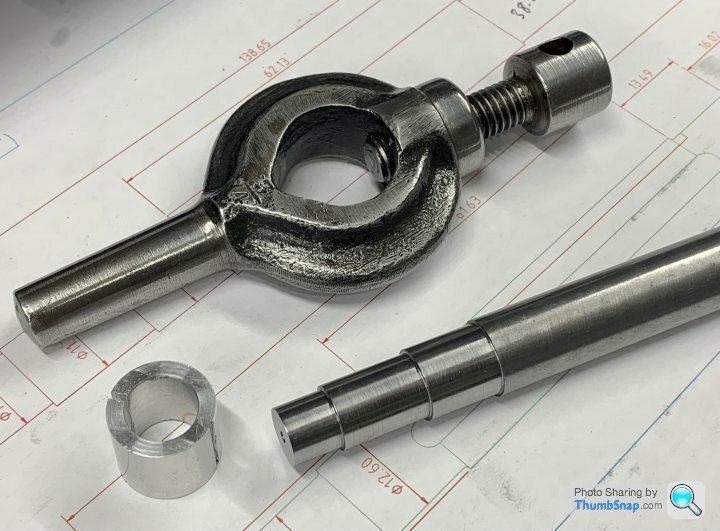
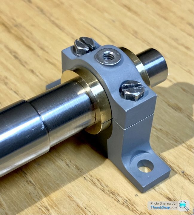
Bit of an annoying setback with this. I started on the main bearings, which I bought as gunmetal castings:
But it turns out there was a design change in the distant past, which means that they aren'r really suitable for this engine (too tall, plus the boss width is short on mine).
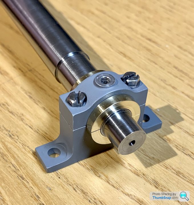
So, with some advice from the ME forum, I opted to make them from scratch out of aluminium, with separate split brass bearings. So I made a start:
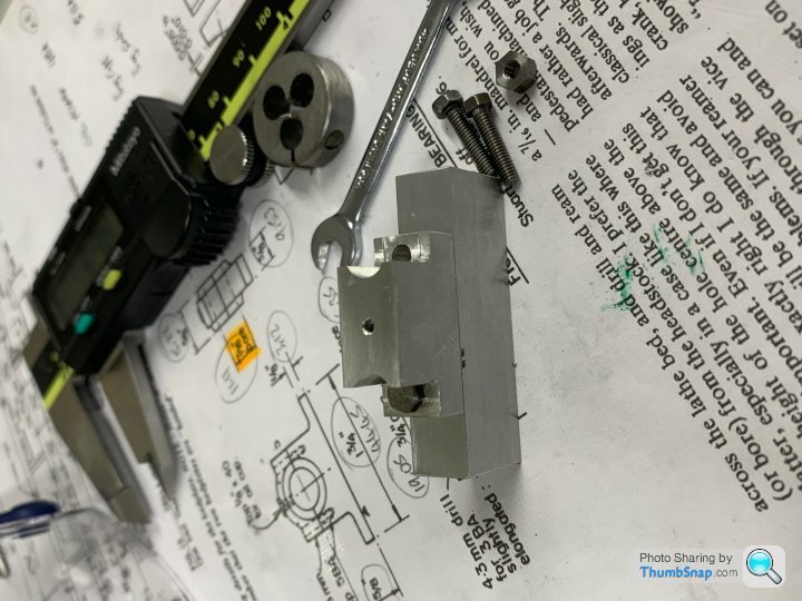
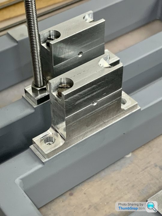
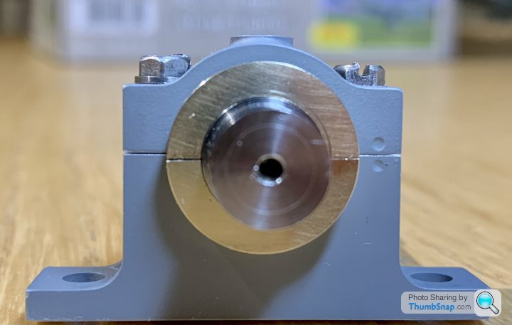
Everything went fine up to the point of bolting the halves together, when I found that there was on overlap of the cap bolts. I thought I'd machined it wrong, but basically if you make one bolt face right, the others (lowers) wont fit:
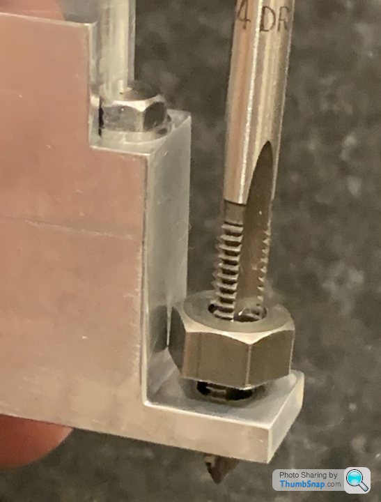
You can see the overhang here:
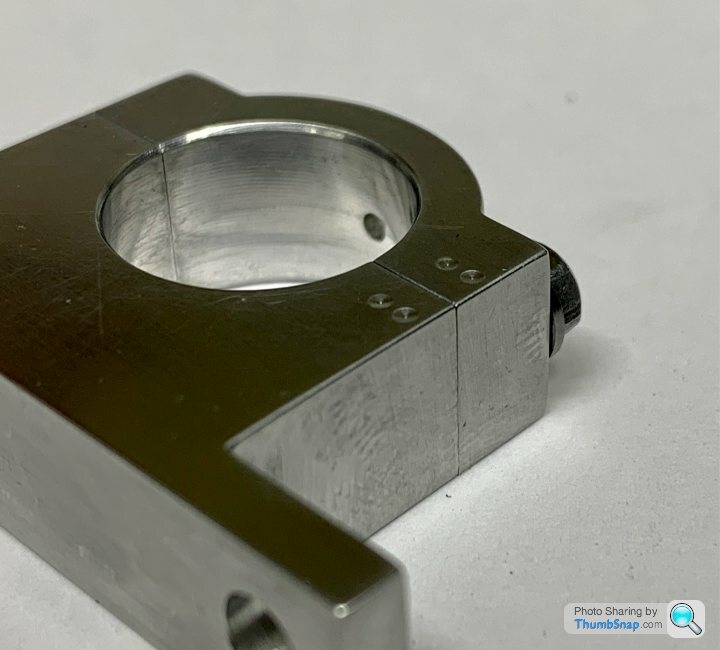
Turns out that there is a thing called "one size smaller" for BA fasteners, that means that, say, you can have a 5BA bolt, with a 6BA head:
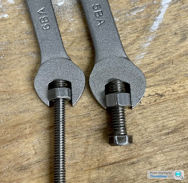
It also turned out that the lower nuts I'd got were oversized, and if I'd had the correct ones, everything would have - only just - fitted.
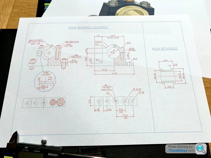
Anyway, I opted to scrap the half built ones, draw new ones out on CAD, and do my own drawings. I've added some radii featuures to add a bit of bulk, and tweaked the stud centres to give more room:
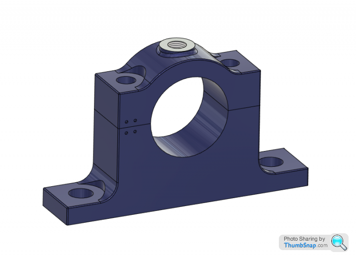
So I'll try again...at least only half finised one of them.
But it turns out there was a design change in the distant past, which means that they aren'r really suitable for this engine (too tall, plus the boss width is short on mine).
So, with some advice from the ME forum, I opted to make them from scratch out of aluminium, with separate split brass bearings. So I made a start:
Everything went fine up to the point of bolting the halves together, when I found that there was on overlap of the cap bolts. I thought I'd machined it wrong, but basically if you make one bolt face right, the others (lowers) wont fit:
You can see the overhang here:
Turns out that there is a thing called "one size smaller" for BA fasteners, that means that, say, you can have a 5BA bolt, with a 6BA head:
It also turned out that the lower nuts I'd got were oversized, and if I'd had the correct ones, everything would have - only just - fitted.
Anyway, I opted to scrap the half built ones, draw new ones out on CAD, and do my own drawings. I've added some radii featuures to add a bit of bulk, and tweaked the stud centres to give more room:
So I'll try again...at least only half finised one of them.
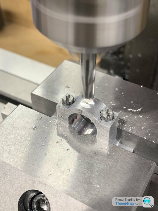
So, started again with the housings, a repeat of the previous process with a few minor tweaks for the additional radii:
I made a spigot to do the O/D, which worked well enough:
I also left the 1mm oil hole until after boring, because last time it caused a flaw when boring the hole:
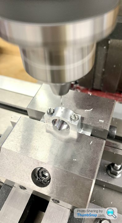
Milled a pocket for the oiler bosses:
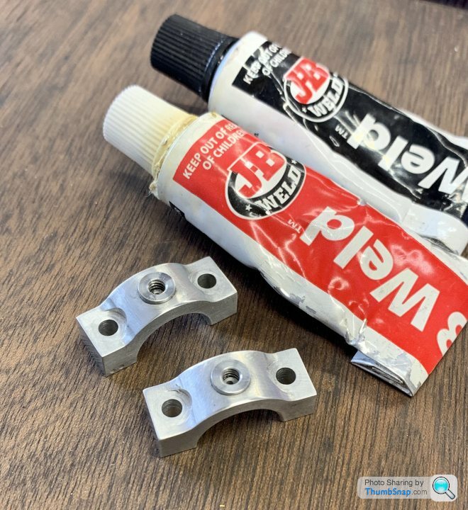
JB welded in place:
And a Milliput “rolling ball” fillet - far more satisfying than in CAD:
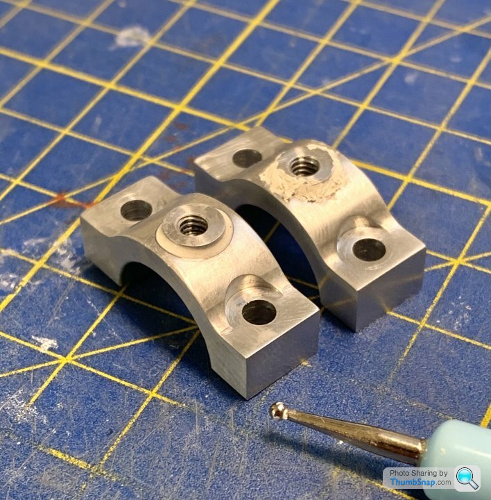
Currently awaiting primer:
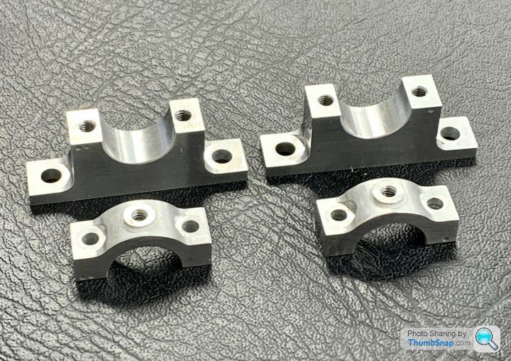
Next, the crankshaft I guess.
I made a spigot to do the O/D, which worked well enough:
I also left the 1mm oil hole until after boring, because last time it caused a flaw when boring the hole:
Milled a pocket for the oiler bosses:
JB welded in place:
And a Milliput “rolling ball” fillet - far more satisfying than in CAD:
Currently awaiting primer:
Next, the crankshaft I guess.
On to the split main bearings.
Hacksawed some square section brass bar into radius sized pieces:
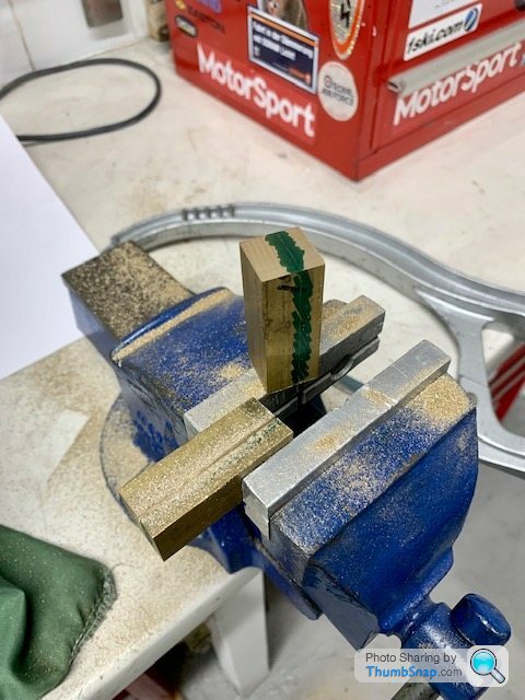
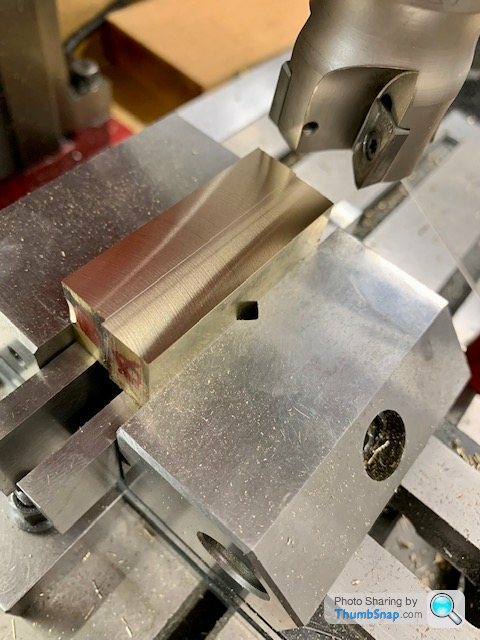
Milled them square:
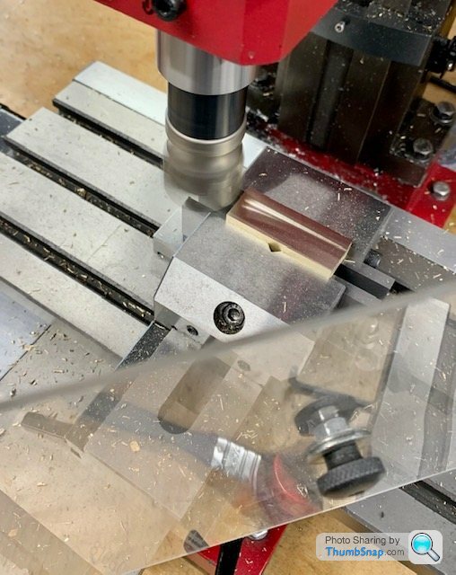
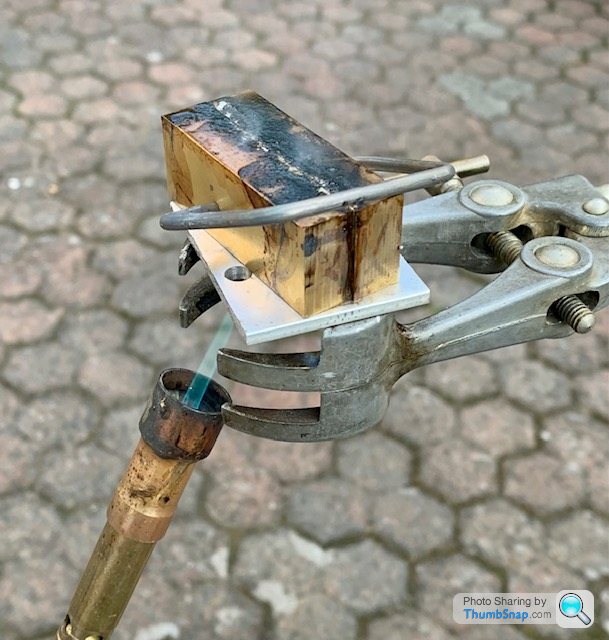
Tinned and sweated them together:
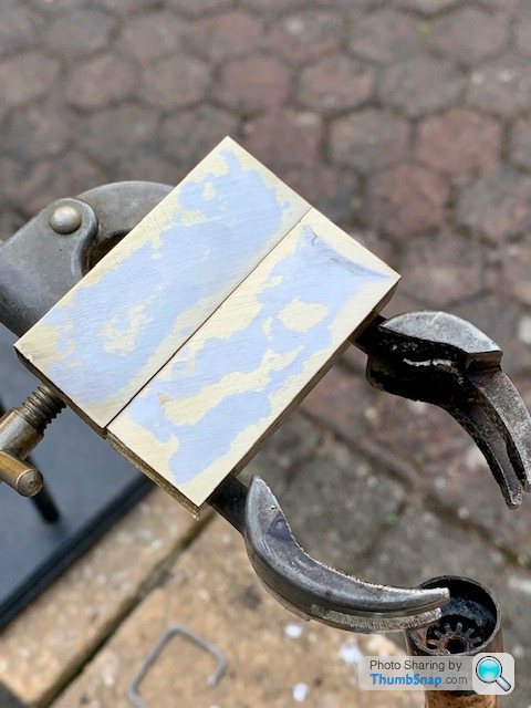
Them milled the assembly to clean-up the sides:
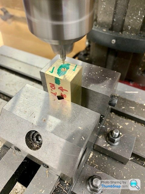
Centre drilled ready for fitting in the 4-jaw chuck ready for boring to crank journal size. Have to make the crankshaft first though:
Hacksawed some square section brass bar into radius sized pieces:
Milled them square:
Tinned and sweated them together:
Them milled the assembly to clean-up the sides:
Centre drilled ready for fitting in the 4-jaw chuck ready for boring to crank journal size. Have to make the crankshaft first though:
After much frustration and faffing with poor surface finish (turned out the material I was using was the wrong grade of steel- 080A15 vs. EN1A), finally made a start on the crankshaft:
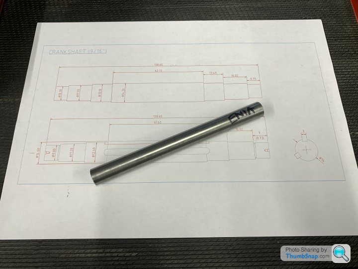
Opted to do it in two stages - roughing and finishing. Roughing done in the chuck:
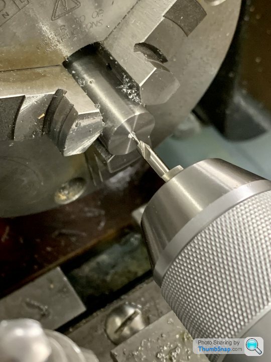
So far so good:
Finishing next, which will be done between centres (hence the centre drillings). Then I can use the shaft as a plug gauge for the split main bearings, cast crank webs, flywheel, eccentrics and governor pulley.
Opted to do it in two stages - roughing and finishing. Roughing done in the chuck:
So far so good:
Finishing next, which will be done between centres (hence the centre drillings). Then I can use the shaft as a plug gauge for the split main bearings, cast crank webs, flywheel, eccentrics and governor pulley.
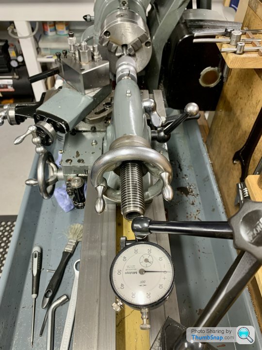
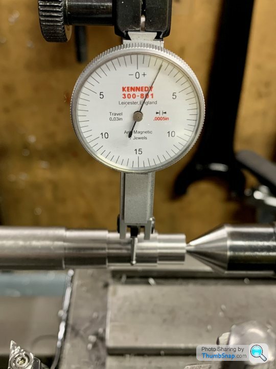
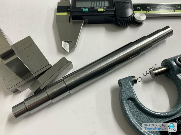
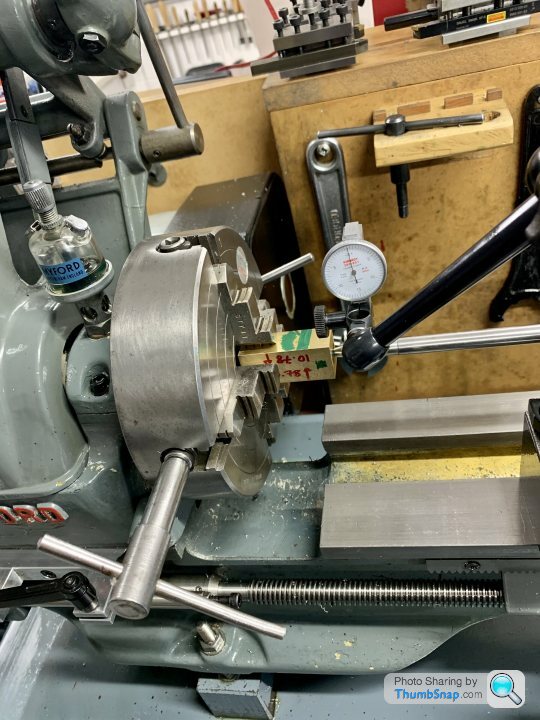
Spent ages adjusting the set-over of the tailstock, with it locked in place longitudinally, ready for turning the shaft. Managed to get it to zero on the calipers, turned out to be 0.0002” diameter difference with the micrometer. That’s over about 3.6”:
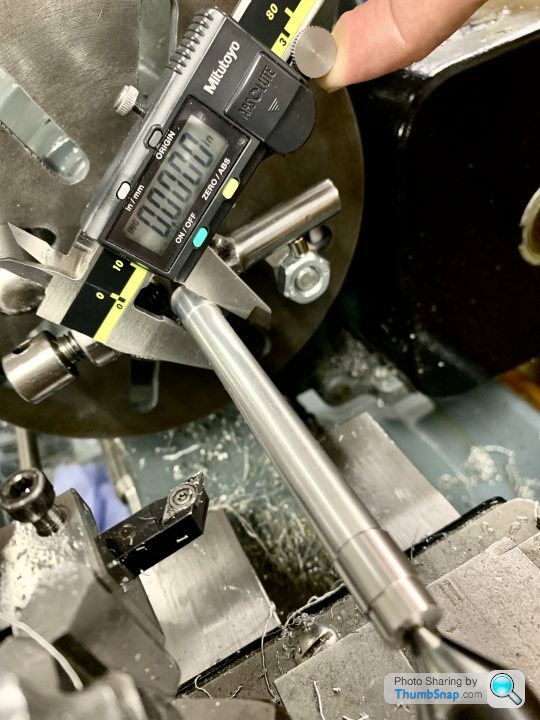
Hopefully that will be good enough because it got the stage of fractions of a turn tightening or loosening one adjuster shifted it from + to - size.
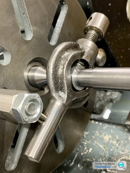
Also made an aluminium split sleeve to protect the steel shaft from the carrier:
Found a neodymium magnet to hold the carrier to the drive peg. I’m sure there’s a more traditional method, but this worked fine - held it together while turning, but allowed the work to be removed easily too:
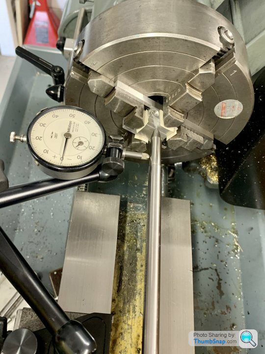
Runout on the turned parts is on average about 0.002”, easily lost in the excess material:
On to the axial error caused by the centre drillings, this was about 0.001”:
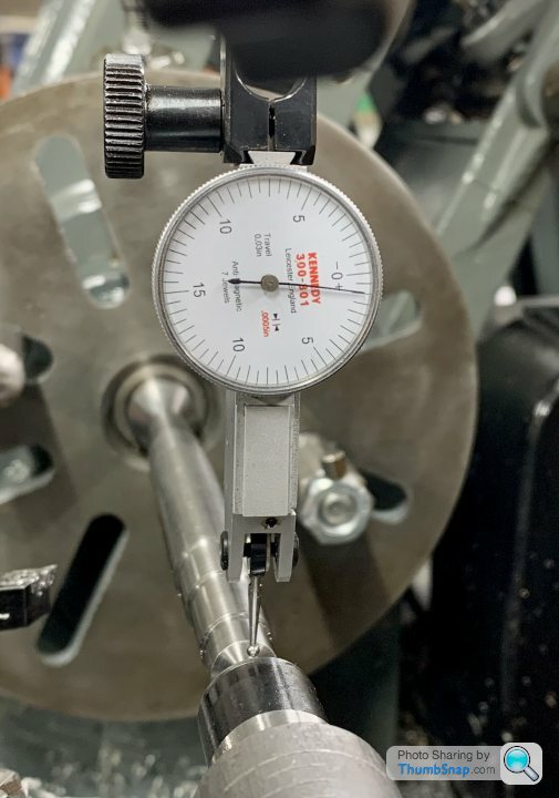
Might double-check the tailstock setting, then get in with finish turning the shaft next time.
Hopefully that will be good enough because it got the stage of fractions of a turn tightening or loosening one adjuster shifted it from + to - size.
Also made an aluminium split sleeve to protect the steel shaft from the carrier:
Found a neodymium magnet to hold the carrier to the drive peg. I’m sure there’s a more traditional method, but this worked fine - held it together while turning, but allowed the work to be removed easily too:
Runout on the turned parts is on average about 0.002”, easily lost in the excess material:
On to the axial error caused by the centre drillings, this was about 0.001”:
Might double-check the tailstock setting, then get in with finish turning the shaft next time.
Great progress on this one. I would suggest checking the movement whilst clamping the tailstock quill, as i have found on some lathes the quill lock tighness effects the reading. It tends to pull the quill from one side to the other. If the quill is locked tighter one time more than another the readings will differ, on a normal cut its not going to matter, but when your chasing small differences for a exacting finish cut it will.
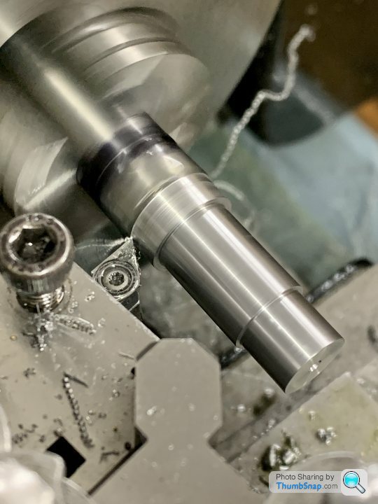
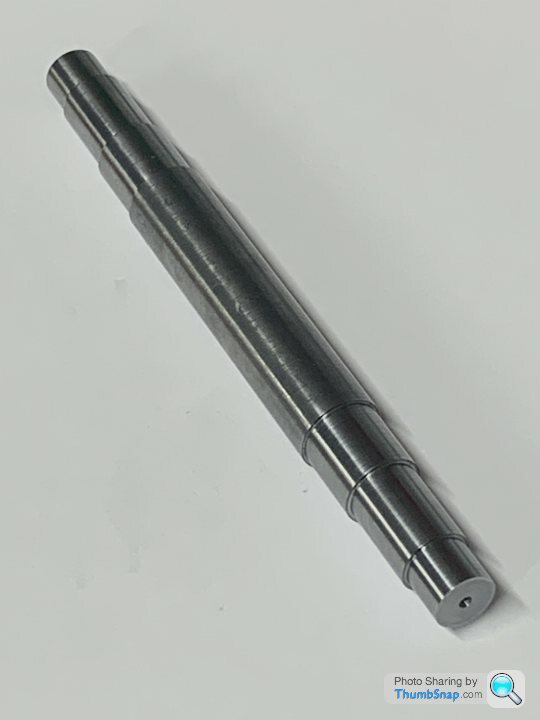
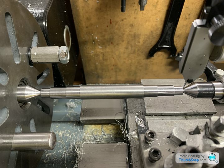
Turned the shaft between centres using slip gauges to get consistent lengths both sides. Also used the same final diameter tool setting and swapped ends to ensure identical diameters end-to-end:
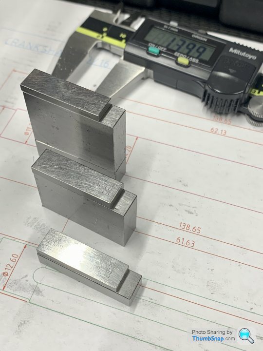
The result was 3 out of 3 diameters were identical to within the 0.0005” resolution of my digital calipers. I then switched to my micrometer 0.0001” resolution which showed 1 out of the 3 diameters to be identical, the remaining two were 0.0002” different.
This is after finishing with fine abrasive. I’ve left 0.25mm on the ends (as per instructions), so the centre drillings will end up a bit smaller.
alleggeria said:
What is the importance of having both sides of the shaft within such tight diameter tolerance relative to each other? You could also turn both sides and then adjust the bearings accordingly or am I missing something?
There is no reason other than if it’s easy to get it right, why not get it right?Folks on the ME forum seem mildly outraged by my method of using the same tool settings for each end of the work (and swapping the work around in sequence), despite it clearly giving a more consistent end result than finishing one end, then doing the other (at least for someone of my limited experience).
Say I finish one end, then measure, cut, measure, cut the other until I end up needing, say 0.0007” to get to the same as the other end. How am I supposed to take that cut accurately when my slide dial is graduated at 0.001”? In some cases the top slide can be angled to make one graduation effectively less (calculated using trig), but that then messes up the length stop distances. Far easier to do it as I have done (in my opinion).
They just say “that’s not how it should be done”, yet I don’t remember any technical reason being given as to why that’s the case…Maybe I misunderstood something or other, but the micrometer doesn’t lie, and the maximum error I’ve ended up end-to-end over the three pairs of diameters is 0.0002” (that’s about 5 microns). One of the pairs is bang on the same to the resolution of my micrometer, which is 0.0001” (about 2.5 microns).
Made a start on the split main bearings.
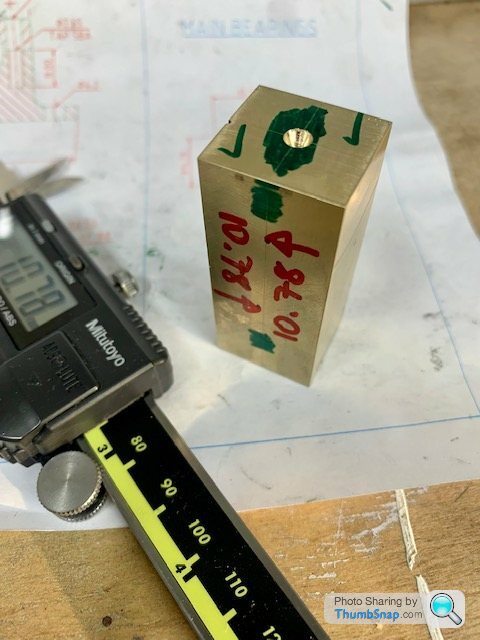
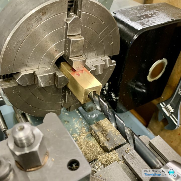
Centred the brass block:
Drilled to 10mm so I could a) get a boring bar in, and b) give clearance for the crank spigot so I could test fit the crank shaft all the way along it’s journal:
Faced off to form a thrust face:
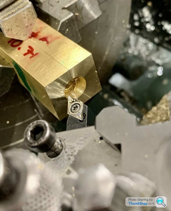
Then bored to a tight running fit on the crank:
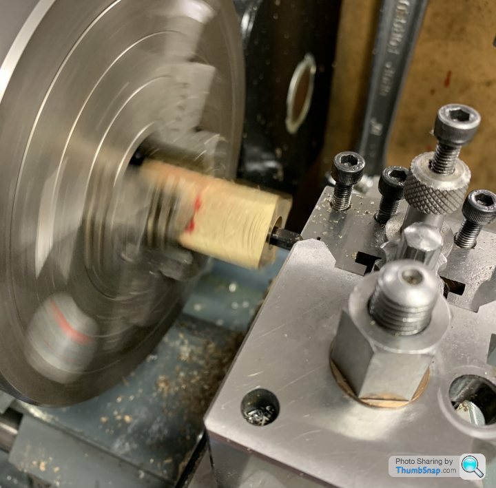
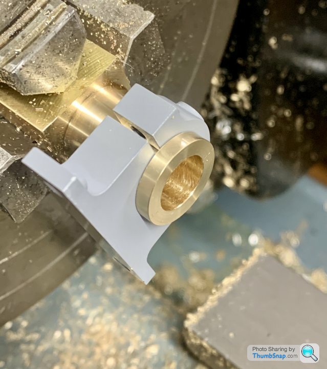
Then took intermittent cuts on the square to form the o/ds of the bearing side faces:
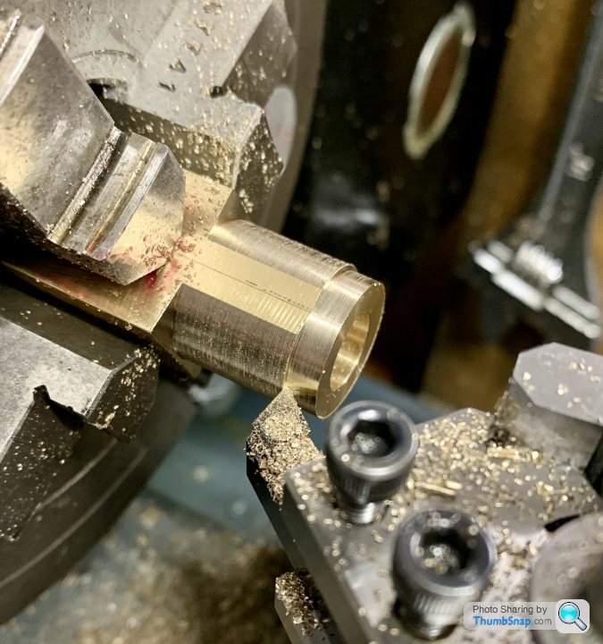
Unfortunately this partially broke the solder joint; when I test fitted the crank again, oil slowly bubbled out of the joint.
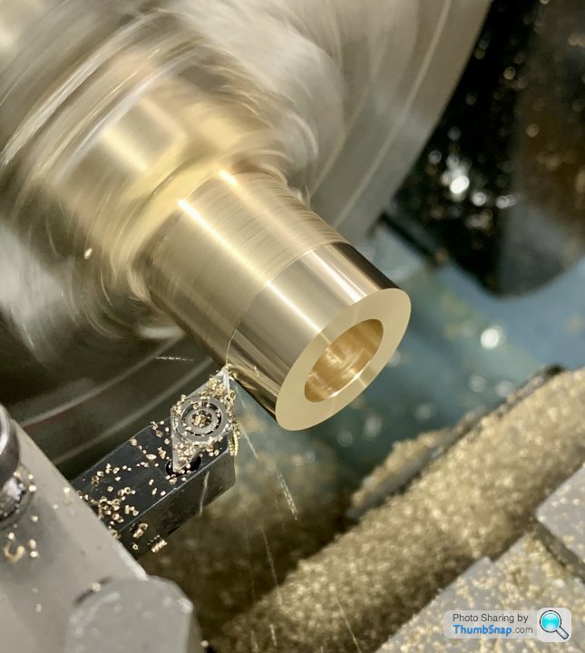
Anyway, thought I might as well carry on, so formed the bearing holder groove with a parting blade - deeper cuts at each end:
Test fitted until the halves just about closed:
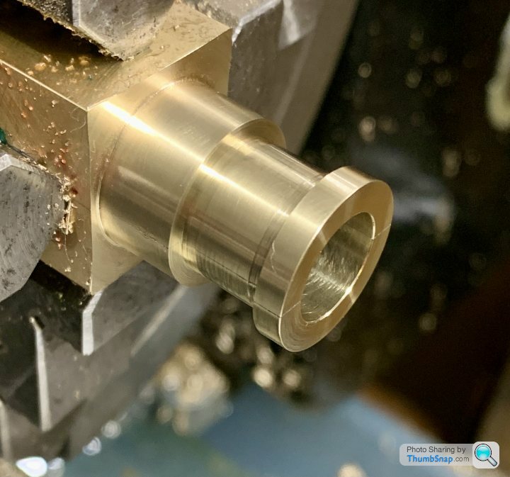
It fell apart after final parting, but after cleaning the faces it looked fine:
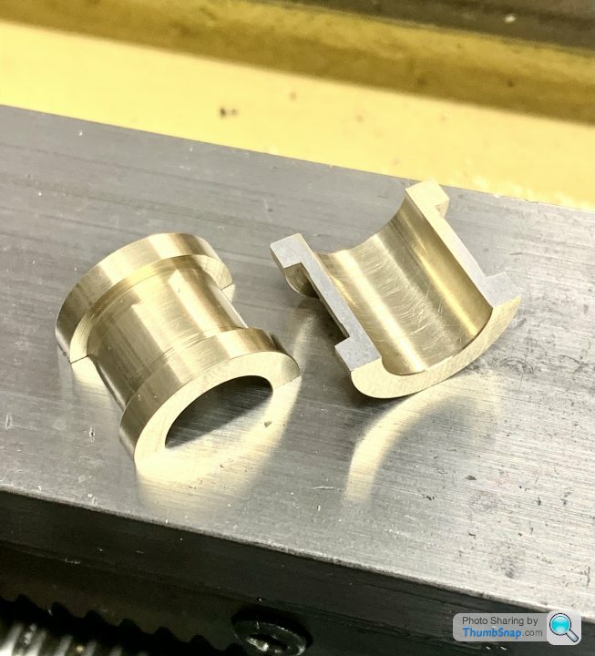
There is a bit of a gap left when the cap is screwed down to a good running fit. If fully tightened it gets a bit too tight for comfort. I expect once it’s been lapped in it’ll be spot-on:
The parted-off face needs thinning a bit, but I can do that with wet & dry on the surface plate.
I did make a mistake and over-bored a bit of the block at first, but hopefully I’ve got enough left to clamp in the chuck and make the other. Anyway, so far so good.
Centred the brass block:
Drilled to 10mm so I could a) get a boring bar in, and b) give clearance for the crank spigot so I could test fit the crank shaft all the way along it’s journal:
Faced off to form a thrust face:
Then bored to a tight running fit on the crank:
Then took intermittent cuts on the square to form the o/ds of the bearing side faces:
Unfortunately this partially broke the solder joint; when I test fitted the crank again, oil slowly bubbled out of the joint.
Anyway, thought I might as well carry on, so formed the bearing holder groove with a parting blade - deeper cuts at each end:
Test fitted until the halves just about closed:
It fell apart after final parting, but after cleaning the faces it looked fine:
There is a bit of a gap left when the cap is screwed down to a good running fit. If fully tightened it gets a bit too tight for comfort. I expect once it’s been lapped in it’ll be spot-on:
The parted-off face needs thinning a bit, but I can do that with wet & dry on the surface plate.
I did make a mistake and over-bored a bit of the block at first, but hopefully I’ve got enough left to clamp in the chuck and make the other. Anyway, so far so good.
Gassing Station | Scale Models | Top of Page | What's New | My Stuff